POLITECNICO DI MILANO
Scuola di Ingegneria Industriale e dell’Informazione
Corso di Laurea Magistrale in Ingegneria Energetica
Dipartimento di Energia
CO
2Capture in Integrated Steel Mills with the
Innovative Ca-Cu Capture Process
Anno Accademico 2014/2015
Relatore: Prof. Matteo Carmelo ROMANO
Co-Relatore: Isabel MARTINEZ
Tesi di Laurea di:
Matteo RAVELLI
Matricola 801262
III
ACKNOWLEDGMENTS
I would like to thank my thesis advisors Professor Matteo Carmelo Romano and Isabel Martinez for their guidance, support and counsel that led me during these months.
This work would not be the same without their knowledge and expert advice.
V
ABSTRACT
This thesis work focuses on Carbon Capture and Sequestration technologies in integrated
steel mills. Industrial sources account for a large portion of anthropogenic CO2 emissions
and the Steel industry is one of the main emitters in the industrial sector. Even more than in the Power Generation sector, the deployment of CCS technologies is going to be crucial for the reduction of carbon emissions in the Industrial sector, as for many industrial processes there isn’t any short-term alternative to fossil fuels. The first chapter of this work presents an overview of the present state of CCS in the Industry to outline the scenario in which this work is positioned. The second chapter offers an impression of the Steel industry and the steel production processes currently adopted in the world. In the third chapter the main CO2 capture technologies for integrated steel plants proposed by other authors and currently being researched around the world are presented to serve as a benchmark for the innovative technology presented in this work. In the fourth chapter is introduced the model of an integrated steel mill and its validation. The model allows to compute compositions and mass flow rates of the steel mill off-gases, which are the main source of carbon dioxide emissions in the steel plant. In the fifth chapter the application of the innovative carbon capture technology with Ca-Cu loop in an integrated steel mill is investigated. The integration of the Ca-Cu capture technology in a steam cycle power plant that uses steel mill off-gases as fuel has been modeled to assess its potential in terms of
CO2 emissions reduction and feasibility.
KEYWORDS: Steel; Blast Furnace; Carbon Capture and Sequestration; CO2; Greenhouse
VI
Questo elaborato di tesi si occupa di tecnologie per la cattura e il sequestro della CO2 in acciaierie integrate a ciclo integrale. Il settore industriale è responsabile per gran parte delle emissioni di CO2 antropogeniche e il settore siderurgico è uno dei principali emettitori del settore industriale. Ancora più che nel settore della generazione di potenza, l’utilizzo di tecnologie di cattura e sequestro dell’anidride carbonica sarà fondamentale per la riduzione delle emissioni di CO2 del settore industriale, in quanto per diversi processi non è disponibile alcuna alternativa ai combustibili fossili nel breve termine. Il primo capitolo di questo elaborato presenta una panoramica sullo state attuale delle tecnologie CCS nel settore industriale al fine di delineare lo scenario in cui questo lavoro si colloca. Il secondo capitolo offre un’introduzione al settore siderurgico e una descrizione dei processi di produzione dell’acciaio comunemente in uso al giorno d’oggi. Nel terzo capitolo vengono presentati i processi di cattura della CO2 in acciaierie integrate presentati da altri autori o correntemente oggetto di ricerca, per servire da riferimento per la tecnologia di cattura innovativa proposta in questo elaborato. Nel quarto capitolo viene introdotto un modello di una acciaieria integrata e la sua validazione. Il modello consente di calcolare le composizioni e le portate dei gas di processo prodotti nell’acciaieria, che sono la principale fonte di emissioni di carbonio dell’impianto. Nel quinto capitolo viene investigata
l’applicazione del sistema di cattura della CO2 con processo Ca-Cu ad una acciaieria
integrata. E’ stata modellata l’integrazione del processo di cattura Ca-Cu in un impianto di produzione di potenza a ciclo a vapore che utilizza i gas d’acciaieria come combustibile
per valutarne il potenziale in termini di riduzioni di emissioni di CO2 e di fattibilità.
PAROLE CHIAVE: Acciaio; Altoforno; Cattura e Sequestro del Carbonio; CO2; Emissioni di Gas Effetto Serra.
VIII
1 CCS IN THE INDUSTRY ... 11
1.1 CCS IN INDUSTRIAL APPLICATIONS ... 11
1.2 CAPTURE TECHNOLOGIES FOR INDUSTRIAL APPLICATIONS ... 14
1.3 STATUS OF CCS... 15
1.4 CO2STORAGE ... 16
2 THE IRON AND STEEL INDUSTRY ... 17
2.1 WORLD STEEL PRODUCTION AND PROJECTED EMISSIONS ... 17
2.2 IRON AND STEEL PRODUCTION PROCESSES ... 19
2.3 INTEGRATED STEEL MILL WITH BLAST FURNACE ... 20
2.3.1 Sinter Plant... 21
2.3.2 Coke Oven ... 22
2.3.3 Blast Furnace ... 22
2.3.4 Basic Oxygen Furnace ... 24
2.4 ELECTRIC ARC FURNACE ... 25
3 CO2 CAPTURE TECHNOLOGIES IN THE STEEL SECTOR ... 27
3.1 OVERVIEW ... 27
3.2 PRE AND POST-COMBUSTION CO2 CAPTURE TECHNOLOGIES FOR INTEGRATED STEEL MILLS ... 29
3.2.1 Post-combustion capture with MEA ... 29
3.2.2 Pre-combustion capture with MDEA ... 31
3.2.3 Pre-combustion capture with SEWGS ... 31
3.3 ULCOS ... 34
3.3.1 Top Gas Recycling Blast Furnace ... 35
3.3.2 HIsarna Smelter technology ... 36
3.3.3 ULCORED ... 37
3.3.4 Alkaline Electrolysis ... 38
4 THE INTEGRATED STEEL MILL MODEL ... 39
4.1 THE COKE OVEN PLANT MODEL ... 39
4.1.1 Coke Oven ... 40
4.1.2 Coke Oven Combustion Chamber ... 44
4.2 THE BLAST FURNACE MODEL ... 46
IX
4.2.2 Blast Furnace Modeling ... 51
4.2.3 Hot stoves ... 55
4.2.4 Blast Furnace Model Validation ... 55
4.3 THE BASIC OXYGEN FURNACE MODEL... 57
4.4 COMPLETE PLANT MODEL ... 60
4.5 POWER PLANT ... 64
5 THE CA-CU CARBON CAPTURE TECHNOLOGY ... 67
5.1 THE CONCEPT ... 67
5.2 THE SEWGS REACTOR ... 70
5.3 THE FUEL REACTOR... 72
5.4 THE AIR REACTOR ... 73
5.5 POWER PLANT WITH CA-CU CAPTURE PROCESS ... 75
5.6 CO2 EMISSIONS REDUCTION ACHIEVED ... 82
1
CCS IN THE INDUSTRY
This chapter offers an overview of Carbon Capture and Sequestration in the industrial sector, to outline the global contest in which this thesis work is positioned.
1.1 CCS in Industrial Applications
The awareness of Climate Change has grown around the world and to need to act and modify energy and environmental policies is becoming a priority. To achieve the ambitious goal that has been set by the IEA, Energy Efficiency and Renewable Energies will have to play a major role but Carbon Capture and Sequestration (CCS) technologies will have to play a crucial role in order to reach the emissions reduction target that has been set for 2050. The IEA stated that to limit the global warming to a maximum of 2°C,
CO2 emissions must be cut by 50% of their 2005 level and CCS in Power Generation and
Industrial applications contribution to this achievement is expected to be of 19% [1]. Although CCS has been mainly seen as a “Coal-Technology”, due to its high emission reduction potential in coal fired power plants applications, the potential of CCS in industrial applications is great and must not be underestimated. Especially because CCS is the often the only available option to reduce Carbon emissions in many industrial sectors
12
(except energy-efficiency measures), where a switch to an alternative to fossil fuels is not conceivable. CO2 emissions of the industrial sector are estimated to be 20% of the global anthropogenic emissions by large stationary sources, with the Iron and Steel Industry estimated around 5% [9]. The increasing cost of energy in the last 50 years has driven the Steel Industry to pursue energy efficiency to reduce the production cost and there isn’t much room for more improvement, therefore CCS represents the only way to achieve deep CO2 emissions reductions in the Steel Industry.
CCS technologies have the potential to reduce CO2 emissions by up to 6.0 Bt annually by 2050 in industrial applications [5] (13% of the amount required to meet the 2050 target).
Figure 1 Contribution of technologies and sectors to global cumulative CO2 reductions [5]
To do so 20% to 40% of the existing industrial facilities would need to equipped with CCS, an ambitious target that needs extensive planning and support by the governments, that will have to drive the industry with funding and incentives, in the direction of change and innovation. Indeed in the IEA projection for 2°C temperature increase scenario (2DS) half of the CO2 captured by CCS would have to come from the industry sectors, where there aren’t feasible alternatives to CCS for achieving significant emissions reductions. In a Baseline scenario where no new policies (other than the ones already in place) are applied to stimulate the deployment of emissions reduction technologies, IEA projects the
global CO2 emissions of the industrial sector, estimated to be 7.4 Gt in 2008, to grow by
83% by 2050, when they will represent 18% of the total global energy-related CO2 emissions [1].
Chapter 1
13
Figure 2 Industrial CO2 emissions projections [1]
To achieve a significant emissions cut the deployment of CCS technologies in the industrial sector is essential and the application of new policies by the governments is necessary. The Iron a Steel sector contributes with a very significant share, and CCS is the only viable solution to effectively reduce carbon dioxide emissions in the Steel sector. Some CCS technologies, such as capture from high purity sources and CO2 transportation in pipelines, are a consolidated reality and have been used by the industry for several years especially for EOR (Enhanced Oil Recovery) practice (it must be noted EOR to be considered CO2 storage needs to be accompanied by monitoring and verification). Carbon Dioxide has been successfully injected in exhaust oil reservoirs and stored for years, to improve oil production. Industrial processes that separate CO2 as part of the process are
known as high-purity CO2 sources, and applying CCS technologies to these high
concentration flows presents few technological challenges and five demonstrating CCS projects are already in operation today. CCS demonstration projects are on their way in many industrial fields and new technologies are being researched by publicly and privately financed research groups.
14
1.2 Capture Technologies for Industrial Applications
Several industrial processes do not remove CO2 as part of the process itself and therefore they require additional separation technologies in order to concentrate dilute streams of carbon dioxide to a level that enables economically feasible transportation and storage. An example are iron and steel furnaces, cement kilns and refineries, where the application of CCS highly depends on cost and reliability. Capture technologies often comprise partial oxidation or full combustion of hydrocarbons, together with chemical/physical absorption, adsorption ,cryogenic separation and liquefaction. They can be divided in three categories:
CO2 removal from diluted streams (post-combustion capture): CO2 is
selectively removed from the low-pressure flue gases using chemical or physical solvents, which are then regenerated to obtain a concentrated CO2 stream.
o Chemical solvents create a chemical bond with the CO2 and separate it from a gaseous stream. The CO2-rich solvent needs to be stripped with steam to
separate the CO2 and regenerate the solvent. The concentrated CO2 stream
can then be compressed and stored. Typically MEA or other amines are used as chemical solvents, which are very effective at capturing in low CO2 partial pressure flows. Chemical solvents are highly effective at removing
CO2 from low concentration flows, however the energy demand for the
solvent regeneration process is very high.
o Physical solvents are liquids that can remove carbon dioxide by physical absorption of the CO2 into the liquid. The physical solvent is regenerated by pressure reduction, which require less energy than chemical solvents, but physical solvents need a higher CO2 partial pressure to operate and there could be some other gaseous component left in the final CO2-rich stream due to co-absorption effects.
o Solid sorbents, such as zeolites, calcium oxide, activated carbon and metal
organic frameworks, can adsorb CO2 on their surface and then release it
Chapter 1
15
and PSA (pressure swing adsorption) can achieve significant energy savings over solvents in certain applications.
CO2 removal from oxy-fired streams (oxy-combustion): streams with high CO2 concentration (absence of nitrogen) are obtained feeding pure oxygen instead of air to the process. The streams can be transported and stored after particulate and contaminant removal (in some cases flue gas desulphurization and water removal may be necessary). Oxy-firing can be more efficient than solvents but the majority of industrial processes are not designed to operate in oxygen-rich environments and would require process adjustments to adopt this capture technology.
Pre-process CO2 removal (pre-combustion): fossil fuels (or biomass) are gasified
with partial oxidation to produce a hydrogen-rich syngas, which is then subjected to water-gas shift reaction (CO is converted to CO2) to improve hydrogen conversion. The syngas can be used for carbon-free power and heat generation to satisfy the plant request or as input in further industrial processes. The CO2 is available at higher concentration, making easier the final separation, using solvents/sorbents or membrane separation, before transport and storage.
1.3 Status of CCS
The IEA reports that in 2015 in the world there were 15 large-scale facilities capturing 27 Mt of CO2 per year [5]. Especially the Sleipner natural gas production plant in Norway, has been successfully capturing and storing 1 Mt of CO2 per year for almost 20 years, and in the United States CO2 has been used to EOR for decades using a pipeline network of 6,600 km.
While in the power generation sector CCS is already up and running, with the operating coal-fired power plant with CCS which started operations in 2014 in Canada, and 2 more projects expected to come in operation in 2016 in the United States, in the industrial sector CCS is still an R&D phase, with the first pilot plants being built to understand which capture technology works best in each field. However the success of CCS in the power generation and its 20 year long history in the gas processing and EOR, must be seen by the
16
industry as demonstration of the viability of technology and stimulate the players to invest in the development and deployment of CCS in the industrial sector, as it is the only feasible solution to achieve the emissions reduction goals that have been set by the IEA.
1.4 CO
2Storage
Once a high purity CO2 stream is isolated a suitable solution must be found to permanently prevent it from being released to the atmosphere. Geological storage of gaseous CO2 in appropriate geological formations, such as saline and exhausted oil and gas fields, has emerged as the most ready and easily deployable solution. Carbon dioxide is directly injected into the storage site, where physical and geochemical trapping mechanisms are in
action and ensure that the CO2 will safely be stored underground without ever being
released to the atmosphere again. An example is the Enhanced Oil Recovery (EOR) practice, in which CO2 has been injected into declining oil reservoirs to increase the productivity of the oil field for years and is a well-established technology in the Oil & Gas industry. Ocean storage had been explored as an option in the past but it has been discarded because of the potential impact on the acidity level of the oceans and is no longer investigated. Mineral storage is another potential solution under investigation. The process would exploit the natural reaction of CO2 with available metal oxides to produce stable carbonates, the reaction naturally happens in nature but it requires long periods of time and would the use of a catalyst or a high pressure/temperature environment would be necessary for CCS applications.
2
THE IRON AND STEEL INDUSTRY
This chapter presents an overview of the Iron and Steel Industry, to outline the relevance of the sector and its related emissions. The main steel production routes are described, with a greater emphasis on the Blast Furnace/Basic Oxygen Furnace route which is the main focus of this thesis work.
2.1 World Steel Production and projected emissions
Steel is one of the most important commodities traded on a global scale, it finds application in several industries and plays a crucial role in the development and industrialization of a country. The world steel production has increased considerably since the year 2000 and exceeded 1000 million tonnes for the first time in 2004. In 2015 world crude steel production reached 1622.8 million tonnes [10], a growth that is mainly attributable to China, whose share of production is 49.5%, and other developing countries.
18
Figure 3 Annual world steel production [10]
The Iron and Steel industry is a very energy intensive one, and the use of coal as primary fuel for iron and steel production in the Blast furnace/Oxy-furnace route makes it the highest CO2 emitter of any industry. According the IEA, the iron and steel industry accounts for the largest share of CO2 emission from the global manufacturing sector, approximately 27% [11]. The world steel production is expected to grow up to 2200 Mt a year in 2050, driving a significant increase in energy use and CO2 emissions, so great that the adoption of the best available technologies for energy-efficiency wouldn’t be enough to meet the emissions reduction goals that have been set for the future (2030 or 2050), and therefore the development and deployment of CCS technologies or alternative routes for iron making is crucial. The deployment and adoption of these technologies will be essential, and will be driven by economic viability which needs to achieved with the help of adequate governmental policies.
Chapter 2
19
2.2 Iron and Steel Production Processes
Worldwide, steel is mainly produced by two major routes: the Integrated Route based on Blast Furnace and Basic Oxygen Furnace as primary route that produces steel from virgin iron and the Electric Arc Furnace (EAF) route, which is a recycling route that produces steel from scrap (recycled steel), using mainly electric power as energy input. These two represent roughly 65% and 30% respectively of the world steel production [11], but they aren’t the only processes in use in the world today and many more are currently being studied or tested. EAF mainly uses electric power as input, and its CO2 emissions are mainly related to power generation. Although the relative share of EAF is expected to grow, due to an increase of recycled materials, to sustain the industrial growth of developing countries ironmaking routes will still be playing the biggest part in steel making, at least in the medium-long term.
Figure 5 Crude steel production methods [7]
The integrated steelmaking process using BF will continue to play a dominant role in the industry for a long time [12], for that reason it is important to develop capture technologies that would be easily and economically applicable as retrofit to existing plants to speed up and facilitate the CCS deployment in the steel sector.
20
The smelting reduction process and the direct reduction iron (DRI) are emerging as alternatives to the BF/BOF route but their contribution to the global steel production is still very modest. The smelting reduction process combines the gasification of non-coking coal with the reduction of iron ore in a liquid bath, allowing to avoid the use of coke whose production is an energy intensive process with significant associated CO2 emissions. The smelting reduction furnace is oxy-fired, resulting in a higher CO2 concentration in the flue gas which facilitates CO2 capture [12].
DRI process accomplishes the reduction of iron ore is a solid form using natural gas as reducing agent. They are typically small scale plants ( below 1 Mt/yr) [12] and are diffused in countries where the cost of natural gas is low. In absence of melting of a slag phase, DRI requires a further separation process in an electric arc furnace.
2.3 Integrated Steel Mill with Blast Furnace
The BF/BOF route is by far the most widespread ironmaking technology. It is an integrated plant where several units perform different interconnected processes, exchanging material flows and energy with each other. In the Blast Furnace iron is reduced and melted to created pig iron (also called hot metal). The hot metal is then sent to the Basic Oxygen Furnace where a further reduction is performed to reduce the carbon content of the metal and remove impurities to create liquid steel. Another important unit is the coke oven, where coke, which is the most important feed to the blast furnace both as fuel and as reducing agent, is produced. A power plant, which uses the residual process gases as fuel, is always present to produce electric power and steam used by the processes. Iron ore is prepared to be fed to the blast furnace in a sinter plant. The biggest CO2 emission source of the Steel Mill is the Blast Furnace, which accounts for 69% of all the Steel Mill emissions to the atmosphere [2], in figure 7 the main emission points of the a typical Integrated Steel Mill are shown.
Chapter 2
21
Figure 6 CO2 emissions (kg/t of hot rolled coil) from a typical steel mill [2]
2.3.1 Sinter Plant
The Sinter process is meant to improve the permeability and reducibility of the burden before feeding it to the blast furnace to improve its performance, as well as to agglomerate a mixture of iron ores, additives and iron-bearing materials. Coke breeze is added to the mixture to enable ignition of the sintering process.
The burden is charged on a moving grate where a series of burners ignites heats up the mixture and ignites the coke combustion, which allows the sintering process to take place. Combustion air is fed through “Wind Boxes” throughout the sinter reactor, and when the coke combustion is complete the same air starts to cool down the sintered material, which is then collected and prepared to be sent to the blast furnace. The burners are typically fed with a mixture of Blast Furnace Gas and Coke Oven Gas. The flue gas resulting from the combustion of these fuels and the coke present in the charge are typically between 1500 and 2500 Nm3 per tonne of sinter produced [7] and contain a series of impurities and
pollutant (heavy metals, dust, NOx, SOx) which need to be removed before sending to
chimney. Of course the flue gas has carbon dioxide content, which makes the sinter plant
22
2.3.2 Coke Oven
In the coke oven the pyrolysis of coal is performed to obtain coal. Coking coal is heated up to 1000-1100 °C for 14-24 hours in an oxygen-free environment, where it modifies its composition turning into coke (solid) and releasing a gas that is collected at the top of the reactor (Coke Oven Gas). Coke functions both as support material, heat supply and reducing agent in the blast furnace and it can’t be wholly replaced by any other material. Coke ovens are made of several chambers with refractory walls, coal is charged in every other chamber while in the other ones a flow of hot gas heats up the walls that give back the heat in next room where the pyrolysis reaction takes place. During the whole process duration the ovens are kept closed and slightly in pressure to avoid the air infiltration. The combustion chambers require fuel to supply heat to the coking process, the COG itself or a mixture of COG and other process gases is used. The production of COG is higher than the internal consumption in the coke oven and COG is used as fuel in other units of the plant.
Thus the coke oven is another main CO2 emission point
2.3.3 Blast Furnace
The Blast Furnace is a very big thermo-chemical reactor, it is continuously fed with the sintered charge, coke and some additives. At the bottom of the furnace a hot air blast is blown to have a partial combustion of the coke, to generate the heat necessary to melt the charge, and at the same time create a reducing gas stream that flows countercurrent to the solid stream, from the bottom to the top of the furnace. The gas that is created is CO-rich gas, that reacts with the iron oxides generating CO2. Coke is not just the fuel that supplies heat to the furnace but it plays the most important role in the blast furnace producing the reducing gas that turns iron oxides into metal iron, it is a key structural element because it sustains the weight of the charged material but at the same time it is a porous bed through which the molten metal and the reducing gas can flow. Moreover it supplies the carbon that, once melted, goes in solution with metal iron to form pig iron.
Chapter 2
23
Other fuels (typically pulverized coal or natural gas) can be fed to the furnace, to reduce the amount of coke consumed, but coke can never be fully replaced because of its crucial structural role.
Figure 7 General view of two blast furnaces [7]
The charge slowly move downwards inside the furnace while its temperature grows, iron oxides progressively reduce while oxidizing coke and the carbon monoxide of the reducing gas. As it gets closer to the bottom the metal reaches the melting temperature and the hot metal is collected at the bottom together with the slag, which is then separated by density difference. The reducing is gas collected at the top the furnace and is called Blast Furnace Gas. BFG still has a modest LHV, due to the presence of residual CO and hydrogen, and is used throughout the plant as fuel. The high mass flow rate and the high carbon content make it the main CO2 emission source of the plant.
To lower the furnace energy input the air is pre-heated before blowing it in the reactor. The pre-heating of the air blast is done in chambers with refractory walls that are called Hot Stoves. A stream of hot flue gas (900-1350°C) and the air stream alternatively flow through the chambers, exchanging heat with the refractory walls. To heat up the walls to 1100-1500 °C a mixture of BFG and COG is burned in the hot stoves, causing CO2 emissions at the chimney.
24
Figure 8 Hot Stove cross section
2.3.4 Basic Oxygen Furnace
In the BOF the hot metal is finally turned into steel. After leaving the blast furnace the hot metal is treated to remove Sulphur and then it is sent to the BOF. The operation is discontinuous: the hot metal is periodically loaded, undergoes the process and is unloaded as liquid steel.
A high purity oxygen flow is blown in the reactor to oxidize impurities and to lower the
carbon percentage to a steel grade oxidizing the carbon of the hot metal to CO and CO2.
The impurities are separated into a slag and the resulting process gas (BOFG), which has a residual calorific value, can be used as fuel in other units of the steel plant, and will be a source of CO2 emissions.
The metal is fed to BOF already in liquid phase and the oxidation reactions are exothermic and release additional heat, hence the BOF doesn’t require any energy input. Conversely the temperature of the bath must be controlled to avoid reaching too high temperature that can lead to structural failure of the furnace, therefore the extra-heat available is exploited by melting some recycled steel scrap, enlarging the steel production.
Chapter 2
25
Figure 9 Basic Oxygen Furnace [13]
2.4 Electric Arc Furnace
The EAF routes melts recycled materials, such as steel scrap or slag, using high-energy electric power. The specific energy consumption is 30-40% lower than the Integrated BF/BOF route but the cost of electric power is higher, and it only allows to produce steel using recycled materials and thus can only supply an amount of steel limited to the recycling rate, clearly not enough to meet the constantly growing demand of steel. The EAF is a very flexible process, the plant can be turned easily on and off and is able to freely follow the demand/supply of steel scrap. The EAF is the only major unit of the entire route, indeed the scrap is loaded in the furnace as it is, without any pre-treatment, and in the reactor is directly produced liquid iron, ready for the final refinement treatments. The EAF is a bath-type furnace, in which is heat is mainly supplied by very high temperature electrodes. The walls are equipped with supplementary gas-fired burners to supply extra heat and maintain the temperature of bath as homogenous as possible. High-purity oxygen is blown to reduce the impurities and obtain pig iron, the reduction reaction release heat that contributes to the melting process and a CO-and-CO2-rich exhaust gas is produced. The exhaust gas is the only in-site CO2 emission of the EAF plant, which is very
26
moderate if compared to the BF/BOF route, but the main emission source of the EAF is, indirectly, the electric power used to power the furnace. The CO2 emitted to produce the power consumed in the EAF is considerably larger than the on-site emission related to the reduction of the impurities, making a potential CO2 capture of the latter inconvenient.
3
CO
2CAPTURE TECHNOLOGIES IN THE
STEEL SECTOR
This chapter presents an overview of the current status of CCS technologies in the Iron and Steel Industry, presenting the best available technologies and the most promising development for the future. The aim is to describe the present scenario in order to assess and relate the performance of the innovative Ca-Cu technology that will be presented in Chapter 5.
3.1 Overview
The high cost of fuels and electricity in the last decades has driven to Steel Industry to pursue energy efficiency, and it estimated that a state-of-the-art Blast Furnace operates 5% away from thermodynamics and looking at the Mill as a whole potential energy savings could roughly be 10% only [2]. The average Carbon Intensity of a Steel Production Plant is estimated to be 1.7 tons of CO2 per tonne of crude steel casted [20] , therefore to obtain the significant CO2 reductions that are required by the latest policies, simply chasing efficiency and energy savings would not be enough and the deployment of CCS
28
technologies will be necessary. Keeping a high level of recycling will be important and would bring substantial indirect emissions reduction, as the biggest part of the emissions from the production of Steel from recycled scrap in EAF plants comes from the electric power, the industry could benefit from the expected reduction of the carbon intensity of the power sector. However the ore-based route will continue to play a major role in steel production for at least another century, especially driven by the “Steel Thirst” of developing countries. Solutions to reduce carbon dioxide emissions from the ore-based routes are being researched by many R&D programs around the world, like the ULCOS
(Ultra Low CO2 Steelmaking) has been running in the EU since 2004 and has come up
with different options, some of which are already in a fairly advance phase of developed being test in small-scale pilot plants.
Steel production is mainly based on coal or on electric arc furnaces, with a minority of production coming natural gas based technologies or a combination of carbon and hydrogen. In the present scenery three routes have emerged as viable solutions:
Decarbonizing: a shift away from coal, replacing carbon as main reducing agent
and fuel with electricity (electrolysis of iron ore) and hydrogen (hydrogen reduction).
Adopting CCS technologies.
Using Biomass as a sustainable source of Carbon based reducing agents.
The possibility of switching to Hydrogen as reducing agent will heavily depend of the availability of Hydrogen at reasonable cost and with low related CO2 emissions, and the use of charcoal in a large-scale would require the deployment of logistics and infrastructure to connect the growing countries to the Steel Mills.
The long development time and risk associated with the adoption of new breakthrough technologies, together with the large R&D budgets and capital costs associated with the construction a brand new greenfield plant, show how the future policies and the cost of CO2 will likely be the main driver for the future of the steel industry and how technologies suitable for retrofitting in existing plants, such as the TGR or the innovative Ca-Cu capture technology that will be presented in this work, will play a major role in reducing the emission of the steel sector, especially in the short and medium term. Other programs all
Chapter 3
29
over the world are working on the same pathway of the ULCOS program in Europe, with the same goal of finding new breakthrough technologies to reduce the carbon footprint of the steel industry, but they are less advanced and their progress and results have not widely been made available yet.
3.2 Pre and post-combustion CO
2capture technologies for Integrated
Steel Mills
Developing new Steel-making processes with (ideally) zero CO2 emissions is a long term
goal for the Carbon-free society of the future, however in the short term, the key to obtain a widespread deployment of CCS in the Steel Industry is finding economically feasible ways to implement CO2 capture technologies in existing plants. Pre and post-combustion CCS technologies are mature technologies, that have benefitted of the heavy investments made in the Power Generation Sector, and represent a ready-to-go option for retrofitting of existing plants. In Integrated Steel plants all the units are responsible for a portion of emissions, which can always be attributed to the combustion of the blended process gases. The power plant is the main emission point accounting for 40-70% of total emissions, followed by the hot stoves (15-30%), the coke oven combustion chambers (15-20%), the sinter plant (5-20%) and the lime kiln (2-5%) [20]. The power plant uses the biggest portion of the carbon-rich process gases and is the main CO2 emission point of the Steel Mill, therefore applying CCS to the power plant is an easy and effective option to halve the CO2 emissions of the whole plant without modifying the steel production process.
The following analysis mainly refer to Integrated Steel Mills with a gas-fired Combined Cycle as power plant, as this is the standard for most of new plants built with BAT.
3.2.1 Post-combustion capture with MEA
The amine post-combustion process is a chemical absorption CO2 capture process
considered as a commercial-ready technology. CO2 chemically captured by the MEA
chemical solvents, which is afterwards regenerated with a steam purge to separate a
high-CO2-concentration stream. The power plant flue gas is cooled down to 40°C and then fed
30
solvent is supplied by steam bleedings from the low pressure turbine of the power plant. The lower calorific content of the steel mill off-gases cause a significant worsening of the capture potential of this technology: indeed if the Steel Gases are not enriched with natural gas not enough steam is produced to meet the input requirements of the reboiler for solvent-regeneration. This effect is partially offset by the higher CO2 content of the flue gas generated by the Steel Gas combustion compared to Natural Gas or Pulverized Coal, which reduces the heat duty for MEA regeneration to 3.6 MJ/kgCO2 from 3.96 MJ/kgCO2 of NG and 3.73 MJ/kgCO2 of PC [20]. However the lower heat request for regeneration is not
enough to counterbalance the lower Heating Value of the Steel Gas. Avoided CO2
emissions by adopting a MEA post-combustion capture process in a steel mill power plant
are estimated to be about 66% CO2 avoided compared to a non-capture configuration for a
NG-enriched case, and about 35% for a pure steel off-gas [20]. These results show how, although MEA capture is a commercial-ready process already commonly utilized to reduce
CO2 emissions in other sector, its application to the Steel sector does not allow to reach as
good efficiency as in other applications. However if the Steel Gas is enriched with Natural
Gas this technology has the potential to be a competitive option for CO2 capture in
Integrated Steelworks with the adoption a some minor modification and improvements as shown by [20]. The solution presented include a flue gas by pass at the HRSG stack to reduce the mass flow rate treated by the MEA plant reducing the steam request and allowing it to work closer to conventional design conditions, or the adoption of an auxiliary boiler or of a post-firing configuration in the combined cycle to increase low-pressure steam production.
Chapter 3
31
3.2.2 Pre-combustion capture with MDEA
Pre-combustion capture technologies perform a decarbonization of the fuel prior to combustion, creating and Hydrogen-rich syngas to be used as fuel and separating a CO2-rich stream that can then be pressurized, transported and stored. The H2 syngas as a considerably higher (about 46%) weight-based LHV compared to the steel mill off-gas mixture and pre-combustion processes do not require Natural Gas enrichment to work. A typical MDEA pre-combustion capture process is composed by two Water Gas Shift reactors, an MDEA based CO2 separation plant, a compressor and a saturator to prepare the steel mill off-gas to be fed to the WGS reactor and several heat exchangers. The two WGS convert CO into CO2 and H2 operating in series, the first one (High Temperature Shift) operates at 450°C converting about the 80% of CO, while the second reactor operates at 230°C to promote the conversion of the residual CO. The WGS reactions are exothermic and the heat released is recovered to produce pressurized steam that is sent to the turbine. The produced syngas is then sent the MDEA separation unit, which produces a
decarbonized fuel that can be fed to a Gas Turbine, mainly composed of H2 and N2. The
MDEA process uses Di-Ethanol Ammine and is regenerated partially thermally with low pressure steam and partially with a low pressure flash. The steam usage for reboiler is lower than the MEA post-combustion process and therefore the steam from the turbine bleedings is enough to meet the demand and achieve a high CO2 capture efficiency. [20] report that a Combined Cycle operating with steel mill off-gases and a pre-combustion capture process with MDEA has emissions of 147.1gCO2/kWhel, which corresponds to 89% avoided emissions compared to a non-capture case.
3.2.3 Pre-combustion capture with SEWGS
The Sorption Enhanced Water Gas Shift (SEWGS) process combines the Water Shift Reaction with the adsorption of CO2 by solid sorbent to achieve higher CO conversion and therefore higher CO2 capture efficiency. The Steel Gas is first sent to a HTS reactor where
WGS takes place at 400°C and is then sent to the SEWGS reactor where the CO2 formed in
the first reactor is captured by the solid solvent, modifying the chemical equilibrium of the WGS reaction and increasing the conversion of the residual CO to almost complete conversion. The main advantage of the SEWGS is that embodies the WGS reaction and the
32
CO2 capture in the same process, reducing the complexity of the plant. Also the CO2
capture in the SEWGS takes place at high temperature, avoiding the need of cooling down the gas before the capture process and heating it up again before feeding it to the Gas Turbine Combustor. Moreover the SEWGS allows to reach complete CO conversion with a considerably lower steam consumption, improving the overall energy efficiency of the process. The SEWGS process is made by several vessels to optimize the adsorption/regeneration cycle. When the sorbent is saturated the vessels needs to be regenerated and the feed gas is sent to another reactor to assure continuous operation. The regeneration process consists of three phases: at first the rinse, where pushes the H2-rich
syngas out of the reactor; then the vessel is depressurized and CO2 is released by the solid
solvent bed; the third phase is the purge, where the CO2-rich gas leaves the reactor and the
solvent is regenerated to the initial point and is ready to be pressurized again and play its role in the SEWGS process. The SEWGS process can be coupled to Combined Cycle power plant using different plant configurations and solvents.
Figure 11 SEWGS principle: (upper) adsorption and reaction at high pressure
(lower) desorption at low pressure [21]
The adoption of the SEWGS process for CO2 capture in a Steel Mill requires several new
components and a significant steam consumption that is normally satisfied bleeding steam from the turbine. To maximize the energy efficiency of the carbon capture process different solutions may be adopted to minimize the steam bleedings from the power section. The solutions to maximize the plant performance presented by [20] are explained below:
Chapter 3
33
SEWGS with steam/CO2 expander: the steel mill off-gas is compressed with
intercooling, mixed with steam and enters a conventional HTS reactor, where the first conversion of CO to H2 takes place. At the HTS output the stream is at 450°C and is cooled down to 400°C to meet the SEWGS operating temperature requirement. The heat released is used to produce HP steam, improving the energy efficiency of the process. In the SEWGS two streams are produced: the Hydrogen-rich gas that will be used as carbon-free fuel in the power plant and stream mainly
composed by CO2 and H2O. Both flows leave the SEWGS reactor at 430°C and
offer possible heat recovery. The H2-rich gas is cooled down to 350°C, the
maximum input temperature at the power plant combustor, producing more high pressure steam. The CO2/H2O stream can be expanded in a turbine before being sent to the CO2 route, recovering available energy and increasing the efficiency of the process again. [20] estimated that adopting this solution to a GTCC plant would result in CO2 emissions of 149g/kWhel, avoiding 89% of the CO2 emissions.
SEWGS with syngas saturator: to reduce the steam consumption the steel mill
off-gas is sent to a saturator before being fed to the HTS. The saturator heat demand is supplied by the heat coming from the three intercoolers and heat recovered from the H2 syngas and the CO2-rich gas, which is not expanded in a turbine in this configuration because of the higher heat demand to produce medium-low pressure
steam and to meet the saturator requirements. The CO2 emissions estimated by
[20] for this configuration are of 148.9 g/kWhel, corresponding to about 89% CO2
34
3.3 ULCOS
ULCOS stands for Ultra-Low Carbon dioxide Steelmaking, it’s a European consortium of 48 companies and organizations from 15 different countries, a joined research & development initiative aimed to enable drastic reduction in CO2 emissions in the steel industry. The goal of the program is to find breakthrough technologies for the production of steel from iron ore with a potential for large CO2 emissions reduction, a minimum of 50% compared to today’s emissions. The projected, which is also supported by the European commission, is the largest endeavor in the steel industry worldwide actively working on solutions to the threat of climate change with an expertise that spreads from
steelmaking to geological CO2 storage, biomass production and economics. The ULCOS
program follows a path for the development of a new technology: the first phase is the process concept-building where numerical simulations and lab tests assess the feasibility of the new technology; then the large-scale demonstration phase, where a small-scale pilot plant is built to prove the carbon capture ability and the technical feasibility of the technology; if the first two phases are successful the next phase would be a large-scale experimentation of a first commercial plant; if the commercial-scale pilot plant succeeds the technology is ready for its deployment in Europe and worldwide.
The ULCOS program, after investigating in terms of emissions reduction potential, energy consumption, operating costs and sustainability more than 80 different possibilities, has identified four process concepts that could lead to a reduction of CO2 emissions by more than half compared to current best practice, if used combined with CCS technologies or with CO2-free electricity [14]. The processes are presented below.
Chapter 3
35
Figure 12 The ULCOS TGR-BF concept in Lulea, Sweden
3.3.1 Top Gas Recycling Blast Furnace
The TGR-BF is the most promising solution in the shorter term because it would be a perfect solution for the retro-fitting of existing plants, requiring low capital investitures than the construction of green-field plant with a new technology. Furthermore the TGR Blast Furnace operates with higher efficiency than the conventional Blast Furnace, lowering the coke and coal consumption thanks to the recycling of the residual reducing agents still present in the top gas. The improved energy efficiency of the TGR-BF leads to significant cost savings which partially counterbalance the extra-cost of the CO2 capture and storage, making the process more appealing the industry. The TGR process has been tested by ULCOS on a large-scale laboratory Blast Furnace in Lulea, Sweden with positive results.
The TGR concept relies on an oxy-fired (pure oxygen is blown instead of air) Blast Furnace, where the off gases are separated, so that the residual reducing agents can be recycled back into the furnace and CO2 can be captured and stored using CCS technologies. The injection of pure oxygen instead of air facilitates the CO2 process, thanks to the higher Carbon Dioxide concentration due to the absence of Nitrogen.
CO2 emissions reductions are achieved mainly by reducing the coke and coal input to the furnace, using the CO and H2 of the recycled top gas as reducing agent. The Oxy-firing
36
makes the top gas ready to undergo a CO2 separation process, like VPSA or similar. The
combination of the CO2 capture and the reduced coke consumption can reduce the Blast
Furnace CO2 emissions by over 50%.
The possibility of retrofitting existing plants to the TGR technology makes it very promising for the short term.
Figure 13 Top Gas Recycling Blast Furnace [15]
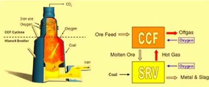
3.3.2 HIsarna Smelter technology
HIsarna is a bath-smelting based technology based on a combination of a hot cyclone for melting and smelter vessel for ore reduction and iron production. It also combines coal pre-heating and partial pyrolysis in a reactor, resulting in lower coal usage and thus reducing CO2 emissions. The flexible nature of the process would allow for partial substitution of coal by biomass, natural gas or even Hydrogen [14]. The HIsarna technology could be an option in the future for greenfield steel mills. HIsarna does not involve a recycling loop for the top gas, the oxidation of the smelter gas takes place at the cyclone level together with
Chapter 3
37
the combustion which supplies the heat to melt the ore. The cyclone is generated by the geometry of the reactor in its upper part, where crushed iron ore is injected together with oxygen. The heat generated in the cyclone ignites the initial partial reduction of iron ore to iron, which is separated from impurities by the centrifugal force of the cyclone. The molten iron then falls into the molten bath at the bottom of the reactor, where more oxygen and pulverized coal are injected and the reduction to pig iron is completed. The HIsarna technology eliminates the need of the pelletization step, thus removing the need of the sinter plant and eliminating all of its related CO2 emissions.
Figure 14 HIsarna reactor
3.3.3 ULCORED
ULCORED is a direct reduction process that produces DRI from natural gas or from coal
gasification. The off-gas from the furnace is recycled into the process after CO2 has been
captured and is ready for transport and storage. The reduced iron is a solid state a further step is necessary to melt the iron in an EAF. This technology has the advantage of eliminating the coke ovens, however it is presently more expensive than a conventional blast furnace and the amount of electricity required for melting makes the process less energy-efficient. It still is an attractive option where natural gas is available at a low price.
38
Figure 15 ULCORED with natural gas [16]
3.3.4 Alkaline Electrolysis
Electrolysis steelmaking technologies would allow to the transformation of iron ore into metal and gaseous Oxygen using only electrical energy [14], thus eliminating coke ovens and blast furnaces and all the related emissions. The most promising electrolysis processes for iron production studied by ULCOS are ULCOLYSIS and ULCOWIN. ULCOLYSIS operates at 1600°C with a molten salt electrolyte made of slag. ULCOWIN operates slightly above 100°C in water alkaline solution populated by small grains of ore [2]. These
processes, which could potentially be zero emissions if CO2-free electricity was available,
are still at a laboratory scale, since they have been thought developed by ULCOS for the first time, so a long time will be required to make available at a commercial scale.
4
THE INTEGRATED STEEL MILL MODEL
In chapter is presented the Integrated Steel Plant model, developed using GS Gas-Steam Cycle Simulation Code. The model comprehends the three main units of an Integrated Steel Mill: the Coke Oven, The Blast Furnace and the Basic Oxygen Furnace. The model simulates all the mass and energy balances, the chemical reactions and the transformation that take place inside the plant. The simulation computes mass flow rates and compositions of the steel mill off-gases, allowing to estimate the plant emissions. The model has been validated through confrontation with the Steel Mill model published in the International Energy Agency report [8].
4.1 The Coke Oven Plant Model
In the Coke Oven, coke is brought to 1000-1100°C in an oxygen-free atmosphere to realize the transformation process known as Pyrolysis. The Pyrolysis process transforms coal into coke, this transformation is accompanied by the release of gaseous matter that collects at the top of chamber. The off-gas is then processed to be cleaned and to recover valuable by-products such as Tar and Light Oil (BTX), the residual gas is called Coke Oven Gas; raw
40
COG has a relatively high calorific value and can be used as fuel both in the Coke Oven or in other units of the steel mill. Figure 16 shows represents the input and output flow of a coke oven at their typical temperature.
Figure 16 Coke Oven
4.1.1 Coke Oven
The model consists of two units: the actual coke oven, where the chemical conversion of coal into coke takes place, and the combustion chamber, where a mixture of Blast Furnace Gas enriched with Coke Oven Gas to increase the calorific value, is burned to supply the heat needed to sustain the high temperature Pyrolysis reaction. Coke Oven chambers receive the heat needed to sustain the high temperature Pyrolysis reaction from refractory heating walls, which are heated up by the hot flue gas, produced by the combustion of COG and BFG, flowing on their other side. The complex thermochemical conversion of coal is modeled by a chemical reactor component which computes the amount of heat needed to sustain the reaction. Figure 17 shows the design of the coke oven plant model, showing streams and their temperature.
Chapter 4
41
Figure 17 Coke Oven Model
At the chemical converter output the temperature must be imposed. Pyrolysis is considered complete when the core of the coke has reached 1000 – 1100°C [3]. Throughout the process gas is released at various stages, the most important of which is around 700-800°C resulting in a similar top gas temperature. In the model only one flow is allowed at the chemical reactor output, so the outlet temperature is imposed to be 1100°C, then, after separating the coke, the top gas flow is brought to its output temperature of 700°C pre-heating the coal before it is fed to the chemical reactor. Assumed temperatures and compositions, the model is able to compute the amount of heat required by the process. Coke is composed by the fixed carbon of the coal, the coal ashes and sulfur. In the model it is separated by three consecutive splitters that split respectively all the solid carbon, the sulfur and the ashes present in the chemical converter output flow. For simplicity Tar and
Light Oil have been considered as 100% Benzene (C6H6), a reasonable assumption
considering the marginal role of these compounds in the process and that won’t affect the results of the simulation. Indeed Tar and Light Oil are generally mainly composed by Benzene (C/H = 1/1), Toluene (C/H = 7/8) and Xylene (C/H = 8/10) so the resulting average Carbon over Hydrogen ratio is very close to the 1/1 ratio of the main compound; Tar has a Higher Heating Value around 36 MJ/kg and Light Oil around 44-46 MJ/kg, so it is reasonable to assume their mixture as 100% Benzene which has a HHV of 42.3 MJ/kg. After leaving the pre-heating heat exchanger at a fixed temperature of 700°C, the gas flow
42
goes into the cleaning and separation process where C6H6, water and H2S are separated from the main flow and the remaining gas is known as Coke Oven Gas. COG is then split in 2 separate flows, one of which is mixed with Blast Furnace Gas and sent to the Coke Oven combustion chamber, where the mixture will serve as fuel.
We chose to calibrate the model referring to [8]. The chemical reactor, given the input coal temperature and composition and the number of chemical species in the outflow, requires a number of constraints, which are given as ratios of the chemical compounds in the output flow, equal to the difference between the number of chemical species and the number of atomic species. Thus known the COG composition from [8], the constraints at the chemical reactor output were imposed, as shown in Table 1.
Table 1 Chemical Converter Imposed Ratios [vol/vol] H2/CH4 2.584 CO/CO2 4.000 N2/O2 30.32 CH4/CO 6.000 S/H2S 2.381 CH4/C6H6 6.700 CH4/C4H8 13.00 C4H8/C2H6 2.000
Coke is formed from the fixed carbon of coal, all the coal ashes and part of its sulfur. As
explained before Tar and BTX were assumed to be 100% C6H6. The S/H2S ratio serves to
identify the amount of sulfur that turns into H2S and leaves the chamber with the top gas
and the amount that remains in the coke. As coke producers use many different coals and coal mixtures to enhance the quality of coke, according to availability, price and coke quality requirements, a standard coking coal with a LHV of 31.3 MJ/kg has been chosen to be used as input coal in the model. The composition of the coking coal is showed in Table 2.
Chapter 4
43
Table 2 Coking Coal composition composition [% w] C 77.3% H 4.58% O 3.38% N 2.27% S 0.84% ash 9.88% H2O (moist) 1.81%
Table 3 and Table 4 show the results obtained by the model in terms of mass flows and COG composition in comparison to [8]. The accordance between computed results and source data allows to consider to model validated.
Table 3 Coke Oven Plant mass flows
[kg/TP] [8] model COKING COAL 1285.2 1286.66 COKE PRODUCED 1000 1000 COG PRODUCED 181 180.23 TAR 53.2 53.7
Table 4 Coke Oven Gas composition [%v]
[% v] [8] model CH4 24.0% 24.3% OTHER HC 2.80% 2.80% H2 62.0% 62.8% CO2 1.00% 1.01% CO 4.00% 4.05% O2 0.20% 0.16% N2 6.00% 4.93%
44
4.1.2 Coke Oven Combustion Chamber
The combustion chamber is modeled by a combustor unit, whose hot flue gas then serve as heat source for the chemical reactor, transferring heat to the chemical converter unit without taking part in the reaction. A parameter is set to represent the Coke Oven heat loss as a percentage of the heat transferred to the chemical converter (10%). The refractory walls of coke ovens are usually at temperatures between 1350°C and 1150°C, since in the model the output temperature at the chemical reactor is set to 1100°C the temperature of the flue gas at the outlet should be 150-200°C higher. Figure 18 represents the typical layout of the coke oven heating system.
Figure 18 diagram of a coke oven heating system [7]
The flue gas leaves the coke oven at a still high temperature which allows to pre-heat the fuel and the combustion air. Pre-heating is necessary to obtain a high flame temperature which would not be achievable without pre-heating because of the low heating value of the BFG-COG mixture. The model is set up to achieve the same fuel mass flow rates as [8]. COG mass flow is imposed and the BFG mass flow is enforced by the imposed COG/BFG
Chapter 4
45
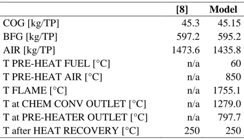
mass ratio. The resulting temperature reported in Table 5 are in accordance to the real physics of coke ovens, where the walls are kept in the 1350 – 1150°C range; thus the 1755.1°C at the coke oven inlet and the 1279.0°C at the outlet can be considered accurate (Coke leaves the coke oven at 1100°C). The combustion air mass flow is modified by the model to enforce an oxygen percentage in the flue gas of 5% as in [8].
Table 5 Coke Oven Combustion Chamber
[8] Model
COG [kg/TP] 45.3 45.15
BFG [kg/TP] 597.2 595.2
AIR [kg/TP] 1473.6 1435.8
T PRE-HEAT FUEL [°C] n/a 60
T PRE-HEAT AIR [°C] n/a 850
T FLAME [°C] n/a 1755.1
T at CHEM CONV OUTLET [°C] n/a 1279.0
T at PRE-HEATER OUTLET [°C] n/a 797.7
T after HEAT RECOVERY [°C] 250 250
Coke ovens always include regenerators to improve energy efficiency and are often followed by a heat recovery system to exploit the residual energy content in the flue gas, which leaves the pre-heater at a still high temperature. The model includes a heat recovery system and the outlet temperature is imposed to be 250°C as in [8].
46
4.2 The Blast Furnace Model
The Blast Furnace is the main and most complex unit of the Integrated Steel Mill model. In the BF a thermochemical process reduces iron ore to metal iron and melts the charge, to obtain a liquid hot metal called pig iron. A flow of solids, loaded at the top of the reactor, moves downwards towards the bottom reacting with a countercurrent of reducing gases. Together with iron materials and additives, coke is fed at the top of the reactor as the main reducing agent. At the bottom, a hot flow of oxygen-enriched air is injected. The reaction between air and the reducing agents produces carbon monoxide (CO), which plays the most important role in the Blast Furnace, reducing iron oxides to metal iron. Potentially any Hydrocarbon could be used as reducing agent in order to produce CO, but coke is used because it does not only serves as reducing agent, but it plays a very important structural role in the Blast Furnace operation staying solid and carrying the weight of the load because of its higher melting point. Moreover it serves as a fuel providing heat to melt the iron. At the tuyère level the temperature is high enough to melt the remaining coke, whose carbon joins the liquid hot metal producing pig iron. The request of coke can be reduced by using other reducing agents such as coal, oil or natural gas which can be injected on the tuyère level producing an economic operational advantage. Pulverized Coal Injection (PCI) is the most commonly adopted technique worldwide and is the one used in our model as well. Besides reducing the coke consumption it brings improved flexibility in the Blast Furnace operation and higher productivity, however it needs a higher air blast oxygen enrichment. A CO and CO2 rich gas (Blast Furnace Gas) is collected at the top of the furnace; although its residual calorific value is low, it comes in large amount and can be used to fulfill many power and heat requests throughout the plant. This gas, due to its high
carbon content and the large amount produced is the largest source of CO2 emissions in the
Chapter 4
47
Figure 19 simplified scheme of a blast furnace [7]
To produce a high quality steel with low impurity content, slag forming additives, mainly Limestone, are fed at the top of the furnace together with the rest of the solid load. Limestone is important to the process as it is the primary raw material which helps remove impurities from the iron ore and produces a slag with low melting point and a high fluidity. Limestone will react with the temperature in the blast furnace as it continues down the furnace to react with sulfur from the iron and produce a slag with the silica formed from the iron ore.
4.2.1 Chemistry of the Blast Furnace
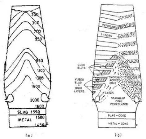
As shown in Figure 20, the materials inside the Blast Furnace assume a thermal profile during the operation, that can lead to identify temperature-zones in which certain reactions are dominant. Although the real physics and chemistry of the reactor are complex and don’t strictly follow zones but take place more as a continuous process, local conditions
48
and temperature in each zone increase favor certain chemical reactions. It is therefore useful to identify this zones, to outline the functioning of the reactor and model it.
The Blast Furnace can be divided into six main zones where the main chemical reactions between the two flows (the solid materials moving downwards and the gases climbing to the top of the furnace) take place. [17]
Figure 20 Thermal profile (a) and state of the material (b) in a Blast Furnace
Zone 1: from the top to 400°C
No chemical reactions take place, only heat transfer between the flows. The solid load is heated up to 400°C by the residual top gas before it leaves the furnace at a temperature usually in the 150 – 300°C range. The moisture in the solid load evaporates and leaves the reactor together with the top gas flow.
Zone 2: from 400°C to 800°C
This zone is characterized by indirect reduction reactions. Iron oxides are progressively reduced by CO carried in the gas flow according to the following exothermic reactions:
Chapter 4
49
3 Fe2O3 + CO ↔ 2 Fe3O4 + CO2 + 63.0 kJ (1)
Fe3O4 + CO ↔ 3 FeO + CO2 + 22.4 kJ (2)
FeO + CO ↔ Fe + CO2 + 13.2 kJ (3)
Reaction (1) achieves a high conversion already at 400°C, indeed as you can see in Figure
21, the line representing the Fe2O3-Fe3O4 equilibrium is not even shown for temperatures
higher than 400°C, we can thus assume that reaction (1) can achieve complete conversion at this zone’s temperature even at low CO concentration. However to achieve complete conversion of reactants into products in reaction (2) at these temperatures a large excess of CO is needed. As shown in Figure 21, in this environment, the equilibrium of the Boudouard reaction (4) is leaning towards the right, in the sense that the CO2 that is generated by the iron reduction reactions, doesn’t react with Carbon to produce more CO, conversely, although to a lesser extent, CO is converted into CO2 and C.
2 CO ↔ CO2 + C + 172 kJ (4)
Figure 21 Iron oxides equilibrium curves and Boudouard curve as function of temperature
50
In a minor scale indirect reduction reactions involve hydrogen reacting with iron oxides according to these reactions:
1/2 Fe2O3 + 3/2 H2 ↔ Fe + 3/2 H2O + 48.95 kJ (5)
1/3 Fe3O4 + 4/3 H2 ↔ Fe + 4/3 H2O + 51.04 kJ (6)
Zone 3: from 800°C to 1350°C
Direct reduction becomes dominant at this temperature range. Together with the iron oxides reduction reactions (1-3) the following endothermic reaction, triggered by the higher temperature takes place consuming the C in the coke:
CO2 + C ↔ 2 CO - 172 kJ (6)
The CO2 produced by iron reduction reactions reacts with the carbon in the coke,
producing more CO that reduces the iron oxides thus, globally, the name direct reduction. Reaction (6) is largely endothermic, resulting in an overall slightly endothermic process in this zone.
The limestone dissociation also occurs in this zone, another endothermic reaction causing an increased heat absorption:
CaCO3 ↔ CaO + CO2 - 178 kJ (7)
CaO is very important for the blast furnace operation because it clears impurities from the iron, creating the slag. The lime dissociation reaction requires a great amount of heat, therefore sometimes, to reduce the energy demand of the blast furnace, lime can be produced separately and fed directly to the Blast Furnace.
Zone 4: from 1350°C to 1600°C
Silicon and manganese oxides are reduced and in part merge with the iron, which starts melting in this zone forming cast iron, together with carbon. Silicon and manganese reduction are never completely advanced, thus the non-reacting part is absorbed by the slag.
![Figure 1 Contribution of technologies and sectors to global cumulative CO2 reductions [5]](https://thumb-eu.123doks.com/thumbv2/123dokorg/7522394.106187/12.892.137.728.448.674/figure-contribution-technologies-sectors-global-cumulative-co-reductions.webp)
![Figure 3 Annual world steel production [10]](https://thumb-eu.123doks.com/thumbv2/123dokorg/7522394.106187/18.892.232.640.118.348/figure-annual-world-steel-production.webp)
![Figure 7 General view of two blast furnaces [7]](https://thumb-eu.123doks.com/thumbv2/123dokorg/7522394.106187/23.892.166.751.247.595/figure-general-view-blast-furnaces.webp)
![Figure 11 SEWGS principle: (upper) adsorption and reaction at high pressure (lower) desorption at low pressure [21]](https://thumb-eu.123doks.com/thumbv2/123dokorg/7522394.106187/32.892.153.705.623.803/figure-sewgs-principle-adsorption-reaction-pressure-desorption-pressure.webp)
![Figure 13 Top Gas Recycling Blast Furnace [15]](https://thumb-eu.123doks.com/thumbv2/123dokorg/7522394.106187/36.892.190.680.333.796/figure-top-gas-recycling-blast-furnace.webp)
![Figure 15 ULCORED with natural gas [16]](https://thumb-eu.123doks.com/thumbv2/123dokorg/7522394.106187/38.892.232.638.133.397/figure-ulcored-with-natural-gas.webp)
![Table 1 Chemical Converter Imposed Ratios [vol/vol] H 2 /CH 4 2.584 CO/CO 2 4.000 N 2 /O 2 30.32 CH 4 /CO 6.000 S/H 2 S 2.381 CH 4 /C 6 H 6 6.700 CH 4 /C 4 H 8 13.00 C 4 H 8 /C 2 H 6 2.000](https://thumb-eu.123doks.com/thumbv2/123dokorg/7522394.106187/42.892.298.572.489.711/table-chemical-converter-imposed-ratios-co-ch-ch.webp)