Laurea Specialistica in Ingegneria Informatica
Improving security and memory management in
the MUSCLE card framework
Relatore:
Laureando:
Prof. Paolo Ancilotti
Emanuele Gringeri
Prof. Giuseppe Anastasi
Correlatore:
Dott. Tommaso Cucinotta
sia pure per un attimo?. . . ”.
(Ivan S. Turgenev)
Alla mia famiglia
When we talk about security in reference to a computer system, we talk about all the facilities and features needed to avoid that unauthorized people are capable to access to sensitive data. Security is a crucial matter and it is achieve in different way, one of those is cryptography. Cryptography allows to protect user data as long as the keys used to crypt data are safe. A means to store in a secure way this information is constituted by smart card. Of the size of a credit card, they are provided with compute and storage capabilities. More powerful has been supplied with a dedicated hardware for cryptographic operations. In the past, development of smart card based applications, has been hindered by the lack of an open API, and this lack has been overcome with the efforts of Schlumberger to introduce Java Card. Despite this, the development process on open platforms was however hindered by the lack of drivers, specifications and documentations typically available for commercial platforms only. The aim of the MUSCLE card team was to give a way to spread this technology on open platforms. Today, the MUSCLE card framework is widely used in the open source community, allowing users to sign document by means of a smart card device. Aim of this master degree thesis is to overcome some limitation of this framework. After a brief presentation of Java Card, MUSCLE Card and related concepts, we discuss the state of the art of the framework, the proposed modifications and how these has been brought.
1 Introduction 1
1.1 Cryptography in brief . . . 1
1.2 Smart Card Beginning . . . 4
1.3 Java Card . . . 6
1.4 MUSCLE card . . . 7
1.5 Project purpose . . . 8
2 Java Card 11 2.1 Java Card Applet . . . 11
2.1.1 Java Card Applet lifetime . . . 12
2.2 JCRE lifetime . . . 14
2.3 Working with APDU . . . 16
2.4 Java Card Objects . . . 18
2.4.1 Persistent object . . . 19
2.4.2 Transient object . . . 19
2.5 Atomicity and transactions . . . 20
2.5.1 Atomicity . . . 20
2.5.2 Transactions . . . 20
2.6 Firewall and Object Sharing . . . 21
2.6.1 Applet firewall and contexts . . . 21
2.6.2 Object sharing across contexts . . . 21
2.6.3 JCRE privileges and entry point . . . 22
2.7 Exceptions handling . . . 22
3.2 Input and output objects . . . 25
3.3 Security model and access control enforcement . . . 27
3.4 PIN management . . . 28
3.5 Host-side architecture . . . 28
3.5.1 API function set . . . 29
3.6 MUSCLE card PCSC Lite API . . . 31
3.7 MUSCLE card PCSC IFD Driver API . . . 31
3.8 CT API . . . 31 4 PCSC 33 4.1 Introduction . . . 33 4.2 Architecture overview . . . 34 4.2.1 ICC . . . 34 4.2.2 IFD . . . 34 4.2.3 IFD-Handler . . . 35
4.2.4 ICC resource manager . . . 35
4.2.5 Service Providers . . . 36
4.2.6 ICC-aware application . . . 38
5 Java Card Emulator 39 5.1 Implementation details . . . 40
5.1.1 JCRE . . . 40
5.1.2 CAD . . . 40
5.1.3 ClassLoader and JCManager . . . 42
5.1.4 The installer . . . 43
5.2 Java object serialization . . . 44
5.3 Java Card Packages . . . 45
5.3.1 javacard.framework . . . 45
5.3.2 javacard.security . . . 46
5.3.3 javacardx.crypto . . . 46 v
5.4.2 Cryptographic Service Provider . . . 47
5.5 JCEmulator update . . . 48
6 PKCS #11: Cryptographic Token Interface Standard 49 6.1 PKCS #11 users . . . 50
6.2 PKCS #11 sessions . . . 51
6.3 PKCS #11 security considerations . . . 52
7 MUSCLE card: on-card applet 54 7.1 MUSCLE: the state of the art . . . 54
7.1.1 Memory Manager . . . 54
7.1.2 Object Manager . . . 56
7.1.3 CardEdge . . . 58
7.2 Overcome the short limitation. . . 61
7.2.1 Ulong - unsigned long . . . 61
7.3 MemoryChunk class . . . 65
7.4 The proposals modifications to the original package . . . 66
7.4.1 Memory Manager . . . 66
7.4.2 Object Manager . . . 68
7.4.3 CardEdge . . . 73
7.5 Enhanced Security Model . . . 74
7.5.1 Enhanced Security Model: an example . . . 78
7.6 PKCS11# module . . . 78
8 Host-side framework 82 8.1 Enhanced Security Capabilities . . . 83
8.2 Key blobs . . . 83
9 Test and applications 85 9.1 MUSCLE tool . . . 87
3.1 Association between identify, PIN and cryptographic key numbers . . 27 3.2 Some ACWs and their meanings . . . 28 6.1 Access to Different Types Objects by Different Types of Sessions . . . 52 7.1 Methods to manage integer in ulong representation . . . 63 8.1 PL MSCSetKeyACL C-APDU . . . 83 8.2 PL MSCSetObjACL C-APDU . . . 83
2.1 Application identifier - AID . . . 11
2.2 Java Card life cycle . . . 14
2.3 On-card system architecture . . . 15
2.4 Command APDU structure . . . 17
2.5 Response APDU structure . . . 17
2.6 Command and Response APDU case 1 . . . 17
2.7 Command and Response APDU case 2 . . . 17
2.8 Command and Response APDU case 3 . . . 18
2.9 Command and Response APDU case 4 . . . 18
3.1 The ExportKey . . . 26
3.2 The MUSCLE card framework architecture . . . 29
4.1 General architecture . . . 34
4.2 Service Providers . . . 37
4.3 ICC/PC Communication layers . . . 38
5.1 Java Card Simulator architecture . . . 39
5.2 States of the server . . . 42
5.3 CAD Gui . . . 42
5.4 Installer Gui . . . 43
5.5 Installer Gui . . . 44
5.6 Java Cryptographic Architecture . . . 47
5.7 javacard.security.Key interfaces Class . . . 48
7.2 The MUSCLE Object header structure . . . 56
7.3 The MUSCLE card portion of the header of the object that contain the ACL . . . 57
7.4 Key ACL . . . 60
7.5 Setup APDU . . . 62
7.6 . . . 66
7.7 The proposal complete header . . . 68
7.8 The proposal reduced header . . . 69
7.9 Allocation of fragmented object . . . 72
7.10 Main and alternative object ACL . . . 76
7.11 Main and alternative key ACL . . . 76
7.12 Enhanced Security Model: an example . . . 78
8.1 Key blob header . . . 84
9.1 MUSCLE tool an example . . . 88
Introduction
1.1
Cryptography in brief
Nowadays, computer applications are ( becoming ) pervasive. As a matter of fact it is enough think about how these are employed in pursuance of the normal daily activities. E-mail, Instant Messaging (IM), but also fax machine, credit cards are, by now, parts of a more larger system that does not concerns only business. People, everyday, are involved in communications and they are entertained in connections with other people, connections that could be beyond the scope of business. However, whichever it is the way in which these applications are involved the idea of “security” is crucial. For “security system” we mean a system in which it is extremely hard people to do things they are not allowed to do. A common example of security system is a bank. In a bank, hopefully, you should not be able to withdraw, for instance, money from the account of someone else. One thing must be clarified. Talking about security in computer systems could be misleading. There are no completely secure computer system and when we talk about secure systems we talk about systems that are more or less secure. A more secure system is a system in which the costs in term of time and money needed to broke it, are comparable to the cost of the system itself. Just like for a system, the difficulty to broke a computer application must be balanced by the value of the application and of the data it manages. What I mean is everything that concerns security is serious business and it must be not relegated at the end of
a hypothetical list of things to do, when we are involved in the task of development of applications, but security should be part of the design from the beginning. Just think that the growth of Internet and, consequently, of the applications that works in the network are closely following the growth of computer crimes. So, the importance to protect information grows with the value of the information itself. Nobody wants to reveal the content of, for example, a confidential email or a conversation. One solution that can help us protecting information when these are traveling around the network is cryptography, the science of the secret writing. Cryptography is son of a branch of mathematics, cryptology (derived from Greek krypt`os ”hidden” and gr´afo ”write”) which have another son, cryptanalysis, which is the science of analyzing cryptography. Typically, every time the subject is cryptography we have two players in a stage: plaintext, data that we can read and understood without any further measures, and ciphertext that plays the role of a disguising plaintext. In other words ciphertext is something that at first sight we cannot understand. The operation that turns a plaintext in a ciphertex is usually called encryption while, the operation that, given as input a ciphertext, returns us the original plaintext is called decryption (or also known as encipher/decipher operation) and the leading man in the stage is ”Key”. Key enables us to achieve our goal. Confidentiality. It is not important how much is the value of message that we want to hide. Maybe we can avoid that that our sister reads our private e-mail or more simply we want to prevent major to put his nose in our business. All we want is confidentiality. The other goals of cryptography are:
- Authentication. The recipient should be in a position to ascertain the source of the message.
- Integrity. It is the guarantee that the message was not modified while it was in travel.
- Nonrepudiation. It is the impossibility for a sender to deny that he had sent the message.
Authentication, integrity and nonrepudiation are crucial in computer applications that are involving in social interactions because these guarantee that the interactions
are analogous to a face-to-face interactions.
Also we can distinguish between ”conventional or symmetric/secret key cryptog-raphy” and ”public key or asymmetric cryptogcryptog-raphy”. The former uses, as the name suggest, only one key for both the operations of encrypt/decrypt. When Caesar wanted to send a message to his general, obviously, he cannot trust the messenger so, typically, he does not send the original message but send a message in which every letter was shifted and the key to decipher the message is the value of the shift. The substitution cipher is one of the more ancient cipher system but, as we can suppose, today is too weak to adopt. The biggest weakness in symmetric cryptography is due to the need to share the key. So we need a secure channel to share the secret that allows other to decrypt the original message. Obviously we cannot go around the world with a briefcase handcuffed at our wrist to avoid the theft of the key. The issue of the key distribution is cleverly solved with the use of asymmetric cryptography. In this scenario every user is equipped with a pair of keys, where the two keys within each pair need to satisfy complex mathematical conditions in order for the system to work. One of the pair is called public key, while the other is a private key and both are used for achieve different purpose. For example, public key is used to crypt data while the private key is used to decrypt. The normal processes involved in the creation of the pair of keys are such that is infeasible ”calculate” the private key from the public key. This enables to share public key by web for instance, without the issue to establish a secure channel. The use of a public key scheme made possible the use of digital signature which use a hash-function and produce a message digest (i.e., a hash of the original message), the message digest is encrypted using the private key and then both can be send. The recipient uses the public key of the sender to retrieve the message digest of the message and compare this to the message digest obtained from the computing of the hash function of the original message. If the send and received message digest are not equal we can conclude that the message was tampered with. With the use of digital signature is achieve the goal of integrity and nonrepudiation. Authentication maybe achieved but we need some other shrewdness. Authentication, in fact, assures that the sender is who he says to be and, given the ease with which the key can be shared, everyone could, for instance, post a phony key with the name
of another user’s recipient. Data encrypted can be intercepted and decrypted by the owner of the bogus key. To counter this threat, man-in-the-middle threat, we need something that assured that the public key which we are using to encrypt data is the public key property of the recipient of the message. This ”something” is a digital certificate, whose purpose is establishing whether the public key belongs to a proper owner. A digital certificate contains the following information:
1 - A public key.
2 - Information about the Subject/Owner that ask for a certificate.
3 - One or more public key information. This attest that the public key is linked with certificate information, but not attest the whole certificate.
To share digital certificates, we need to put the sharing servers in a place where we can vouches for security and storage of the certificates. These servers can offer only storage and sharing services and they are also known as Certification Server or they can furnish more additional key management features and these are known as Public Key Infrastructures (PKIs). A certificate server is a database that allows people to upload and retrieve certificates. A PKI contains the facilities of a certificate server but also allow management features like those needed to revoke or trust a certificate. The more important feature of a PKI is a Certification Authority (CA), which is, usually, an entity, that an organization has authorized to issue certificates.
1.2
Smart Card Beginning
Although we may not notice that, it is just impossible that we have ever used a smart card. Just think that a credit card or, more simply, GSM SIM cards are, in different way, examples of smart card. A smart card is a card with computing capacity. It is equipped with a microprocessor and different kinds of memory
ROM - ROM is used to store fixed program as, for instance, operating system routines. As the name suggest it cannot be written after the card is manufac-tured.
RAM - RAM is not persistent and is used as working space for modifying data. The memory content is not preserved when the power supply goes off.
EEPROM - In a EEPROM like the ROM the stored data are preserved when power supply goes off with the distinction that content of the EEPROM can be modified.
Given the possibility to compute and store date, the use of this technology has been grown during the past years. Computational power and data storage are not the only benefits that the use of this technology bring. In fact ease of use, portability and security are other key features that we gain with the use of smart cards. The application fields of this technology are many, like payment and banking industries, in retail loyalty scheme, in health care sector, in automotive transportation, in campus university, and, obviously, in Internet. So we can use it to implement an electronic wallet (e-wallet ) in which the bank stores the electronic money and the balance can be increased or decreased depending on the operation. Using the card in a retail loyalty scheme we store loyalty points when, for instance, the owner of the card, purchases some gift from cobranded retail partnerships, and then using these points as point-of-sales discount. The data captured during the normal daily activities are used to make market segmentation. In health care scheme we can storage the clinical records of the patient like old surgery, allergies and insurance coverage information also. All the kind of information that can help the hospital to assert patients rights. In automotive transportation smart card, can be easily and quickly recharged and the credit could be used like parking or toll tokens. In a campus university we can use smart card for a wide set of applications, like grant access at the building after normal opening hours thereby allowing security and access control, borrowing books, pay laundry, canteen, but also for storing students records, grades, fees. On the internet smart cards are widely used in PKI infrastructure. The card stores the private key and a digital certificate, two components that verify the identity of the card’s owner. We can use smart card for digital signing of email, web access control and so on. Just a wonderful object but next question is, how does difficult is implementing these applications and see if these works on a smart card? Develop application for
smart card has been really difficult in the past time. In fact, even though the cards are standardized for what concern shape, size, contact, communication protocol, the way they operate differs widely from one manufacturer to another, and the absolute absence of standardized high-level development kits has hindering the development of third parties applications. In fact, most of smart card application had been developed from the ground up with a wide waste of time.
1.3
Java Card
One of the obstacles that most hindering the spread of smart card technology was the difficulty in applications development. The developer had to known the micro-controller instructions and, how we could imagine, this made write application for smart card a task for very skilled nerd. Nevertheless since November 1996 music changes. In fact, Schlumberger was working to allow everyone to write applications that can be used in a smart card. Their choice fall on Java and, during the same year the Java Card 1.0 draft was issued. Java Card technology allows application (applets) written in Java to ran on a smart card. The greatest challenge of the Java Card team is to fit a Java Card Virtual machine into a smart card saving enough space for applications. The Java Card VM is split in two parts. One part runs off-card and the other runs on-card, and all these tasks that do not require runtime constrains such class loading, bytecode verification etc., are delegated to the off-card virtual machine, where the resources are not a concern. Because of the split of the Java Card VM, distributed between smart card and host, the Java Card platform consists of three parts, Java Card VM that defines a subset of the Java language and a virtual machine suitable for smart card applications, a Java Card RE that describes the Java Card runtime behaviour, and Java Card API that abstract the hardware complexity making simple write applications. Benefits of the use of Java Card technology can be so summarized:
Ease of use - Working with high-level API, the developers of applications can concentrates their effort on the details of the application forgetting the beneath complexity.
Security - Security plays a key role in smart card and also in Java Card. In fact the access to methods and variables is strictly controlled and there is no possibility, for instance, to forge a pointer and harm the memory. Java Card has also a firewall that prevents that an object of the applet can gain access to the object of another applet. This prevent a hostile applet to harm our applet. Hardware independence - Java Card is also independent from beneath hardware. In fact Java Card applets are written on the top of the Java Card platform and therefore they are hardware independent allowing us to load directly into smart card without the need to recompile them.
Store and manage multiple applets - In a Java Card smart card we can host multiple applications. The firewall mechanism prevents the access of an instance of the applet to the object of another instance unless explicitly permitted. Compatibility - Java Card is based on ISO7816 standard.
1.4
MUSCLE card
MUSCLE - movement for the use of smart card in a Linux environment - proposes an SC framework working across different multi-vendor card devices and on open plat-form. At the bottom layer, readers are supported through drivers that implementing the IFC-Handler/CT-API interface. At the above layer, the pcsc-lite daemon is re-sponsible to manage the hardware SC-related on the PC, while the independence from the card is achieve thanks to a Card driver loader which loads the correct card driver according to ATR - (answer to response). To the upper layers, the MUSCLE API provides an open framework which components are designed in a generic way, in order to meet the needs of many applications. These needs have been recognized in generating, importing, exporting and using cryptographic key on the card and in creating, reading, writing generic data into the card to store, for instance, a PKI cer-tificate. The API have been summarized into six sets namely: session management, data storage, cryptography, PIN management, access control, miscellaneous. In brief,
the session management functions set allow an application to enumerate readers and inserted cards devices, as well as to manage connections with a smart card; data stor-age functions set encapsulate application data into container called objects identified by an object ID and, therefore, allows an application to create, read, write and delete objects; cryptographic functions set allow to manage keys operation like its genera-tion, importagenera-tion, exportation and, obviously, perform crypt/decrypt and sign/verify operation; pin management functions set allow to create, verify, change and unblock PINs. The resources on the card are protected by an access control list based model. In this model every operation is allowed only after the appropriate user authentica-tion. Three level of authentication are possibles, PIN code, challenge-response and a ”combination of both” mechanisms. The access rules are based on the concept of identity. We have 16 different identities every of which is associate to a PIN or to a cryptographic key. In detail the identities which are numbered between 0 (zero) and 7 are labelled as PIN-based and these are associate with PIN codes 0-7; identities be-tween 8 and 13 are strong identities and these are associated with cryptographic keys 0-5; identities 14-15 are reserved for future use. In every session with a smart card we keep track of every single attempt of authentication and the current set of identities logged-in represents successful attempt of authentication of the single identity. The use of identities allow an application to grant access a high level resources. The ACL specifies which identities are required to gain access to objects and keys. Every ACL consists of three ACW, which is composed of 16 bits and each bit corresponds to one identity. The all zero ACW have the means of ”always allowed operation”, while an all one ACW have the means of ”disabled operation”. Summarizing, an operation can be always performed if the ACW not required authentication, PIN protected if the ACW required PIN verification, strongly protected if the ACW required a strong authentication and disabled if the ACW is all-ones.
1.5
Project purpose
The aim of this master degree thesis is to bring a set of modifications to the MUSCLE card framework in order to extend, enhance and, somewhat complete the functionality
supplied. These changes affect the MUSCLE card framework in several areas:
Memory management for the on-card applet: due to the limited computing capacity, Java Card supports only a restricted set of data types and structures and, because of those, it is not possible to allocate more than 32767 bytes of memory. Our efforts have been intended to overcome this limitation.
The access control model for the on-card applet, gives a means to allow the execution of an operation only if all the required identities has been successfully verified. To develop different and more complex scenarios a new, alternative, ACL has been introduced. This allows us to enforce the security policy.
PKCS#11 support: the standard increases the security of the objects allowing operations only after that users supplies a PIN and by means of a set of flags. To enhance the security the following flags have been introduced:
– CKA ALWAYS AUTHENTICATE requires that the user supplies the PIN for each use of the key. Default is false.
– CKA NEVER EXTRACTABLE is true if the key has never the CKA EXTRACTABLE flag set to true.
– CKA EXTRACTABLE true if key is extractable.
JCEmulator gives a means to allow developers to test their applications without the need to download the applet on the card. The emulator has been extended to support:
– DES - to allow the generation of a DES key.
– RSA - to allow the generation of a pair of RSA keys. – DSA - to allow the generation of a pair of DSA keys.
Support for related crypt/encrypt algorithms has also been added.
The MUSCLE card framework plays a key role in open source environment, when smart cards are needed. The MUSCLE card framework is open and this means
that everybody in the earth that need this software can take advantage of it, in his original form or bringing modifications in order to meet several needs. The wide use in the open source context, helps developers learning about goodness of the software, fixing bugs and so on. The open source community emphasizes also lacks of different functionality. The idea of this thesis arise from some of this necessities.
Java Card
2.1
Java Card Applet
Not to be confused with Java applets, Java applications written to run in a web browser environment, Java Card applets are Java programs written so that it adheres to a set of constrains that allow the post-issuances loading applets and their execution in a real smart card. The applet convention has been adopted to give the possibility to load a Java Card program into a Java Card runtime environment after that the card has been manufactured unlike what happened for applications in many embedded system. Every class must extend from the javacard.framework.Applet class. The Java Card runtime environment supports a multiapplication environment. So, in the same card we can run multiple instance of the same applet or different applet.
Figure 2.1: Application identifier - AID
As well as Java programs, which are uniquely identified using unicode strings and naming scheme based on a Internet domain, Java Card applet are also uniquely identified with a string, called application identifier - AID, which is split in two parts: the former, called resource identifier - RID is make up of 5 bytes. RIDs are unambiguous for each vendor and the control of their assignment is task of ISO. RID
identifies the applet provider on the card. The latter, is called proprietary identifier extension - PIX. A PIX can be between 0 to 11 bytes long. The AID is the results of the RID and PIX concatenation. Development of a Java Card program is not more different from develop a Java program. Just like a Java program we can start writing our classes, compiling these and, as well as we can imagining we obtain a set of class files. Using normal Java tools we can easily test and debug our application in every aspect without going through the conversation step. Obviously some Java Card features like Java Card firewall and transient and persistent object behaviour cannot be analyzed. Then, the class files are converted in a CAP file. This file, obtained from the step of conversion, represent the applet. We can now use this CAP file to test the applet in a simulated Java Card runtime environment. The behaviour of the application should be the same of the application running on a real card. Finally, after every debug steps the applet should be ready for the download into card. This step, called ”installation”, refers to the process of download of the CAP content into the card and, then, the creation of an applet instance to bring it into a selectable and execution state. To load the applet into the card, the off-card installer transforms the CAP file in a stream of application protocol data unit - APDU commands. The on-card installer writes the content of these APDUs in the persistent memory and, at least, instantiates the applet and registers the instance with the JCRE. From now on, the applet can be selected and executed. Once selected, the applet waits for a command from the host side, executes the command and returns the results of the execution to the host.
2.1.1
Java Card Applet lifetime
Install method
The install method uses the operator new to create an instance of the applet and then make a call to the constructor of the applet. It is highly recommended that every object needed to the applet during its lifetime cycle is instantiated and initialized into the constructor. This reduce the possibility of ”applet failure” due to lack of memory. Summarizing, the stream of the constructor must consist of:
Create the objects that the applet needs during its lifetime cycle. Initialize objects and internal variables
Register the applet with JCRE calling the register method.
A call to the register method, mark the beginning of the applet lifetime cycle. The installation phase, make up of the invocation of the install and register method, is considered successful if no issue occurring during the previously mentioned method. If a failure occurs during the install method and prior of the register method, the JCRE will perform every cleanup operation to reclaim the on-card resources, therefore JCRE delete the instance of the applet as well as every object previously allocated. Therefore, it is important that the method register is the last invoked method during the installation phase. Register method has two functions. First store a reference to the applet with JCRE and, second assign an AID to it.
Select method
Until the select method has not been invoked the applet remains in a ”suspend” state. Applet selection occurs when the SELECT APDU command, the only Java Card standardized command, is received and successful processed. Receipt of a SELECT APDU causes the invoking of the method select. If the selection fails, JCRE returns the status word 0x6999 to the host, otherwise, true is returned and the SELECT APDU command is passed to subsequent process method and there the APDU content is examined.
Process method
From now and until the method deselect is invoking, every received APDU is ex-amined into the process method. This method is abstract and it must be, directly or indirectly, overridden. Typically this method is implemented as dispatcher. The method examines the APDU header and it calls the corresponding method to execute the request function.
Figure 2.2: Java Card life cycle
Deselect method
The select method allows the applet to perform every cleanup operation before to go down and permit to another applet to be selected. The method is abstract and the applet must override the method and supplies every required cleanup operations. In spite of the method could fails the applet will be always deselected and another applet could be selected. Every exception in deselect method will be ignored. Power loss or reset card causes applets deselection despite the method deselect has not been invoked.
2.2
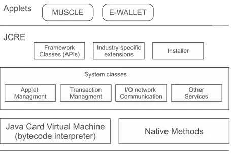
JCRE lifetime
The on-card system architecture is organized on three-layers. The bottom layer con-tains smart card hardware and native system. The middle layer concon-tains the JCRE that consist of Java Card Component running inside the card. It is responsible of the management of resources, communication, applet execution etc. The bottom layer of the JCRE consists of the JCVM that executes bytecodes, and some native methods that are responsible for handling low-level capabilities. The middle layer of the JCRE contains system classes. They manage transaction, communication, applet creation, selection and deselection. Top layer consist of Java Card API, industry-specific ex-tensions and the installer that gives a way to load apples into the card. The top layer of the architecture consists of Java Card applets. Software written in a subset of Java
Figure 2.3: On-card system architecture
programming language, thought to permit the writing of user application that can fit in a smart card. The JCRE is initialized at card initialization time and is performed once in the card lifetime. During the initialization are created all the objects used to support JCRE services and manage applet. During the normal use of the card, if the power is removed the JCRE suspend the execution of the JCVM. Then, when the power supply is applied, the JCRE restarts the JCVM by the main loop and not from the point of suspension. So we can think about the JCRE like a operating system running inside the card whom lifetime is tightly linked with the lifetime of the card. Some JCRE features are
Persistent and transient objects managing. Atomic operations and transactions.
2.3
Working with APDU
In smart card world, the communication between card and host is employed following the master-slave model in which, as we may simply imagine, the role of the card is always passive, waiting for command APDU from the host. It executes the command specified in the APDU and it replies to the host with a response APDU. As specified in ISO 7816-4, an APDU message comprises two structures, both of them used in a different communication side: one, referred as command APDU (C-APDU), used by the applications host side and, the other, also known as response APDU (R-APDU) is used by the card to send response back to the host applications. The command APDU structure, consist of two parts. The former, a mandatory header, consists of 4 bytes:
CLASS - The class of instruction identifies a category of command and response APDUs. INS - The instruction byte specifies the instruction of the command.
P1 - The first parameter is used to provide a further characterization of the instruc-tion.
P2 - The second parameter is used to provide further characterization of the instruc-tion.
The latter, an optional body, varies in length. Its fields are: Lc - This field specifies the length of the incoming data, in bytes.
Data - This field contains data incoming to the card for the execution of the instruction specified in the header.
Le - This field specifies, the number of bytes expected by the host response.
Every command APDU is always followed by an response APDU. The response APDU consist of two parts too: one mandatory and one optional. The mandatory fields (trailer) consists of two fields SW1 and SW2, called in conjunction status word.
Status word gives information about the state of the execution of a command APDU. In the optional body, the data field carry back data to the host. The following pictures show the C-APDU and R-APDU structures:
Figure 2.4: Command APDU structure
Figure 2.5: Response APDU structure
APDUs can be categorized, based on whether a data field is contained in C-APDU or R-APDU.
In case 1, the command APDU contains only the header and the response APDU contains only the trailer status word:
Figure 2.6: Command and Response APDU case 1
In case 2, no data are transferred to the card, but data are returned back. The command apdu contains the Le byte that specifies the number of data bytes in the data field of the response APDU.
In case 3, data are transferred to the card, but no data are returned from the card. The command APDU includes the Lc fields and the data field. The response APDU contains only the trailer status word.
Figure 2.8: Command and Response APDU case 3
In case 4, data are transferred in both sides. The body of the command APDU contains the Lc field, the data field, and the Le filed. The response APDU contains both the data and the trailer status word.
Figure 2.9: Command and Response APDU case 4
Applets on card and host side applications cannot communicate directly, but it interacts through the JCRE. Every communication between the host and the card take place through exchange of APDUs. JCRE creates an APDU object and it places the content of the message in an internal bytes array also known as APDU buffer. The APDU object, instance of the APDU class, could be thought as a communication object. When an APDU from the host is received, the content is copied into the APDU buffer, the method “process” is invoked by JCRE and the APDU object is passed as parameter. After the processing of the corresponding method, if the applet wants to give back data, it can use the APDU object to do so. The response is written in the APDU buffer and the content is sent back to the host.
2.4
Java Card Objects
Objects in Java Card are used to store, represent and manipulate data. They are sub-ject to the Java rules and, therefore, they have the same root class (java.lang.Obsub-ject)
and they are initialized to their default value unless is not differently specified. Java Card supports both persistent and transient objects.
2.4.1
Persistent object
A persistent object survives across CAD sessions. A persistent object have the fol-lowing properties:
A persistent object is created by the new operator
A persistent object hold states and value across CAD sessions
Any update to a single field is atomic. If an error occurs during the update, previously value is restored.
2.4.2
Transient object
The term transient referred to a Java Card object can be misleading. In fact with this term we mean a temporary object that will be destroyed when the power is removed. It is not exactly this. When we talk about transient objects we talking about objects which content is temporary and, for instance, when the power is re-moved, all the fields of the object are cleared but, like for the persistent object, the allocated space is reserved and cannot be reclaimed unless a garbage collector was implemented. The write cycles that involve fields of a transient object are not cause of performance penalty, because the RAM has much more faster write cycle time than EEPROM. The transient objects are ideal for small amounts of data that are frequently modified and there is no need to preserve it across CAD sessions. By rule of thumb if temporary data are being updated multiple times for every APDU processed, it is better move them into a transient object. There are two types of transient ob-jects: CLEAR ON RESET and CLEAR ON DESELECT. The former preserves data across applet selections but not across card reset. The latter preserves data until the deselction of the applet or card reset. Because a card reset event implicitly dese-lect the current sedese-lected applet, the field of CLEAR ON DESELECT objects are also
cleared on a CLEAR ON RESET event. In other words CLEAR ON DESELECT objects are also CLEAR ON RESET objects.
2.5
Atomicity and transactions
Nowadays smart cards are widely used for storing personal data and giving authen-tication services but, anytime, during the execution of an applet the risk of failure is around the corner. Just think that involuntarily you can remove the card from the CAD, cutting off the power supply and so on. All this events would leave the fields of an object, involved in an operation, in a insubstantial state if a robust mechanism to ensure atomicity was not supplied. JCRE support the atomicity mechanism at two levels. First, the Java Card platform guarantees that any update to a field of an persistent object is atomic. Second, it supports a transactional model in which an applet can group a set of updates into a set of atomically updates.
2.5.1
Atomicity
With the term atomicity, on the Java Card platform, we mean that any update to a single field of an object is guaranteed to either complete successfully or be restored to its original value if an error occur during the update. The JCRE atomicity is, obviously, applied only to persistent objects.
2.5.2
Transactions
If an applet needs to update several fields in different objects atomically, like for example the update of the “number of transaction” and “purse balance” fields in a debit transaction, we can use a transaction. Like in a database context, the Java Card platform supports a transaction model with commit and rollback capability to guarantee that an operation that involves the update of more fields can be performed atomically. Transactions can be aborted either by the applet or by the JCRE. If an applet abort a transaction the JCRE throw away any changes made and restore the value of the objects to their previously value. If power is lost or an error occurs during
a transaction, the JCRE invokes the rollback facility to restore the previously value of the object involved during the transaction. In both cases, to restore the previously objects value, JCRE uses an internal buffer, called commit buffer in which are stored both the object value and some overhead. Due to limited capacity nested transactions are not allowed and a exception is thrown.
2.6
Firewall and Object Sharing
Brief description of the protection and secure object sharing mechanism.
2.6.1
Applet firewall and contexts
Java Card is a multiapplication platform that allows multiple applets from different vendors/applications developer to share the same card and its resources. Reminder that an applet often stores sensitive information for which privacy is a key concept. Just to avoid design oversight, developer mistakes and moreover hacking issue that might give rise to sensitive data to be leaked to another applet, the Java Card platform introduce the concept of firewall. The firewall partitions the Java Card object system into separate protected object spaces know as context and the firewall is the boundary between those contexts. Every context can consist of one or more applets depending on the fact that the applets sharing the same package or not. The access to the objects between applets that share the same context is allowed, while, the access to the objects between different context is denied by the firewall. JCRE has own context. The access from context of the JCRE into the context of the applet is allowed, the vice versa is prohibited by the firewall.
2.6.2
Object sharing across contexts
The applet firewall isolates the different contexts and, every attempt to access by an object to a context different from the current active is denied. Exists situations in which applets need to cooperate and, for all these, the Java Card technology supports a sharing mechanism and when this is applied, the JCVM enable a context switch.
Context switch occurs only during the invocation of a method, or executing a return statement by an object owned by a different context or if an exception is thrown from these methods. During the context switch, the current context is saved, and the new context becomes the active context. When the method returns or if an exception is thrown the original context is restored.
2.6.3
JCRE privileges and entry point
The JCRE can be considered like the ”system” context with special privileges. It can access to any instance field of any object on the card. For instance, when an command APDU is received, JCRE invokes the select, deselect or process method of the applet. When the JCRE invokes a method of an applet, the new active context is the applet context. When a context switch occurs, the applet loses the privileges of the JCRE and objects created are owned by the applet. An applet cannot access to a JCRE context and, if a method needs to invoke a public method with the privileges of the JCRE it has to use a entry point objects. These objects allows the invocation of public methods from any context. The APDU object is perhaps the most used entry point object. Entry point objects are of two types. Temporary JCRE entry point objects and Permanent JCRE entry point objects both can be used to invoke public methods from any context but, while with permanent objects a reference can be stored and freely reused, this is impossible with temporary.
2.7
Exceptions handling
An exception is an event that disrupts the normal flow stream during execution of the program. Exceptions are important because allow to handle the errors in a program. Exceptions are thrown by the JCRE/JCVM when an internal error occurs or are thrown programmatically by applets. The Java Card platform does not support ev-ery exception supported by Java because many of them are not applicable in a smart card context, like, for instance, thread exceptions. As in Java, Exception extends from Throwable and it is the root class for all the checked exceptions; they must be
declared in a throws clause or must be caught in the throwing method. All Java Card checked exception classes extend from CardException. RuntimeException de-rives from Exception class and it is the root class for unchecked exceptions, also known as runtime exceptions and need neither be caught in a program nor be de-clared in a throws clause. All unchecked exceptions should extend from the class CardRuntimeException. Java Card not support String types and, in order to furnish more information about an exception a reason code is used to return the cause of the throwing exception. The reason code type is a short. In both CardException and CardRuntimeException are defined two public methods, getReason(..) and setReason(..) to retrieve the reason code.
MUSCLE card framework
The purpose of MUSCLE, movement for the use of the smart cards in a linux environ-ment, is to provide an open protocol which allows the use of storage and cryptographic facilities in a card-independent way. The generality of the protocol allows multiple high-level applications to use the services offered by the same card and, moreover, its modularity allows to add extensions in a simple way. The protocol is a two sides implementation protocol. One side, the card side, has been developed for Java Card 2.1.x compliant cards. Other side, the host side, consists of a pluggable framework which include a full implementation of the protocol and exports an API for the upper layers.
3.1
Data storage and cryptographic facilities
Objects in MUSCLE card have been designed to store data regardless their nature. Every object in the protocol is identified by use of a 32-bit object identifier (OID). The protocol supplies a minimum set of operations, create, read, write, delete, that are suffices to allow target applications to store, manage and retrieve data in a controlled way. Applications are totally free to store data like public key, certificates, personal data also. The protocol does not address issues like objects are allocated and managed on the card, the maximum number of objects that could be created and applications are only aware of the amount of free memory. In the MUSCLE card approach, there
is not distinction between public and private memory space. Typically the former contains information that can be changed in every moment, like user preference, while the latter stores personal data that can be read only after an authentication phase, like PINs verification for instance. In MUSCLE card, we have an unique memory space and every object is equipped with an access control list - ACL, that consists of access control rules customized for every operations.
The protocol allows to store and manage until 8 keys, identified by a numeric value. A key pair can be also stored using two identifiers. Key types are those supported by the API Java Card 2.1.x. The protocol introduces a set of operations that allow users to import/export key from/to the host, calculation of cryptograms and listing all keys and their related information. List key apart, every other operation requires a pre-authentication phase. The generation on-board of a keys pair allows users or applications to specify under what conditions operations can be performed, if is either possible reading, overwriting and use the key or not. Good practise is never allows the export of the private key. Same rules can be specified when a new key is imported from the outside.
3.2
Input and output objects
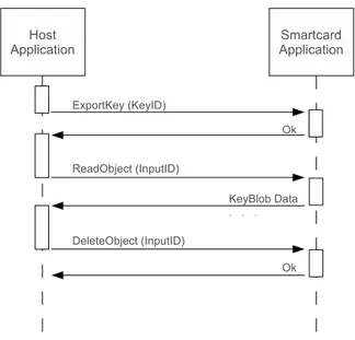
To overcame the limitation of the protocol T=0, because of the fact that the Le field in the APDU optional body is one byte length, every time that an application needs to transmit to the card or the card wants to transmit to the host more than 256 bytes of data, we need to perform more times the same operation. To overcome this limitation, we can store the content of the following APDU dealing with a object, by a means of an incremental offset or, viceversa, using this to read the content of the object split in multiple of Le bytes. With operations dealing with keys two temporary objects have been introduced. Input and output objects. For example, to import a key into the card, the key data must be supplied into the input object and the ImportKey command read from this, with the purpose of restoring the keys. Analogous, the Exportkey command, calculates the key data and put it into the output object. Data can be retrieved with a set of reads, as is shown in figure 3.1.
Some commands have the opportunity to specify if they need the I/O objects or if the APDU buffer is enough for their necessity. The data location byte, is furnished by the application to specify if the data size is small enough to fit in an APDU or if the operation needs to involve the I/O object. In ComputeCrypt a 1024 bit RSA keys, generates cryptograms of 128 bytes length at time and for this purpose APDU buffer is suffice. Setting properly this byte we can manage more larger cryptograms for instance. As we can image, the I/O objects can contain sensitive information, and every effort must be done to preserve their safety. Every operation that involves I/O objects performs at least three method calls. One for create the object, the operation self, and a call to delete the object. If an error occur during the execution of one the last two operations, the object could has not been deleted and it retains its content. To avoid these situations the protocol requires that the temporary object must be deleted as soon as possible and at every card reset. The security of composite operation is both granted by the operative system that acquires the mutual exclusion (the application needs to acquire an exclusive access to the smart card reader) of the resources involved in the operation, and by the I/O object deletion at every card reset (to avoids attacks).
3.3
Security model and access control enforcement
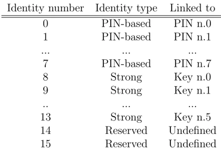
The MUSCLE card access control list model allows the execution of operations only after proper authentication. The authentication can be performed by means of PINs code verification, a challenge-response cryptographic protocol or a combination of previously two. Access to on-card resources is ruled by the means of the authentica-tion needed to access both keys and objects. The protocol achieves the authenticaauthentica-tion introducing the concept of identity. At every identity is associated one of the sev-eral authentication mechanisms that applications have to use in order to unlock the wished operation. The identities n.0-7 are also known as PIN-based, the n.8-13 are also known as strong and they are associated with cryptographic key n.0-5 and 14-15 are reserved.
Identity number Identity type Linked to 0 PIN-based PIN n.0 1 PIN-based PIN n.1 ... ... ... 7 PIN-based PIN n.7 8 Strong Key n.0 9 Strong Key n.1 .. ... ... 13 Strong Key n.5 14 Reserved Undefined 15 Reserved Undefined
Table 3.1: Association between identify, PIN and cryptographic key numbers
The successful run of one of these mechanisms of authentication cause the state of log in of the corresponding identity and the increasing of the current level of logged in identities. In this way an application can gradually gain higher security level that grant access to more card capabilities. The LogOutAll command causes to return back to unauthenticated state. In this way, applications will able to use operations both keys and objects only if the current level of logged identities satisfy the level request by the operation self. As before mentioned, operations on objects are write, read and delete. Keys operations are import (write), export (read) and use. Every
operation is linked with an access control word, a 16 bits word that, depending on its configuration takes on different meanings. Particularly an all-zero ACW has the meaning of operation publicly available, an ACW with some bits set means that the corresponding identities must be logged in to perform the operation and, all in all, an all-ones ACW has the meaning of operation never available, this is useful, for instance to disable the reading of a private key. The following table summarizes the concept:
Binary ACW Meaning
0000 0000 0000 0000 Operation always allowed
0000 0000 0000 0010 Operation allowed only if PIN n.1 has been verified 0000 0001 0000 0010 Operation allowed only if PIN n.1 and E
External authentication using key n.0 has been verified 0000 0000 0000 0000 Operation never allowed
Table 3.2: Some ACWs and their meanings
This model allows at least four levels of protection for card services and these are: operation always allowed if the ACW not requires authentication, PIN protected if the ACL requires that one of the seven PINs has been verified, strongly protected if the ACW requires strong authentication mechanism, and disabled if the ACW is all-ones, forbidding its execution.
3.4
PIN management
APDUs have been defined to manage PINs and their creation, verify, changing and unblocking. Several PINs could exist on a card. A special PIN, the transport PIN n.0, would already exist after that the applet has been instantiated on card to prevent allocation of card resources without the user knowledge.
3.5
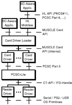
Host-side architecture
The bottom layers of the architecture, as shown in figure 3.2, consists of PCSC-lite daemon that manages the SC-related hardware of the PC like readers for instance.
Readers are supported by a means of a drivers, many of which are open source, imple-menting either the IFD-Handler or CT-API interface. Card-independence is achieved by the use of common API. Particularly, the Card Driver Loader is responsible to load the correct driver of the card by means of the address to response, ATR. The MUSCLE card API gives a way to access to the services supported by the applet on the card, like data storage and cryptographic services. On top of the architecture fur-ther applications has been developed. An open source PKCS-11 module that map the functions that has been defined into the standard in a sequences of MUSCLE Card API calls. A module called PAM has also been developed. This allows authentication based on smart card in Unix-like system.
3.5.1
API function set
The MUSCLE Card API could be grouped together in the following three sets:
Session management
This set consists of the all calls needed to enumerate readers, manage tokens, estab-lish and release connections. Specifically, ListTokens enumerates readers connected to the system either if a token was inserted or not, and lists all supported card devices in the system. WaitForTokenEvent allows applications to wait until a to-ken has been inserted and notifies also the event of card removal. Once the card is into the reader a call to the EstablishConnection allows to connect to the card in either exclusive or in shared access. If exclusive access is needed the lock can be ob-tained with a call to BeginTransaction and released with EndTransaction function. ReleaseConnection function allows to reset the device.
Data storage service
For data storage features, the framework introduces the concept of object as a simple container that can be used to store data independently by their nature. Every object is identified by means of a 32-bits object identifier (OID). Access control to data storage service is per-object and per-operation based (create, read, write, delete). Specifically, CreateObject allows the creation of an object onto the card. Users or applications have to furnish an OID for the object and an access control list. This information could be retrieved invoking the ListObject method. Reading and writing of the pre-created objects can be performed with, respectively, the methods ReadObject and WriteObject. There is not any hierarchy of the objects. Applications are able to create objects until memory is available, ignoring totally all about the memory management strategies of the smart card. The API does not defines specif object content also, leaving the applications completely free to store their data. So the object content is strictly linked with the application itself. In spite of many smart card device tends to separate between a public and private space memory, MUSCLE card approach has an unique vision of the memory space. Sensitive information into object are protected with an per-operations ACW, customized during the creation of the object.
Cryptography services
The API allows to generate, import, export and use keys. Keys are these supported by the API Java Card 2.1.x. ListKeys apart, every other operation on a key is allowed after only properer authentication. On-board key generation is allowed and it is guaranteed that the private on-board generated key can never be export toward the outside. Access control is per-operations based.
3.6
MUSCLE card PCSC Lite API
The API gives to the developers of applications a means to access the PC/SC on-card Resource Manager in a simple way. The API tries to abstract the complexity of the low-level programming providing high-level API that allow homogeneous access of cards and readers among different vendors. Those API emulates the winscard API used on Commercial platform. The API furnishes a means to open/close com-munications with the Resource Manager, obtains a list of connected IFDs and their capabilities, opens a connection with one of they in a exclusive or shared mode, lists available ICCs, sends APDU commands to a ICC, reset ICC and etc.
3.7
MUSCLE card PCSC IFD Driver API
The API allows to design a driver for a device PC/SC compliant and, hence, supported by the MUSCLE PC/SC Resource Manager. This interface is designed to fit the needs of every smart card like device. The API gives a way to open/close a communication channel with an IFD, lists its capabilities, enables to manage electrical signals and etc.
3.8
CT API
Writing a compliant CT IFD driver means write a driver that works with PCSC Linux Smart Card Resource Manager. To write the driver we have to implement
three basically functions: CT init().
CT data(). CT close().
The first allows to establish a connection with a IFD. The second parameter of this function is a port number. Given this, the appropriate call can be performed in order to establish a connection with the port. For a serial connection to the PORT COM2 the CT init invokes IO InitializePort(9600,8,’E’,"/dev/ttyS1");. The sec-ond, the CT data, is responsible to open a communications channel with the IFD, to send outgoing or receive incoming APDU commands to/from card. Destination can be picked by DAD (destination address). If its values is zero, the outgoing command is intended for the ICC, if one for the IFD. Finally, the CT close closes the connection to the port. It takes as parameter the number of terminal. CTBCS, Card Terminal -Basic Command Set allows to send a set of constant commands CT compliant, mak-ing possible the execution of the same command across multiple vendors. Commands set consist of:
Request ICC, class = 0x20, ins = 0x12, asks to the IFD to wait for a indicated time interval the ”card inserted” event. The command is blocking unless the time interval indicated is zero.
Eject ICC, class = 0x20, ins = 0x15, assumes the IFD is on. Turn it off. Get Status, class = 0x20, ins = 0x13. It is intended for card power and card
in/out status. The returned byte assumes the following means: – 0 means not inserted card
– 3 means cart inserted but not powered – 5 means cart inserted and powered
PCSC
4.1
Introduction
Smart cards are secure computing platform designed to work in an unsafe and un-trustworthy general purpose computing environment like a personal computer. They are capable to store in a secure way critical and sensitive information like private keys, account numbers, password and so on. At the same time they supply a way to process the information previously mentioned, without expose these at common risks of a PC, like virus, trojan horses etc. This become very important every time we are involved in operations like generation of keys, network authentication based on digital certificate and so on. So, for the motivations before discussed, the widely use of smart cards is mandatory in all these environments in which the needs of security plays a key role. Until now, the main hamper to the spread of this technology, has been the lack of interoperability at several levels, that can be summarized as:
1 - The lack of standards to interface PCs and smart card readers. This complicate the creation of applications that works with smart card readers across a variety of vendors.
2 - The lack of high-level interfaces make difficult the development of applications. The purpose of the proposed architecture is to allow interoperability among com-pliant PCSC devices provided by a variety of vendors.
4.2
Architecture overview
A brief description of the architecture follows.
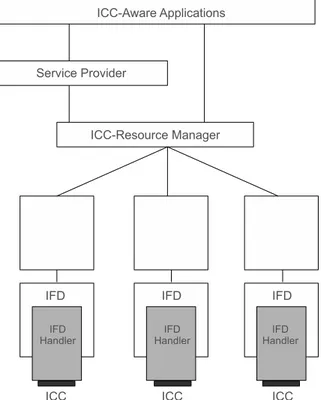
Figure 4.1: General architecture
4.2.1
ICC
Integrated Circuit Card, more common known as smart card, is a credit-card size plastic case with embedded a microprocessor chip. Smart card compliant with the standard PCSC must be conform both electrically and physically to the IS07816 part 1, 2,3 standard. An ICC is a computing platform designed to support services like secure data storage, complex cryptographic services etc.
4.2.2
IFD
Interface Device, more common known as smart card reader, is the physically interface through the PC communicate with the smart card. It is responsible to supply power
DC, clock signal, I/O line to the smart card. Reader of smart card compliant with the standard PCSC must be conform both electrically and physically to the IS07816 part 1, 2,3 standard. It is the responsibility of the IFD the mapping between the ADPUs of application and the corresponding ICC command.
4.2.3
IFD-Handler
The IFD-Handler allows a map between the native capabilities of the IFD, supplied by its driver, and the PCSC IFD interface. It is typically a low-level software running into the PC that supports I/O channel and much. The IFD-Handler enables the interoperability among different vendors of IFD.
4.2.4
ICC resource manager
The ICC is a key component of the architecture. It is a system level component and must be provided by the operating system vendor. It is responsible for managing the access control to IFD and, across them, to the ICC. More specifically, it is responsible for:
1 - Identification and tracking of resources. These includes:
Tracking of available IFD and make it accessible to the applications. Tracking known ICC types, and make it accessible to the applications. Tracking the events of insertion and removal of ICC and maintain
infor-mation about available ICCs within IFD.
2 - It is responsible to manage the allocation of resource of IFDs across multiple applications and connections with the IFDs in either a shared or exclusive mode.
3 - Support of transaction on the access to available services within an ICC. Trans-actions allow multiple command execution without interruption, ensuring data consistency.
4.2.5
Service Providers
The Service Provider is responsible to make accessible the functionality-relevant of a ICC or IFD through high-level programming interfaces. This API can be used as released or can be enhanced to meet the needs of a specific application domains.
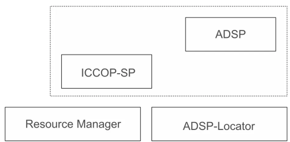
ICC Service Provider
An ICC Service Provider is a Service Provider that interfaces ICC functionality. Essentially we have three different kinds of ICCSP:
1 - ICC Operating System SP - ICCOSSP interfaces functionality from a specif ICC Operating System. It is responsibility of the card vendor.
2 - Application Domain SP - ADSP, Service Provider that interfaces an particular on-card applications. It is responsibility of the application developer.
The ICCOSSP grants the access to a specific functionality of a ICC through high-level API. The specification of PCSC defines interfaces for common file access and for authentication services. The vendors of ICC that implements these services, should use the interfaces previously defined. Additionally interfaces can be introduced to meet the requirements of specific domains. ADSP is designed to interface with the applications on-card and it is totally system-independent. This allows applications developers to write his application regardless to a specific ICC or IFD. ADSP uses a dynamic assignment mechanism through an ADSP Locator which allows the dynam-ically assignment of an ADSP.
ADSP Locator
ADSP Locator is itself a service provider, typically supplied by the ICC issuer, that is loaded by the Resource Manager in order to give to an off-card application a way to list on-card applications and a way to retrieve a reference to the ADPS of an specific on-card application.
Figure 4.2: Service Providers
Card Recognition System
Typically, ICC are identified by means of the ATR String. The card recognition system based on the parse of the ATR is limited because of the restricted length and complexity of this string. In a more complex card recognition system, all the information regarding the ICC must be available on the ICC itself, stored in a ICC Info Structure (like an ”Extended ATR”), that could be a file or an applet burned in ROM. Specifying a command in the historical bytes, the Resource Manager has a way to retrieve the information contained in this structure and the information retrieved help the Resource Manager to identify the ICC itself. So, when a ICC is inserted, the Resource Manager retrieve (recover) the info, get the ADSPL reference from the ICC info structure and load the ADSPL. A list of on-card applications could be retrieved and sent back to the off-card applications, that can choose the appropriate on-card application and load the correct ADSP to interact with the on-card application.
Cryptographic Service Provider - CSP
A cryptographic service provider is implemented like an ADSP for an ICC that include a card recognition system. The interfaces defined in this specification are those needed to:
Manage keys. Digital signatures. Hashing.
Bulk encryption system. import/export keys.
4.2.6
ICC-aware application
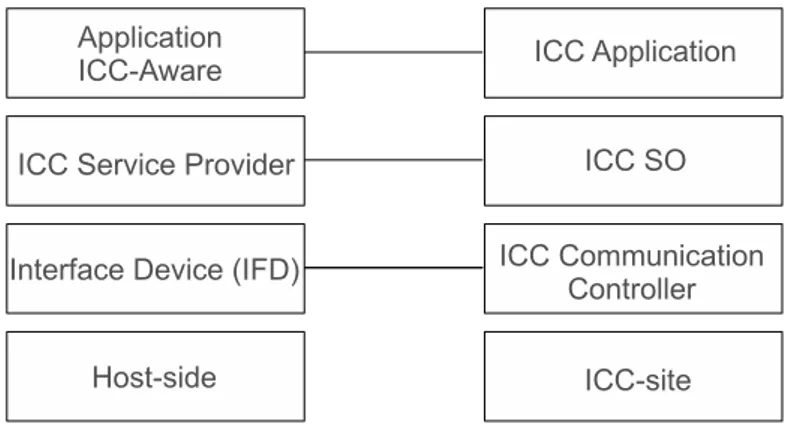
Applications ICC-aware are host-side programs that want to utilize the functionality provided by ICCs. The specification of PCSC offers a mechanism to map the request of an host-side application to the ICC, which is, typically, a single user/threaded application, working on a multiple application environment. A peer-to-peer represen-tation of the architecture is shown in figure 4.3
Java Card Emulator
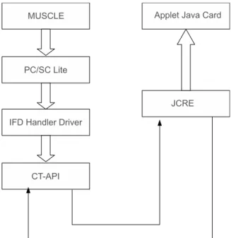
Java Card Emulator, is a well-integrated solution that allows application developer to test every single aspect of their applets. The emulator allows to recreate exactly an operative environment in which smart cards and readers are emulated by a PC environment. A third component, a Java stand alone application emulate the Java Card installer and the on-card applet loading. The architecture of the emulator is shown in figure 5.1
Figure 5.1: Java Card Simulator architecture
As we can see, the emulated host-side of the architecture, consists of an low-level driver implementation by means of CT-API and of MUSCLE card API at the bottom of the architecture. The emulated host-side is PCSC-lite transparent. The emulated card-side consists of a JCRE, developed from JRE, and of a smart card. The emulated Java Card allows the serialization and deserialization of the objects in order to support the storage services of a real smart card, preserve the content of the memory of the emulated smart card when the power supply goes off (equivalent to switch off the application).
5.1
Implementation details
Follows a brief description of the design of the emulator.
5.1.1
JCRE
To emulate the JCRE, Java Card Emulator uses Java VM, the microprocessor and the memory space of the workstation in which it is executed. The communication between the reader and the card is asynchronous by means of the methods signal and wait. When the event ”card inserted and powered” occurs, a new thread JCManager, entry class for the emulated JCRE, is created. The main body of the class consists of an infinite while loop. The thread is blocked waiting for an APDU to compute (the thread is a suspended state). When this event occurs, the thread is awakened, the C-APDU processed (the method process of the applet is invoked), and a R-APDU is sent back in order to awake the thread that was waiting for the answer. The serialization of the class allows to maintain the value of ”persistent (serialized) objects” across multiple switches off/on of the JVM, that simulate somehow the persistence of the memory across multiple CAD sessions.
5.1.2
CAD
The class that simulate the CAD is JCREader. The main body of this class, initialized its status to WAITING INIT, open a socket for the port 4000 and start executing an
infinite loop in which:
1 - It performs the reading of the opcode into the frame.
2 - It examines the first byte of the command field. The command can be intend for the reader, in this case it computes the command. If the command is an C-APDU it invokes an internal method to submit the C-APDU to the applet.
3 - In both cases a response frame is packed and sent back.
4 - The loop ends and begins again.
The CAD is implemented as a state machine in which the states are WAITING INIT and WAITING DATA. If the CAD is in WAITING INIT state, it is wating for an initial-ization frame (INIT OP) and, when received, the method CT init is invoked allowing to establish a client-server connection with the reader. Completed the CT intit the status of the server is updated to WAITING DATA. In the WAITING DATA state, when a frame is received, the CAD examines the first byte, the CLA byte of the command field. If this is 0x20 a CT-BCS command has been received and the INS field allows to distinguish between RESET, REQUEST ICC, Get Status and EJECT ICC; otherwise, if the CLA is not 0x20, then an C-APDU has been received. In this case, the CAD instantiates a C-APDU object and invokes the internal internalSendAPDU method to allow the execution of the intended command. The response frame will contain the R-APDU.
The CAD includes a GUI, developed with the javax.swing package. The GUI allows the user to simulate four different states in which the card could be.
1 - Card not inserted.
2 - Card inserted but cannot determinate if it is powered or less.
3 - Card inserted but not powered.
Figure 5.2: States of the server
The GUI gives users the possibility to select one of the four states previously mentioned with a four radio buttons and, at every button is associated the equivalent state.
Figure 5.3: CAD Gui
5.1.3
ClassLoader and JCManager
Every moment a smart card, in the emulator context, is described by means of two files: