1
POLITECNICO DI MILANO
SCHOOL OF INDUSTRIAL AND INFORMATION ENGINEERING
MASTER OF SCIENCE IN MECHANICAL ENGINEERING MECHATRONICS AND ROBOTICS
AUTOMATIC MOTION PLANNING OF
REDUNDANT DOUBLE-ARMED COLLABORATIVE
ROBOTS FOR BIN PICKING APPLICATIONS
Candidate:
Emiliano Staniscia Supervisor:
Prof. Hermes Giberti Company supervisor:
3
Abstract
The aim of this thesis is the development of a software for collaborative redundant multi-armed robot’s automatic trajectory planning.
Automatic trajectory planning is one of the most interesting research branches in the robotic field. In the last years various research groups have published tons of papers describing alternative methods to face the problem of modelling complex robot kinematics and environments, managing properly their interactions and the necessity of finding in a fast and computationally-efficient way a safe, free-of-collisions trajectory for the robot. Some of the most relevant examples of path planning algorithms and techniques developed in the last decades are the RRT family of planners and the SBL one.
In most of the industrial implementations, vision systems are the best way to provide to these algorithms informations about the environment and the targets that the robot have to reach. Of course, automatic motion planning techniques have some typical implementation problems. For these reasons, their usage in the contemporary industrial sector is limited to few practical applications. One of the most important is of course the bin picking one. Industrial robots guided by vision-based devices are already extensively used to pick randomly-oriented objects from a bin, but the typical final aim of this technology has always been the feeding of an other machine, belt or palettizer.
The main novelty of this thesis is in the development of trajectory planning methodologies for of a relatively new type of industrial manipulator: the collaborative, redundant, double-armed ABB Yumi robot, specially designed to mimic human capabilities. Yumi has the potentialities to extend the basic bin picking operation, already performed by standard industrial robots, to new industrial contexts such as the assembling or the human co-operation ones. This robot is already used for picking co-operations, but it’s always needed to organize its working area and programming its movements a priori. Combining vision systems and automatic motion planning features with Yumi capabilities, it’s possible to fully automize small objects assembly operations without designing rigid and expensive feeding systems, but with the flexibility and simplicity of a bin picking procedure.
The developed software solves some intrinsic problems related to the use of the Yumi robot in this type of applications. First of all, the necessity of managing its complex, redundant kinematic structure. Secondary and most important, the problem that standard automatic planning algorithms are not studied to interact with this type of robot. The coordination of its two arms, in fact, is of fundamental importance in order to guarantee a high productivity of the future applications, but automatic planners are typically not capable to manage more than one moving entity.
The thesis presents different approaches, developed in the last years, for the resolution of this kind of problem and proposes a method capable of bypassing it.
4
The software is based on one of the most efficient, well-organized and reliable open-source libraries for robot programming free available on the web: Klamp’t. Its capabilities of managing redundant, multi-armed kinematic structures have been explored and a smart procedure for double-armed coordinated bin picking applications, based on its functionalities, has been developed.
The thesis has been developed in collaboration with the ISS company, in which most of the programming and experimental works were done. ISS is a Politecnico spin-off and one of the main Italian company in the development of robot guidance systems based on vision devices with applications in the bin picking field.
The thesis has the following structure:
• Chapter 1 is a short introduction to the industrial context and the possible reasons for the developing of this work;
• Chapter 2 introduces the current state of art about vision systems and motion planning algorithms and technologies;
• Chapter 3 is a brief explanation of the main concepts regarding robot kinematics; • Chapter 4 presents the main motion planning algorithms and describes a procedure
useful to choose the most suitable algorithm for the final application;
• Chapter 5 describes the development of the software and the tests on the real application;
• Chapter 6 describes future improvement for the software.
5
Sommario
Lo scopo della tesi è lo sviluppo di un software per la pianificazione automatica di traiettoria per robot collaborativi, ridondanti a doppio braccio.
La pianificazione automatica di traiettoria è uno dei rami di ricerca di maggior interesse industriale nell’ambito della robotica. Negli ultimi anni vari gruppi di ricerca hanno prodotto grandi quantità di articoli scientifici, che descrivono soluzioni alternative per confrontarsi con il problema di modellare ambienti e complesse architetture robot, gestendo accuratamente la loro interazione e la necessità di trovare velocemente traiettorie prive di collisioni per il robot. Alcuni dei più importanti esempi di algoritmi per la pianificazione automatica di traiettoria sviluppati negli ultimi decenni sono la famiglia degli algoritmi RRT e l’algoritmo SBL.
Nella maggior parte delle applicazioni industriali, i sistemi di visione sono il modo migliore di fornire a questi algoritmi le informazioni riguardo l’ambiente e l’obiettivo da raggiungere. Ovviamente le tecniche per la pianificazione automatica di traiettoria hanno alcuni tipici problemi di implementazione. Per queste ragioni, il loro impiego nell’attuale panorama industriale è limitato a poche applicazioni pratiche. Una delle più importanti è di certo quella della presa da cassone. I robot industriali, guidati da sistemi di visione, sono già frequentemente utilizzati per prelevare oggetti disposti casualmente in un cassone, ma tipicamente lo scopo finale di questa tecnologia è sempre stato quello di rifornire altre macchine, nastri trasportatori o pallettizzatori.
La principale novità di questa tesi risiede nello sviluppo di metodologie di pianificazione di traiettoria per una tipologia di robot relativamente nuova: il robot collaborativo, ridondante, doppio-braccio ABB Yumi, progettato specificatamente per emulare le capacità cinematiche umane. Yumi ha le potenzialità per estendere l’operazione di presa da cassone standard, già realizzata da robot tradizionali, a nuovi contesti industriali come quelli dell’assemblaggio e della cooperazione uomo-robot. Questo robot è già utilizzato per operazioni di presa, ma è necessario organizzarne metodicamente l’area di lavoro e programmarne in anticipo i movimenti. Combinando le caratteristiche dei sistemi di visione e della pianificazione automatica di traiettoria con le capacità di Yumi, è possibile automatizzare le operazioni di assemblaggio di piccoli oggetti, senza la necessità di progettare rigidi sistemi di movimentazione, ma con la semplicità e flessibilità di un’operazione di presa da cassa. Il software sviluppato risolve alcuni problemi intrinseci collegati all’uso del robot Yumi in questo tipo di applicazioni. Prima di tutto la necessità di gestire la complessa struttura cinematica ridondante. Inoltre, il problema che gli algoritmi di pianificazione automatica di traiettoria standard non sono studiati per gestire più di un’entità in movimento. La tesi presenta differenti approcci, sviluppati negli anni, per la soluzione di questo tipo di problematica e ne propone uno capace di aggirarla efficacemente.
6
Il software si basa su una delle più affidabili, efficienti e meglio organizzate librerie open-source per la programmazione robot disponibili in rete: Klamp’t. È stata studiata la sua capacità di gestire strutture cinematiche ridondanti e multi-braccio ed è stata sviluppata una procedura per applicazioni di prese da cassone a due braccia coordinate, basata sulle sue funzionalità.
La tesi è stata svolta in collaborazione con l’azienda ISS, presso la quale sono state svolte molte delle attività di programmazione e sperimentali. ISS è uno spin-off del Politecnico e una delle maggiori aziende italiane nello sviluppo di sistemi di guida robot con applicazioni nel campo della presa da cassone.
• Il capitolo 1 è una breve introduzione al contest industrial e alle possibili motivazioni per lo sviluppo di questo lavoro di tesi;
• Il capitolo 2 introduce all’attuale stato dell’arte per i sistemi di visione e le tecniche di pianificazione del moto;
• Il capitolo 3 è una breve descrizione dei principali concetti riguardanti la cinematica dei robot;
• Il capitolo 4 presenta i più importanti algoritmi di pianificazione del moto e descrive una procedura utilizzata per la scelta del codice più adatto all’applicazione finale; • Il capitolo 5 descrive il software sviluppato ed i test sull’applicazione finale; • Il capitolo 6 descrive I possibili futuri miglioramenti al software.
7
C
ONTENTS
List of Figures ... 10
1 Introduction ... 14
1.1 The Industrial Scenario ... 14
1.2 Aim Of The Thesis ... 18
2 The state of art ... 23
2.1 Introduction to Vision Sensors ... 23
2.2 Introduction to motion planning ... 25
3 Robot kinematics ... 32
3.1 static and kinematic of industrial robots... 32
3.2 statics of the rigid body and kinematic chains ... 35
3.3 inverse kinematics for redundant manipulators ... 39
3.4 input files ... 42
4 Motion planning algorithms ... 47
4.1 configuration space ... 47
4.2 general planning formulation ... 50
4.3 rrt and sbl algorithms ... 53
4.4 choice of the planner ... 61
4.4.1 RRT planner ... 64
4.4.2 BiRRT planner ... 66
4.4.3 SBL planner ... 68
4.4.4 Overall evaluation ... 70
5 The developed software ... 72
5.1 structure of the application ... 72
5.1.1 The scanning phase: ... 74
5.1.2 The pattern matching and pose computation ... 75
5.1.3 The planning code: ... 77
5.1.4 The Yumi Program ... 89
5.2 the final version of the software ... 96
5.2.1 The theoretical background ... 97
5.2.2 Proposed solutions ... 99
8
10
L
IST OF
F
IGURES
Figure 1: a robot working area ... 14
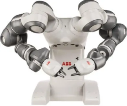
Figure 2: Yumi robot ... 16
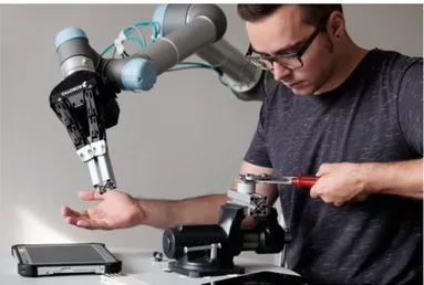
Figure 3: example of HRC ... 19
Figure 4: ISS logo ... 20
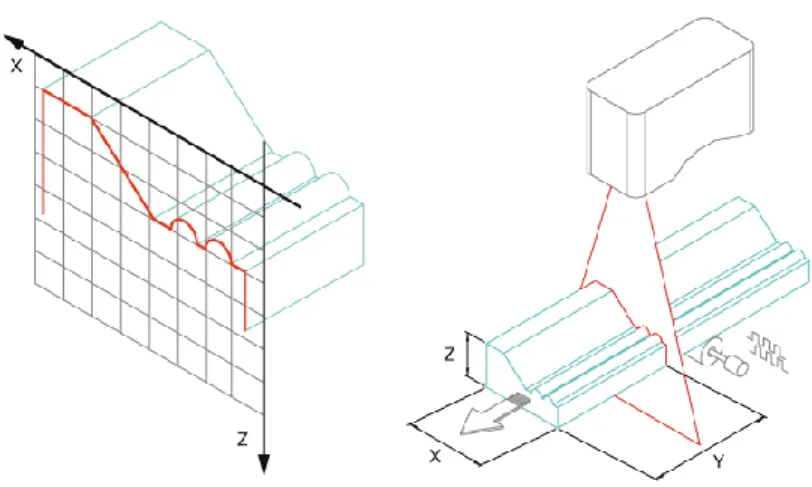
Figure 5: laser scanner ... 24
Figure 6: single joint motion planning ... 26
Figure 7: over-fly ... 28
Figure 8: piano-mover problem ... 29
Figure 9: the C-space ... 29
Figure 10: RRT mapping ... 30
Figure 11: an open kinematic chain ... 33
Figure 12: Newton-Rhapson algorithm ... 34
Figure 13: 3D object relative position ... 35
Figure 14: frame rotations ... 36
Figure 15: 3D kinematic chain ... 38
Figure 16: D-H parameters ... 38
Figure 17: human arm kinematics ... 40
Figure 18: Yumi's arm ... 40
Figure 19: non-convex shape ... 42
Figure 20: stl mesh ... 43
Figure 21: .ROB file ... 44
Figure 22: .XML file ... 45
Figure 23: xml visualization ... 45
Figure 24: kinematic duality ... 47
Figure 25: homeomorphic transformation... 48
Figure 26: examples of manifold ... 49
Figure 27: general planning problem ... 50
Figure 28: Voronoi diagram ... 51
Figure 29: RRT expansion ... 54
Figure 30: RRT main ... 55
Figure 31: RRT expansion logic ... 55
Figure 32: RRT connection logic ... 56
Figure 33: RRT collision checking ... 56
Figure 34: trap obstacle ... 57
Figure 35: BiRRT main ... 57
Figure 36: BiRRT behaviour ... 58
Figure 37: SBL main ... 59
Figure 38: SBL expansion logic ... 59
Figure 39: SBL connection logic ... 59
Figure 40: SBL segment check ... 60
Figure 41: SBL path check ... 60
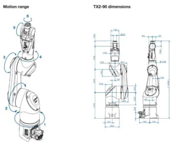
Figure 42: TX2 90 layout ... 61
11
Figure 44: configuration of the test ... 62
Figure 45: positioning of the target ... 63
Figure 46: RRT percentage of success ... 64
Figure 47: RRT mean number of iterations ... 65
Figure 48: RRT mean planning time [s]... 65
Figure 49: RRT mean path length [m] ... 66
Figure 50: BiRRT percentage of success ... 66
Figure 51: BiRRT mean number of iterations ... 67
Figure 52: BiRRT mean planning time [s] ... 67
Figure 53: BiRRT mean path length [m] ... 68
Figure 54: SBL percentage of success ... 68
Figure 55: SBL mean number of iterations ... 69
Figure 56: percentage of success vs number of iterations ... 69
Figure 57: SBL mean planning time [s] ... 70
Figure 58: SBL mean path length [m] ... 70
Figure 59: percentage of success comparison ... 71
Figure 60: mean planning time comparison ... 71
Figure 61: layout of the test case ... 72
Figure 62: 3Dcps fast ... 74
Figure 63: the workpiece ... 74
Figure 64: points cloud... 75
Figure 65: Halcon script part 1 ... 76
Figure 66: Halcon script part 2 ... 76
Figure 67: Halcon script part 3 ... 76
Figure 68: Halcon script part 4 ... 77
Figure 69: planner part 1 (scene generation) ... 78
Figure 70: planner part 2 (grasp points definition) ... 79
Figure 71: grasp points ... 80
Figure 72: planner part 3 (priorization procedure) ... 80
Figure 73: planner part 4 (inverse kinematics and collision checking) ... 81
Figure 74: planner part 5 (approach and depart points definition) ... 82
Figure 75: bin picking sequence ... 83
Figure 76: planner part 6 (planning procedure) ... 84
Figure 77: planner part 7 (linear path computation) ... 85
Figure 78: trajectory visualization ... 85
Figure 79: planner part 8 (trajectory re-writing) ... 87
Figure 80: example of string ... 87
Figure 81: planner part 9 (communication protocol) ... 88
Figure 82: Yumi frontal ROI ... 89
Figure 83: Yumi lateral ROI ... 89
Figure 84: Yumi gripper... 90
Figure 85: Rapid main communication protocol (part 1) ... 91
Figure 86: Rapid communication protocol (part 2) ... 92
Figure 87: Rapid motion main protocol ... 93
Figure 88: Rapid "init" procedure ... 93
12
Figure 90: Rapid "TesiCycle" procedure ... 95
Figure 91: some images of the experimental tests ... 95
Figure 92: super-graph composition ... 97
Figure 93: Planner v2 (strategy selection)... 99
Figure 94: updating visualization ... 100
14
1
I
NTRODUCTION
1.1
T
HEI
NDUSTRIALS
CENARIOIn the last few years, a new industrial revolution, named “Industry 4.0”, has begun. One of the main ideas behind this new approach to the world of industry and manufacturing is the flexibility of the production system. In the industrial field, the necessity of having machines able to adapt their behaviour to different products, tasks and requirements is becoming more and more important, in order to ensure the maximum productivity and allow fast and smart production systems reconfigurations.
This evolution of the production system is achievable only with a strong automatization of the production process. In this context, one of the most important roles is played by industrial robots. A robot is a reprogrammable, multifunctional manipulator designed to move materials, parts, tools or specialized devices through various programmed motions for the performance of a variety of tasks.
But robots are not a new technology. They are diffused in production plants all around the world since 60’s. In these years their use has been always affected by an intrinsic rigidity due to the necessity of programming them to reach points in the workspace that must be defined a priori. The robot in fact is not able to “see” the environment, so all trajectories, needed to perform a task must be already known during the programming phase in order to correctly avoid obstacles and grasp objects. This requirement involves the necessity to configure the entire working area of the robot in order to feed pieces in specific positions and orientation; In this way they can be correctly manipulated by the robot. For this reason, are often required complex and expensive machines such us conveyor belts, palletizers, shakers or rotary tables.
15
The main problem is that, if, for any reason, the production changes, also the entire sequence of machines used to feed the robot may be, at least partially, changed, with additional costs due to idle and configuration time.
In a modern production plant, this type of approach to the design of a robotic cell is no more efficient from an economic and logistic point of view. The idea that is growing fast in the last years is trying to give to the robot information about the surrounding environment and decide at each working cycle how to behave. In this way may be possible to develop algorithms able to “choose” and provide to the robot trajectories based on the current position of workpieces. The main advantage is that the position and orientation of the objects to be grasped can be not pre-defined, allowing a strong simplification of the working cell and a reduction of costs.
The most important technology developed according with this idea is the vision servoing. Artificial vision devices are capable to mimic the human sense of sight and allow to gather information from the environment without contact. Applications of vision devices are very different and already diffused in a lot of industrial fields. Is possible to use this type of sensors for line-following applications tasks (such us welding or contouring applications), or for real time feedback in order to improve position control of the end effector. But nowadays the main use of vision in industrial robotics is to detect objects in the robot scene, whose position and orientation is then used for online path planning in order to drive the robot to the identified object. This type of application is typically called “Bin Picking”, because the most common work-area configuration is made of the robot, a bin in which workpieces are randomly posed and a structure to support the vision device, typically integrated in the cell used to delimit the workspace of the robot. As is possible to understand, with vision sensors, the cell configuration becomes very simple respect to a standard one, dedicated to standard programmed robot. That’s because is now possible to let the robot works, without knowing a priori how workpieces are exactly posed.
This type of approach to the problem of object’s grasping and manipulation trough robots, has of course a lot of advantages, but is affected by several difficulties in the implementation. First of all, there are a lot of issues related to sensor calibration, that must be faced in order to obtain a correct image acquisition in different environments affected, for example, by different light conditions. After the acquisition, is of fundamental importance to elaborate the image in order to reconstruct the geometry of the object that must be recognized. The reconstruction can be either 2D or 3D depending on the application and on the task’s necessity. The reconstruction is based on complex algorithms of pattern matching able to verify that the fundamental features of the image acquired (such us lines, vertex or faces) have a correspondence with the ideal model of the object that should be provided to the elaboration unit of the sensor. Once the object has been recognized is needed to estimate its pose respect to a reference frame, usually the robot’s one, that is a fundamental information for a correct trajectory planning. The planning phase requires other sets of algorithms capable of analizing the environment, typically provided by the user through CAD files, and generates a complete trajectory that must respect robot’s kinematic limits and must be free of collisions with the environment.
16
All these passages are expensive from a computational point of view and are made by a sequence of algorithms that run on a computer, typically integrated with the sensor and physically separated from the elaboration unit of the robot, that has only the final purpose of interpolating the trajectory already elaborated. For these reasons, companies operating in this field should, not only develop the vision device, but also all the post-processing sequence and the trajectory generation. The final product should be a guidance system able, with a correct tuning, to adapt its features to different robots and applications, reinforcing the concept of flexibility that is the main idea behind all the technologies described in this thesis.
The technologies just introduced are able to eliminate all the feeding architecture of a traditional robotic cell, but the traditional robot remains a separated entity in the production plant, that must be insulated in order to ensure safe working condition for human operators. These conditions are no more efficient in modern factories that require always more integration between men and machines. In fact, this is the only way to guarantee flexibility of the plant when different, complex products should be manipulated or assembled combining the high productivity of an automated system and the capability of realizing complex and various tasks of a human being. For this reason, in the last years, the main robot producers start to develop collaborative robots. Collaborative robots are intended to physically interact with humans in a shared workspace. This is in contrast with other robots, designed to operate autonomously or with limited guidance, which is what most industrial robots were up until the decade of the 2010s.
17
Cobots can have many roles: from autonomous robots capable of working together with humans in an office environment that can ask users for help, to industrial robots having their protective guards removed. Collaborative industrial robots are highly complex machines which are able to work hand in hand with human beings. The robots support and relieve the human operator in a conjoint workflow.
The tendence is to give to collaborative robots more freedom in movements respect to common anthropomorphous robots. For this reason, ABB has chosen to realize its first ever collaborative robot with a double-armed kinematics. Each arm is redundant (made of more than 6 joints), in order to give them movement capabilities comparable to the ones of a human being.
18
1.2
A
IMO
FT
HET
HESISThe technologies just introduced are already diffused worldwide. Collaborative robotics is considered as one of the nine main pillows of Industry 4.0. According to the SA Journal of Human Resource Management, “Industry 4.0 promotes technology innovation and human-robot collaboration (HRC). HRC on the manufacturing assembly line have been implemented in numerous advanced production environments worldwide. Cobots are increasingly being used as collaborators with humans in factory production and assembly environments” [1].
As already said, the idea behind the collaborative robotics is of giving the opportunity to a robot of realizing new tasks, mainly in collaboration with human workers. In this way, may be possible to combine the efficiency, repeatability and productivity of an automated system with the flexibility, capability to adapt to different situations and “sensibility” of human being. As reported in the paper “Human-Robot collaboration in industry”, from A. Vysocky and P. Novak, “The main goal of this innovative strategy is to build up an environment for safety collaboration between humans and robots. There is an area between manual manufacture and fully automated production where a human worker comes into contact with machines. […] Collaborative robotics establishes new opportunities in the cooperation between human and machines. Personnel shares the workspace with the robot where it helps with non-ergonomic, repetitive, uncomfortable or even dangerous operations” [2].
Is important to underline how, although many cobots, in particular Yumi, have human-like kinematic capabilities, they are not intended to fully substitute nor human workers neither actual technologies. The idea is of enlarging the portfolio of operations that a robotic system can realize, bringing some crucial advantages in the industrial field:
• From a socio-economic perspective, the deployment of robots produces higher competitiveness of companies in comparison with countries with very cheap labor. Even a small company can focus on costumer demands and offer a product for a lower price;
• Robot’s repeatable positioning accuracy and continuous operation provide better quality and lower requirements for post-processing and quality controls;
• Robots can speed up some operations and also adjust to special conditions, which can lead to the increase of productions;
• Limiting the uncomfortable, repetitive and tedious work results in lifting the burden from humans which can otherwise result in occupational disease. There is, in fact, a relation between the burden on laborers and the ergonomics of operations. Improving the working environment can lead to a decrease in the amount of occupational injuries.
Although robots are tough, fast and very accurate machines which can complete their tasks faster, with better quality and a lower price than humans, human factor remains important in some production systems. Some operations have to be adapted to actual conditions. Robots are not capable of thinking, they only execute commands, resulting in limitation of
19
these machines. Advantages are evident when robots replace laborers in non-ergonomic duties. As an example, we can mention the manipulation of heavy payloads, manipulation in uncomfortable positions, or tasks which are dangerous. Cobots may be also installed in monotonous operations which are uncomfortably repetitive.
One of the main examples of repetitive and uncomfortable task in all industrial plants is the bin picking operation.
Provide objects to a manufacturing or assembling system posing them in a bin, is easy and cheap and pick them from the bin may seem trivial for a human being. In practical this operation results heavy and repetitive and is often subjected to errors and loses of time when realized by a human labourer. For these reasons, in many industrial contexts, such as machines feeding, it has become a fully automatized operation, performed by industrial robots guided by various types of vision systems. The situation is different in the case of manual assembling operations of small objects. This type of tasks remains a prerogative of human beings due to the necessary sensibility and capability to adapt to different situations. The problem is that feeding of parts and storing of the finished component are repetitive, monotonous and uselessly tiring operations. If a collaborative robot, adequately equipped with a guidance system, would be able to autonomously pick randomly posed objects and help the labourer to manipulate them, working conditions may improve, increasing at the same time the productivity and precision of the procedures.
Starting from this idea, the necessity of developing codes able to plan automatic trajectories for these complex kinematic entities becomes crucial. Is in fact important to underline how standard automatic planners are not yet fully studied for managing redundant double-armed robots as the Yumi one, so is fundamental to understand how take advantage of Yumi’s capabilities in order to realize efficient and flexible bin picking operations easily integrable in HRC assembling tasks.
20
For these reasons, the aim of this thesis is of developing a program capable of integrating one of the most efficient and adaptive collaborative robots, the Yumi one, in bin picking operations, with the final future purpose of combining vision systems, automatic trajectory planning and collaborative robot technologies in co-operation tasks in the industrial context. The software will have the capabilities to elaborate informations coming from a vision system and use them to perform an innovative coordinated bin picking operation taking advantage of both arms of the Yumi.
One of the main Italian players in the bin picking field is the ISS – Innovative Security Solution srl. It is a Politecnico di Milano spin-off company which operates in the industrial automation sector and produces robot guidance systems based on 3D vision systems. ISS, moreover, actively cooperates with Politecnico, other Universities, applied research institutes and numerous companies in developing several research projects.
Figure 4: ISS logo
Since 2010 ISS has theorized the concept of “virtual tray” or, in other words, the idea of eliminating the palletizer, giving the robot the ability to directly grasp objects randomly posed on a physical tray.
Nowadays the company provides different sensors for various application, such us bin or belt picking, mainly based on two different vision technologies: laser triangulation and stereoscopic light pattern. These types of technologies currently represent the state of art for vision systems in industrial applications.
Although its leadership in the bin picking sector, it has never faced the problem of integrate collaborative robots in this type of applications. From this point of view, the Yumi robot is the most challenging example of collaborative robotics due to its double-armed redundant configuration. The standard commercialized ISS softwares are not studied to manage this type of robots. For this reason, the developed software is completely new and ISS knowledge has only helped to define, from a theoretical point of view, some preliminary routines and procedures that are commonly useful in any kind of automated picking applications. Also the final experimental set-up has been realized in the ISS company, that provides the vision system needed to generate input files for the software and a real Yumi
21
robot, in order to test the goodness of the developed algorithms also in terms of data transmission speed to the real system.
The software has been developed using the Klamp’t library. Klamp't stands for Kris' Locomotion and Manipulation Planning Toolbox. It is a cross-platform software package for modeling, simulating, planning, and optimization for complex robots, particularly for manipulation and locomotion tasks. It has been developed at Indiana University since 2009 primarily as a research platform and has been used in classrooms beginning in 2013. It has been used in several real-world projects, including the Amazon Picking Challenge, TeamHubo in the DARPA Robotics Challenge, and was the platform for the IROS 2016 Robot Grasping and Manipulation Challenge simulation track.
It provides various features in the fields of modelling and planning, including kinematic inversion algorithms for standard and redundant robots and many sampling-based motion planners.
Also other packages for robotic simulation and programming has been explored and tested. These are for example:
• ROS (Robot Operating System) is a middleware system designed for distributed control of physical robots, and Klamp't is designed to be interoperable with it. Various ROS software packages can replicate many of the functions of Klamp't when used together (Gazebo, KDE, Rviz, MoveIt!), but this approach is difficult since these tools are not as tightly integrated as they are in Klamp't. ROS is heavy-weight, has a steep learning curve especially for non-CS students, and is also not completely cross-platform (only Ubuntu is fully supported).
• OpenRAVE (Robotics and Animation Virtual Environment) is similar to Klamp't and was developed concurrently by a similar group at CMU. OpenRAVE has more sophisticated manipulation planning functionality. Does not support planning for legged robots, but simulation is possible with some effort. Simulation models are often conflated with planning models whereas in Klamp't they are fully decoupled. OpenRAVE is no longer actively supported.
• V-REP is a robot simulation package built off of the same class of rigid body simulations as Klamp't. It has more sophisticated sensor simulation capabilities, cleaner APIs, and nicer visualizations but is typically built for mobile robots and have limited functionality for modeling, planning, and optimization. It is also not created specifically for custom software development because it has its rigid and pre-defined user interface that cannot be easily re-implemented for real industrial applications. It is also not open-source, so its use for industrial purpose can become expensive.
It is currently implemented in two different programming languages: C++ and Python. Although most of the softwares developed by the ISS are written in C++, for the aim of the thesis, we have decided to write the software in Python, that has the important advantages to be easier in the configuration and to provide a lot of simple additional tools for simulation and visualization of the numerical results, but also for the generation of server-client connections for the implementation of experimental tests.
22 The thesis is organized as follows:
• Chapter 2 will introduce some basic concepts about the state of art in robot guidance systems, both from the vision and motion planning point of view. The first sub-chapter describes shortly the most important technologies in 3D object recognitions, then the most common concepts about both standard and automatic motion planning will be introduced;
• Chapter 3 will be useful to clarify most of the mathematical concepts behind a standard and redundant robotic system: differential kinematics, kinematic inversions and kinematic chains will be shortly described. In this way, the syntax of the input files, needed to model the structure of the Yumi robot, should result clearer and the reader should be familiar with most of the terms and functions presented in the last chapters;
• Chapter 4 presents three algorithms analysed in the preliminary phase of the thesis. They represent the alternatives for the core part of the developed software, responsible of the automatic planning procedure. These algorithms will be firstly described from a theoretical point of view, then applied on a simple simulation and the results will be studied and used to choose the planner for the final application; • Chapter 5 is divided in two parts: In the first part the development of the software will be presented, first in its basic version and then in the final version, capable of successfully use all the potentialities of the Yumi robot. all the relevant function of the algorithm needed to maximize its planning capabilities will be and its performances analysed in a simulated scenario in different input conditions. In the second part the experimental set-up will be described, underlying how the software can be easily integrated in a pseudo-real industrial bin picking task.
• The final chapter will be used for some considerations about the future final integration of the software in robot guidance systems for human-robot collaboration applications involving bin picking tasks.
23
2
T
HE STATE OF ART
2.1
I
NTRODUCTION TOV
ISIONS
ENSORSThis part of the thesis is intended to describe which are the main important technologies in the field of 3D metrology.
Nowadays there are a lot of methodologies for the automatic acquisition of an object shape: in the case of industrial field the main used and developed family of methods is the one of active optical systems.
An optical system is a technology that produces tridimensional informations from the combination of images, so the bidimensional projections of an object. These images should be acquired through one or more cameras. Advantages of these techniques are high execution velocity and no necessity of contact with the object to be measured. These features allow the extensions of this type of techniques to many industrial sectors affected by particular or dangerous conditions and environments.
Optical systems are divided in active and passive. Passive optical systems are based on image analysis and acquisition with no modifications of the light conditions by the user. In active optimal systems instead, the object to be measured is typically radiated by some specific light patterns.
This type of optical systems can be divided in other two families: active structured light optical systems and active non-structured light optical systems. The second type is made of all those acquisition methodologies in which some light source is used to improve the acquisition conditions. Some of these methodologies are retro-illumination and coaxial led illumination.
Structured light optical systems instead, have a different logic: the light source is a fundamental part of the acquisition process. For this reason, any type of image acquisition is characterized by a well determined light source.
One of the main technologies, which is part of this family, is active laser triangulation. In this methodology all geometric properties are estimated starting from the knowledge of the laser pattern. The most diffused approach is to use a laser plane. The intersection between the laser plane and the surface of the object to be measured, generates the so called profile, that has a deformed shape depending on the shape of the object. The reflected light is acquired by a camera. In order to perform the acquisition of an entire object is needed to create a relative movement between the laser source and the object. The movement can be a rotation or a roto-translation. The final acquisition will be the union of a lot of single profiles. The final device made of a moving light source and a camera is called laser scanner and is currently the main type of sensor developed by the ISS. Main advantages of this
24
methodology are a very good collimation of the light emission, the monocromaticity and the low power required.
Figure 5: laser scanner
One of the main problems is that this type of devices is characterized by a high inertia, due to the weight of the laser source, the camera and of the elaboration unit. For this reason, the acquisition velocity is not so high as other methods.
Another approach is the stereoscopic interferometry. It is based on the Moirè effect: the basic idea is to project a light pattern on the object and to acquire the image trough another light pattern rotated respect to the first one. These two patterns create a grid made of light and shadows areas that can be used to perform a 3D reconstruction. This method is extremely accurate and cheap, but is computationally heavy and does not work very well with objects characterized by sudden changes of depth, that cause too big deformations of the grid, or with objects that are too far from the camera, so is not typically used in big bin picking applications but only in tray picking. Another advantage is that it does not require a relative movement between the object and the measurement device, so the acquisition is typically faster respect to another methodologies.
For its features the stereoscopic interferometry is the most suitable technology for applications with collaborative robots and will be used for the experimental implementations of the algorithms developed during this thesis.
25
2.2
I
NTRODUCTION TO MOTION PLANNINGIn this part of the thesis the problem of trajectory planning will be introduced and discussed. First of all, will be presented the theoretical aspects of robotic manipulators trajectory planning. Then, will be introduced the current state of art methodologies in the field of automatic motion planning, that have of course important applications in industrial robotics, but, as it will be possible to understand, can be generalized to many problems and situations.
With the problem of “motion planning” in industrial robotics, is typically assigned the way the robot evolves from an initial posture to a final one. Motion planning is one of the essential problems in robotics and most of the success of a robot on the market depends on the quality of motion planning, that is typically demanded to the trajectory planner, one of the fundamental units of a robot controller. The result of the trajectory planning will be the reference input to the motion control system which ensures that the manipulator executes the planned trajectory. Planning consists of generating a sequence of values, attained by an interpolating function (typically a polynomial) of the desired trajectory. This interpolating function is usually called motion law and has to be designed in such a way that the transition from a planned point to the next one does not require to the actuators to exert joint forces over the saturation limits and does not excite the typical resonant modes of the structure. For this reason, planned trajectories are usually smooth trajectories.
First of all, is important to distinguish between the concepts of path and trajectory: • Path: is a geometric entity, a line in a certain space (the cartesian space, the joint
space …), to be followed by the object whose motion has to be planned. The path can be defined in different ways: it can be a point-point movement, a movement between intermediate points or a geometry path. The path is what is typically obtained from an automatic motion planning algorithm like the ones developed in this thesis.
• Trajectory: is the concept of movement over a time horizon. For this reason, it involves not only geometric quantities, but also kinematic ones, like velocities and accelerations. Trajectories are the typical results of the robot planner interpolation of the path provided by a guidance system.
Trajectories can be generated in the operational space, that is typically the cartesian space. In this way the path is a sequence of positions and orientations of the robot end-effector. The main features of this type of planning is that is easier to take into account the presence of obstacles, that the task can be described in a more natural way, but is not possible to take into account problems related to singularities and redundancies and kinematic inversion is still required in a successive phase to provide informations suitable for joints movement. The alternative is to plan directly in joint space. In this way problems of singularities and redundancies are intrinsically always monitored, online kinematic inversion is not necessary, but it’s harder to manage the movement we want to obtain for the end-effector (follow a straight line, describing a circle ….).
26
From a theoretical point of view the joint space planning allow to manage each joint separately with a component-wise approach, without a loss of generality. For this reason, this type of planning will be discussed. Then, the common approach is to rescale the motion law of all joints on the motion time of the slower computed one.
A manipulator motion is typically assigned in the operational space in terms of trajectory parameters such as the initial and final end-effector pose, possible intermediate poses and travelling time along particular geometric paths. The values of the joint variables have to be determined first from the end-effector position and orientation specified by the user. It is then necessary to resort to an inverse kinematics algorithm if planning is done off-line, or to directly measure the above variables, if planning is done by teaching techniques. In general, a joint space trajectory planning algorithm is required to have the following features:
• The generated trajectories should be not very demanding from a computational viewpoint;
• The joint positions and velocities should be continuous functions of time; • Undesirable effects should be minimized.
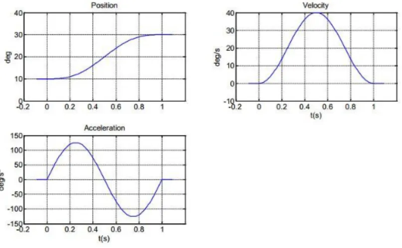
The basic type of planning is the point-point motion, in which the manipulator has to move from an initial to a final joint configuration in a given time. The end effector path is no concern. From a mathematical point of view a polynomial function is used. Is important to notice that, the higher the degree of the polynomial, the higher is the number of conditions that can be satisfied and the smoother the trajectory will be. According to all the considerations done, the minimum function required is a cubic polynomial
𝑞(𝑡) = 𝑎 + 𝑏(𝑡 − 𝑡𝑖) + 𝑐(𝑡 − 𝑡𝑖)2+ 𝑑(𝑡 − 𝑡𝑖)3
Imposing boundary conditions, the typical planning result is of the type of the one depicted in figure 5.
27
In industrial applications is a common practice to generate trajectories consisting of a linear profile adjusted at the beginning and at the end with parabolic bends. The resulting velocity profile has the typical trapezoidal shape (TVP) and the acceleration one is made of constant segments in the start and arrival phase.
In several applications, the path is described in terms of a number of points greater than two. For instance, even for the simple point-point motion of a pick and place task, it may be worth assigning two intermediate points between the initial and final ones, that can be representative of suitable positions for lifting off and setting down the object. For more complex applications it may be convenient to assign a sequence of points so as to guarantee better monitoring on the executed trajectories. The points are typically to be specified more densely in those segments of the path where obstacles have to be avoided or a high path curvature is expected. It should not be forgotten that the corresponding joint variables have to be computed from the operational space poses.
The problem of generating a path interpolating N points is usually accounted with a N-1 polynomial. This choice has some drawbacks:
• It is not possible to assign the initial and final velocities;
• The resulting system of equations to be solved for each constraint becomes computationally expensive;
• All the resulting coefficients are functions of all the defined points. If a point may be changed, all the polynomial coefficients must be re-computed.
The typical approach to overcome these drawbacks is to redefine the path in more low-order interpolating polynomials, taking into account the necessity to guarantee the continuity of the path over a point.
This type of interpolation can be performed with various algorithms such as polynomials, splines or lines & parabolas method.
Trajectory planning in the joint space yields unpredictable motions of the end-effector. When we want the motion to evolve along a predefined path in the operational space, it is necessary to plan the trajectory directly in this space. Trajectory planning in the operational space entails both a path planning problem and a timing law planning problem. The approach also changes in the case is important to consider only the position of the end-effector or also the orientation.
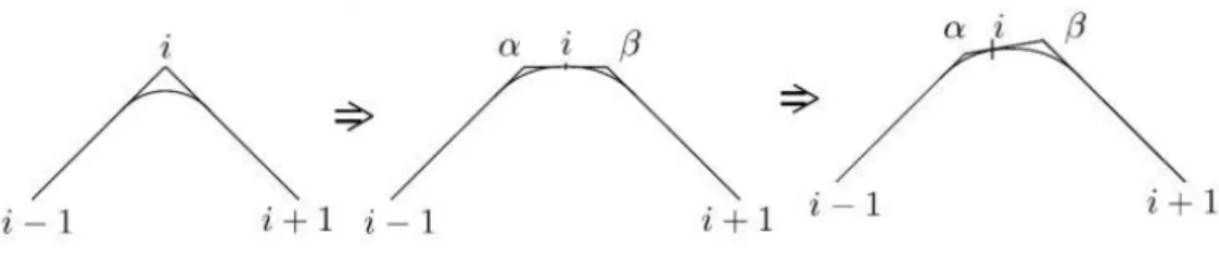
The most common types of paths required are linear paths, that are completely characterized once two points in cartesian space are given, and circular paths, that can be usually defined trough polar coordinates or trough the definition of three points in the cartesian space. These two basic types of path can be concatenated in order to obtain more elaborated paths. The concatenation is usually obtained trough a parametric parabolic path defined by a “via point”, a point that the path does not require to intersect. This behaviour is called over-fly. During the passage near a via point, the path remains always in the plane specified by the two lines intersecting in the via point. This means that the problem of planning the over-fly is planar.
28
Figure 7: over-fly
Once the basic concepts of robot motion planning are introduced, is possible to start talking about automatic path planning.
As expressed by L. Larsen, from German aerospace centre, in “Automatic path planning of industrial robots comparing sampling-based and computational intelligence methods”, “In times of industry 4.0 a production facility should be smart. One result of that property could be that it is easier to reconfigure plants for different products which is, in times of a high rate of variant diversity, a very important point. Nowadays in typical robot-based plants, a huge part of time from the commissioning process is needed for the programming of collision free paths. […] To speed up this process significantly, an automatic and intelligent planning system is necessary […]” [3].
Automatic path planning is required when obstacles are present and is necessary to plan motions that enable the robot to execute the assigned task without colliding with them. This means to generate a path that is collision free. The classical approach to this problem is to manually program a sequence of movement taking into account that the presence of obstacles in the working environment of the robot is known and usually fixed during the robot task execution. In this way the programmer is usually able to predict the possibility of collisions and write a sequence of commands in order to avoid that possibility.
Although the robot environment is usually known a priori in most of the industrial fields, the pose of the object to be manipulated can be random, such as in bin picking applications. In this case, a classical programming approach is useless and is necessary to find an algorithm that autonomously generate a geometric path, given the pose of the target, the kinematics of the robot and the known positions and shapes of the obstacles.
The algorithms capable to generate such results work typically at a high level of abstraction and, for this reason, they have implementations in different fields such as virtual reality or protein docking.
The classical planning problem is to find a continuous path from a starting to a final configuration without collision with the environment. The most famous challenge in this category is the “Piano Mover’s problem”: is required to find a path to move a piano from a starting to a final point of a room in which many objects are randomly placed.
29
Figure 8: piano-mover problem
The main problem is to find a way of representing the position of each point of the object to move and of the obstacles; this representation is typically called “configuration” and all the feasible configurations are grouped in the “configuration space”. The C-space typically is not a Euclidean space and its dimension is equal to the number of degrees of freedom of the object to move. Planning means to find a path in the C-space. In the C-space is possible to distinguish between portions of the space that are occupied by obstacles (Cobs) and
portions useful for the path generation (Cfree). Usually, for a small number of dofs, the path
in the C-space can be found trough discrete approaches: discretization means to divide the C-space in small portions and verify if these portions are free of obstacles. This means that the algorithm tries to move from a configuration to the next one until it is totally part of Cfree.
Figure 9: the C-space
If the configuration space has a high dimension the difficulty in the implementation of an analytical or discrete approach increases suddenly. Another category of algorithms is growing in the last few years to face this problem. These algorithms are called “sampling-based motion planning algorithms” and are nowadays the most used in industrial applications. The most important example is for sure the RRT (Rapidly-explored Random Trees). The basic idea is to sample the C-space, checking for a feasible, free configuration only after the sampling, instead of discretize and analyse all the C-space a priori, looking
30
for a free path only when the entire space is known. From this basic idea, different versions of the algorithm were born and will be analysed in the thesis in order to find the most suitable for the studied application, based on planning time and percentage of success. The basic idea behind all versions of the RRT algorithm is the following one but will be seen more in detail in the following chapters: the complete mapping net is not built. The algorithm, trough the sampling of the C-space, searches directly for a sequence of configurations capable to connect the initial and final configurations. The query is intrinsic in the sampling procedure. For this reason, at the end of the construction phase there will be only one completed path, the faster one, and the others remain uncompleted.
Figure 10: RRT mapping
The idea behind this thesis is to combine all these technologies, expanding motion planning features to the collaborative robotics capabilities provided by the Yumi robot. As already said in fact, motion planning algorithms just introduced are not directly studied for coordinated path planning of more then one moving entity. A smart approach for a correct movements management of Yumi must be developed, in order to help and speed up path computations, optimizing the whole procedure from a cycle-time point of view.
The result will be a smart, optimized, automatic bin picking procedure for collaborative assembling and manipulating procedures.
In this thesis, different algorithms will be tested and compared from some points of view. First of all, the planning time that is the most important parameter in order to ensure a high productivity for the typical applications of bin picking required by the companies. In fact, in most of the cases, the robot responsible of the bin picking function has to feed some other machines, responsible of one or more operations on the workpieces, that work with a predefined machining time. For this reason, is important to guarantee that, in any case, the planning time does not exceed a predefined threshold, or is preferable to start a new planning operation on the next detected workpiece. As we are going to see, the planning phase will depend on some configurable parameters and the variability on the results, for each algorithm, will be investigated.
31
Some other important aspects are, for example, the percentage of success as function of the position of the workpieces to grasp and the length of the computed trajectories that have an influence on the final robot actuation time.
32
3
R
OBOT KINEMATICS
3.1
STATIC AND KINEMATIC OF INDUSTRIAL ROBOTSThis chapter will be used to introduce and clarify most of the theoretical aspects related to industrial manipulator’s kinematics, starting from the basic algebra concepts, till the description of the files used to model robot kinematic chains in the present work of thesis. As already stated, the position and orientation of a robot’s end-effector can be described either in cartesian (workspace) or joint variables. Usually, these two spaces are related by a nonlinear system of equations that can be summarized by the expression below:
𝑆 = 𝐹(𝑄)
Where S is the vector of cartesian variables and Q is the vector of joint variables.
𝑆 = [ 𝑠1, 𝑠2, … . , 𝑠𝑛 ]
𝑄 = [ 𝑞1, 𝑞2, … . , 𝑞𝑚 ]
When the relation is written in that way, so Q is given and S is the unknown, the problem is of “forward kinematics”. In most of the industrial applications instead, the cartesian variables are given, because the final position of the end-effector defines the requirement of the task and the corresponding joint variables must be computed to guarantee the performing of the task. In this case is possible to talk about “inverse kinematics”, that can be written in the following way:
𝑄 = 𝐹−1(𝑆)
For open kinematic chains, that are the most diffused in the field of industrial manipulators for bin picking applications, this problem is usually more complicated respect to forward kinematics. The reason is in the difficulty in the inversion of the nonlinear relationships valid for the forward kinematics. As will be explained in this chapter, this problem is typically solved using numeric algorithms.
33
Figure 11: an open kinematic chain
The implementation of those algorithms requires the definition of the complete kinematics, so the evaluation of velocity and acceleration relationships, written both in direct and inverse form. The main advantage is that velocity and acceleration are defined by the differentiation of the position equation. This means that the following relationships will be linear and can be inverted in with less difficulties. Starting from the velocity equation, it can be defined as follows:
𝑆̇ = 𝜕𝐹
𝜕𝑄 𝑄̇ = 𝐽(𝑄) 𝑄̇
Where J is the jacobian matrix. It is the matrix expressing the linear relation between cartesian and joint velocities and it may be seen as the variable transmission ratio for complex, multi-degree-of-freedom mechanical systems. As is possible to understand, this relation is easier to invert, even if there is the drawback that the jacobian matrix is still position dependent; Anyway, in general, inverse kinematics, from the velocity point of view, is computationally not expensive as the position relation:
𝑄̇ = 𝐽−1(𝑄) 𝑆̇
Deriving the velocity equation is possible to obtain the acceleration relation for forward kinematics:
34
That can be inverted, obtaining the expression of joint accelerations:
𝑄̈ = 𝐽−1(𝑆̈ − 𝐽̇𝑄̇)
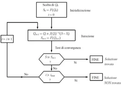
Once the complete kinematics is explained, is possible to introduce the main method used for inverse kinematics of serial manipulators. It is called Newton-Rhapson Method. It is a general algorithm used to find solution of no linear systems of equations. In case of systems made of one variable, it is called Gradient Method. It consists in an iterative procedure, based on the series expansion of the kinematic relation:
𝑆 = 𝐹(𝑄0) +
𝜕𝐹
𝜕𝑄(𝑄 − 𝑄0) 𝑆 = 𝐹(𝑄0) + 𝐽(𝑄 − 𝑄0)
𝑄 = 𝑄0+ 𝐽−1(𝑆 − 𝐹(𝑄0))
These passages can be generalized at the i-th iteration, obtaining the flow chart depicted in figure 12.
35
This algorithm, with a numeric approach, allows to find the joint variables, corresponding to a given cartesian pose, with a specified tolerance, after a number of iterations influenced by the initial guess of joint variables that must be performed to start the procedure.
3.2
STATICS OF THE RIGID BODY AND KINEMATIC CHAINS
Once the kinematics of a serial manipulator is known, is important to face with the problem of describing the position and orientation of each link of a robot respect to the previous one. The sum of all these informations allows to describe and model any type of manipulator, writing what is called “kinematic chain” of a robot. Having the knowledge of these concepts is of fundamental importance to manage the model of a robot from a mathematical point of view, without the necessity of strong and expensive graphical tools as, for example, CAD systems.
First of all, is important to clarify the basic mathematical representation of a rigid body in the space. The description of a kinematic chain will be simply the composition of a series of rigid body connected by joints. These joints can be revolute (the relative movement between the connected links will be a rotation) or prismatic (the relative movement will be a translation). The overall motion of the robot is achieved by the composition of elementary movements of each arm with respect to the previous one. In most of the application what is important to find is the final pose of the robot’s end effector respect to a known reference frame. This direct kinematics problem can be solved with a systematic matrix approach.
Figure 13: 3D object relative position
Considering a rigid body in a 3D space, described by its reference frame x’-y’-z’ with centre O’, its position respect to the world reference frame x-y-z is:
𝑜′ = [ 𝑜
36
The description of the relative rotation between the body reference frame and the world one is more complex and requires three unitary vectors, each of them describing the orientation of a body axes respect to all the world frame:
𝒙′= 𝑥𝑥′𝒙 + 𝑥𝑦′𝒚 + 𝑥𝑧′𝒛
𝒚′= 𝑦𝑥′𝒙 + 𝑦𝑦′𝒚 + 𝑦𝑧′𝒛
𝒙′= 𝑧
𝑥′𝒙 + 𝑧𝑦′𝒚 + 𝑧𝑧′𝒛
All the coefficients allowing the linear transformation from world to body reference frames are called direction cosines and can be summarized in the 3x3 rotation matrix R:
𝑅 = [
𝑥𝑥′ 𝑦𝑥′ 𝑧𝑥′
𝑥𝑦′ 𝑦𝑦′ 𝑧𝑦′
𝑥𝑧′ 𝑦𝑧′ 𝑧𝑧′
]
Each column of R corresponds to the unit vector of the orthonormal rigid body frame. This matrix, if well determined, has always the property to be orthogonal. The most important consequence is that:
𝑅−1= 𝑅𝑇
Rotation matrices are typically defined respect to the world frame. For this reason, is possible to define three matrices, one for each rotation respect to a fundamental axis.
37
The three fundamental rotation matrices can be defined as follow:
𝑅𝑧 = [ cos 𝛼 − sin 𝛼 0 sin 𝛼 cos 𝛼 0 0 0 1 ] 𝑅𝑦 = [ cos 𝛽 0 sin 𝛽 0 1 0 − sin 𝛽 0 cos 𝛽 ] 𝑅𝑥 = [ 1 0 0 0 cos 𝛾 −sin 𝛾 0 sin 𝛾 cos 𝛾 ]
As is possible to see, although each matrix is composed of 9 elements, only three independent parameters are required to completely describe the orientation of a body in a 3D space. This is called minimal representation of the orientation.
An arbitrary orientation in the space can always be defined as the combination of these fundamental rotations. From a mathematical point of view, this is obtained simply multiplying these three matrices. It’s important to underline that the final orientation of a body changes according to the specific sequence of rotations chosen, or, mathematically, by the sequence of multiplication of the rotation matrices. For this reason, some standard conventions were defined. The one chosen for this work is based on ZYX Cardan angles that can be summarized as follow:
• Rotate the reference frame by an angle α about axis z;
• Rotate the current reference frame by an angle β about the new y’ axis; • Rotate the current reference frame by an angle γ about the new x’’ axis.
The vector defining the position of a rigid body and the matrix defining its orientation can be combined in the so called Homogeneus transformation. It is usually a 4x4 matrix defined as follows:
𝑇 = [𝑅 𝑜′ 𝟎 𝟏]
Matrix T provides a compact, complete representation of the pose a rigid body in a 3D space. As for rotation matrices, also homogeneus transformation matrices can be combined, in order to describe the final pose of a body expressed as a sequence of given coordinate frames. This concept is of fundamental importance for describing the kinematic chain of an industrial manipulator.
38
Figure 15: 3D kinematic chain
𝑇06= 𝑇01𝑇12𝑇23… 𝑇56
As is possible to understand, although the T matrix have 16 values, it depends on only 6 independent parameters and being a rigid body in the space provided with six degrees of freedom, T is capable of describing its position exactly.
Homogeneus transformations are not the only way to describe the relative position and orientation of two rigid bodies. In the robotic field, the most important method is represented by the Denavit-Hatenberg parameters. This is a classical method, developed in the 60’s, used to formalize and standardize the way in which to choose and place the reference systems of a rigid body respect to the previous one, allowing an easy definition of an open kinematic chain. Following a method has the purpose of “automating” equation’s writing and simplifying some mathematical steps.
39
As it’s possible to see in figure 16, in the D-H convention, axis z is always the axis of movement of the link I respect to the link i-1. Based on this convention, the four independent parameters, needed to completely describe the relative pose of the link I respect to the link i-1 are the following:
• Distance a along axis x of link i-1; • Distance d along axis z of link i;
• Relative angle α respect to axis x of link i-1; • Relative angle θ respect to axis z of link i.
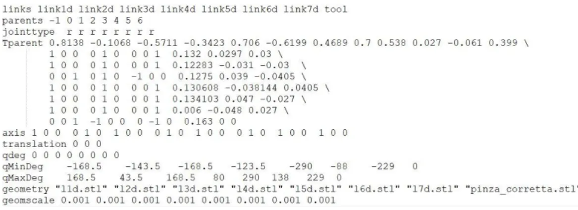
The developed software is able to accept both types description of a kinematic chain, but, in the specific case of the implementation on the Yumi robot, homogeneus transformations have been used, simply because these informations are already provided by the ABB company.
3.3
INVERSE KINEMATICS FOR REDUNDANT MANIPULATORSIn subsection 5.1 the direct and inverse kinematics of standard industrial manipulators has been presented. In that case, all the computations are based on the assumption that the joint and cartesian spaces have the same dimension. Under this assumption, all matrices are squared and it’s easier to solve all the differential kinematics, involving velocities and accelerations, that is based on the inversion of the jacobian matrix.
In the specific case of this thesis instead, is required to face with the motion planning problem of two robotic arms, both of them redundant.
A robot is kinematically redundant if the joint space dimension is bigger of the cartesian one, or, in other words, if it has more degrees of freedom than those strictly necessary to perform a task. In fact, from a more general point of view, redundancy is a relative concept: the number of task variables may be less than the dimension of the cartesian space. Kinematic redundancy can be exploited to:
• increase dexterity and manipulability; • avoid obstacles;
• avoid kinematic singularities; • minimize energy consumption; • increase safety.
For all these reasons, the majority of collaborative robots have redundant structures, because they are studied to mimic human capabilities and/or cooperate with human beings. Human arm in fact is a seven d.o.f system, without considering the degrees of freedom of the fingers. That’s because, also if we fully constrain the hand, there is still a possibility of movement (typically the elbow rotation)
40
Figure 17: human arm kinematics
Figure 18: Yumi's arm
Problems related to the inverse kinematics of a redundant robot are the existence of infinite solutions and the problem of self-motions: the robot may have internal undesired motions in the joint space which do not affect the pose of the end-effector in the tsk space.
The problem is to select a solution of the inverse kinematic procedure. This problem is typically addressed at velocity level:
𝑆̇ = 𝐽(𝑄)𝑄̇
Where J is a mxn matrix, in which m is the dimension of the task space and n is the dimension of the joint space. For redundancy m<n, so the Jacobian matrix is a lower rectangular matrix.