Intelligent Infrared CO2 Module
(Model: MH-Z19B)
User’s Manual
(Version: 1.0)
Valid from: 2016.01.21
Zhengzhou Winsen Electronics Technology Co., Ltd
ISO9001 certificated company
Statement
This manual’s copyright belongs to Zhengzhou Winsen Electronics Technology Co., LTD. Without
the written permission, any part of this manual shall not be copied, translated, stored in database
or retrieval system, also can’t spread through electronic, copying, record ways.
Thanks for purchasing our product. In order to let customers use it better and reduce the faults
caused by misuse, please read the manual carefully and operate it correctly in accordance with the
instructions. If users disobey the terms or remove, disassemble, change the components inside of
the sensor, we shall not be responsible for the loss.
The specific such as color, appearance, sizes &etc., please in kind prevail.
We are devoting ourselves to products development and technical innovation, so we reserve the
right to improve the products without notice. Please confirm it is the valid version before using this
manual. At the same time, users’ comments on optimized using way are welcome.
Please keep the manual properly, in order to get help if you have questions during the usage in the
future.
Zhengzhou Winsen Electronics Technology CO., LTD.
MH-Z19B NDIR CO2 Module
1. Profile
MH-Z19B NDIR infrared gas module is a common type, small size sensor, using non-dispersive infrared (NDIR) principle to detect the existence of CO 2 in the air, with good selectivity, non-oxygen dependent and long life. Built-in temperature compensation; and it has UART output and PWM output. It is developed by the tight integration of mature infrared absorbing gas detection technology, precision optical circuit design and superior circuit design.
2. Applications
MH-Z19B NDIR infrared gas module is widely used in * HVAC refrigeration
*Indoor air quality monitoring. *Smart home appliances *School
*Air cleaner
3. Main Functions and Features
High sensitivity, high resolution
od stability
4. Technical Parameters and Structure
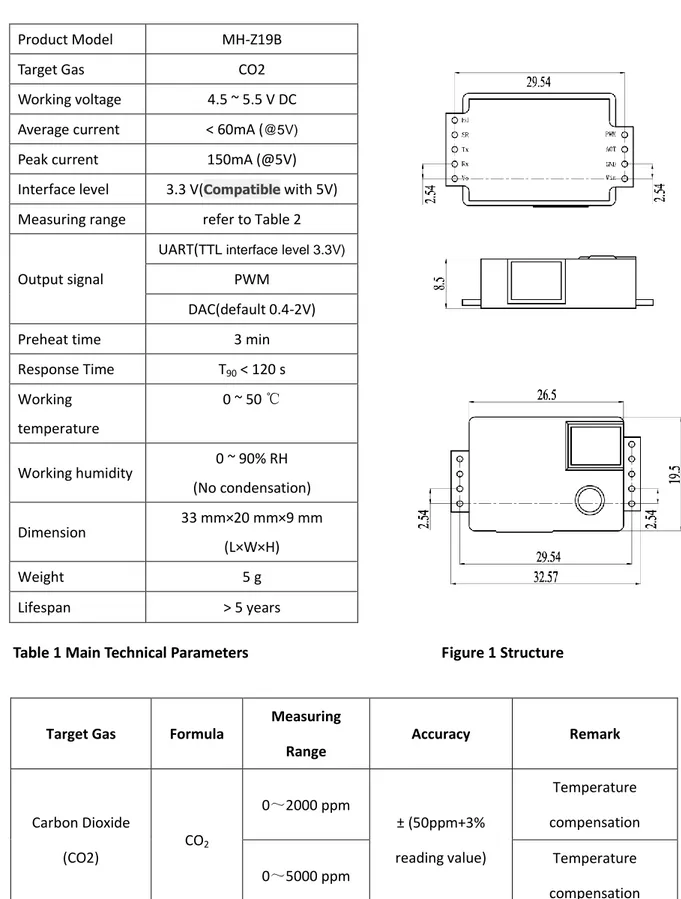
Product Model MH-Z19B
Target Gas CO2
Working voltage 4.5 ~ 5.5 V DC Average current < 60mA (@5V)
Peak current 150mA (@5V)
Interface level 3.3 V(Compatible with 5V) Measuring range refer to Table 2
Output signal
UART(TTL interface level 3.3V) PWM
DAC(default 0.4-2V)
Preheat time 3 min
Response Time T90 < 120 s Working temperature 0 ~ 50 ℃ Working humidity 0 ~ 90% RH (No condensation) Dimension 33 mm×20 mm×9 mm (L×W×H) Weight 5 g Lifespan > 5 years
Table 1 Main Technical Parameters Figure 1 Structure
Table 2 Measuring Range and Accuracy
Target Gas Formula
Measuring Range Accuracy Remark Carbon Dioxide (CO2) CO2 0~2000 ppm ± (50ppm+3% reading value) Temperature compensation 0~5000 ppm Temperature compensation
5. Product Dimensions
6.Pins
Pin
Definition
Vin
Vin
GND
GND
Vo
Analog output(0.4~2 V)or (0~2.5V)
PWM
PWM
HD
HD(zero calibration,low level lasting for
over 7s under low level is effective)
Rx
UART(RXD)TTL Level data input
7. Output
PWM output
Take 0~2000ppm for e.g
CO2 range 0~2000ppm
cycle 1004ms±5%
Cycle start high level output 2ms(theoretical value)
The middle cycle 1000ms±5%
cycle end low level output 2ms(theoretical value) CO2 level:Cppm=2000×(TH-2ms)/(TH+TL-4ms)
Cppm: CO2 level which calculated by PWM output
TH: high level output time during cycle
TL low level output time during cycle
UART OUTPUT Hardware
Connect sensor pin Vin-GND-RXD-TXD with 5V-GND-TXD-RXD.(Customers must use TTL level. RS232 level needs conversion)。
Software
General Settings
Baud Rate 9600 Data Bits 8 Stop Bits: 1 Parity(check bits): 0(NO)
Commands
0x86 Read CO2 concentration 0x87 Calibrate Zero Point (ZERO) 0x88 Calibrate Span Point (SPAN) 0x79 ON/OFF Auto Calibration 0x99 Detection range setting
0x86- Read CO2 concentration
Request
Byte0 Byte1 Byte2 Byte3 Byte4 Byte5 Byte6 Byte7 Byte8
Start Byte Sensor # Command - - - Checksum
0xFF 0x01 0x86 0x00 0x00 0x00 0x00 0x00 0x79
Response
Byte0 Byte1 Byte2 Byte3 Byte4 Byte5 Byte6 Byte7 Byte8
Start Byte Sensor # Concentration (High Byte)
Concentration (Low Byte)
- - - - Checksum
0xFF 0x86 HIGH LOW - - - - Checksum
CO2 concentration = HIGH * 256 + LOW 0x87-ZERO POINT CALIBRATION
Request
Byte0 Byte1 Byte2 Byte3 Byte4 Byte5 Byte6 Byte7 Byte8
Start Byte Sensor # Command - - - Checksum
0xFF 0x01 0x87 0x00 0x00 0x00 0x00 0x00 校验和
NO RESPONSE
0x88- SPAN POINT CALIBRATION
Request
Byte0 Byte1 Byte2 Byte3 Byte4 Byte5 Byte6 Byte7 Byte8
Start Byte Sensor # Command Span (High Byte)
Span (low Byte)
- - - Checksum
0xFF 0x01 0x88 HIGH LOW 0x00 0x00 0x00 Checksum
No response
E.g.: SPAN is 2000ppm,HIGH = 2000 / 256;LOW = 2000 % 256 Note: Pls do ZERO calibration before span calibration
Please make sure the sensor worked under a certain level co2 for over 20 minutes. Suggest using 2000ppm as span, at least 1000ppm
0x79- ABC logic on/off
Request
Byte0 Byte1 Byte2 Byte3 Byte4 Byte5 Byte6 Byte7 Byte8
Start Byte Sensor # Command - - - Checksum
0xFF 0x01 0x79 0xA0/0x00 0x00 0x00 0x00 0x00 Checksum
No response
Note: Byte3 is 0xA0,ABC on; Byte3 is 0x00, ABC off
All Winsen sensor with ABC logic on before delivery if no special request.
0x99- Sensor detection range setting
Request
Byte0 Byte1 Byte2 Byte3 Byte4 Byte5 Byte6 Byte7 Byte8
Start Byte Sensor # Command Detect range (high Byte) Detect range (low Byte) - - - Checksum
0xFF 0x01 0x99 HIGH LOW 0x00 0x00 0x00 Checksum
No response
Note: Detection range is 2000 or 5000ppm Detection range high byte=detection range/256 Detection range low byte=detection range/% 256
Checksum
Checksum = (NOT (Byte1+Byte2+Byte3+Byte4+Byte5+Byte6+Byte7))+1
Byte0 Byte1 Byte2 Byte3 Byte4 Byte5 Byte6 Byte7 Byte8
Start Byte Sensor # Command - - - Checksum
0xFF 0x01 0x86 0x00 0x00 0x00 0x00 0x00 Checksum
Calculating Checksum :
1、0x01 + 0x86 + 0x00 + 0x00 + 0x00 + 0x00 + 0x00 = 0x87 2、NOT:0xFF - 0x87 = 0x78
3、NOT+1:0x78 + 0x01 = 0x79
C language
char getCheckSum(char *packet) { char i, checksum; for( i = 1; i < 8; i++) { checksum += packet[i]; } checksum = 0xff – checksum; checksum += 1; return checksum; }
8.ZERO point calibration
Three methods: A: Manual calibration
Sensor HD pin with low level(0V) and lasting for over 7s(under 400ppm for at least 20 minutes) B:Command calibration(see above)
C: ABC logic function
Automatic Baseline Correction (ABC logic function)
ABC logic function refers to that sensor itself do zero point judgment and automatic calibration procedure intelligently after a continuous operation period. The automatic calibration cycle is every 24 hours after powered on. The zero point of automatic calibration is 400ppm. From July 2015, the default setting is with built-in automatic calibration function if no special request.
This function is usually suitable for indoor air quality monitor such as offices, schools and homes, not suitable for greenhouse, farm and refrigeratory where this function should be off. Please do zero calibration timely, such as manual or commend calibration.
9. Notes
9.1 Please avoid the pressure of its gilded plastic chamber from any direction, during welding, installation, and use.
9.2 When placed in small space, the space should be well ventilated, especially for diffusion window. 9.3 The sensor should be away from heat, and avoid direct sunlight or other heat radiation.
9.4 Do not use the sensor in the high dusty environment for long time.
9.5 To ensure the normal work, the power supply must be among 4.5V~5.5V DC rang, the power current must be not less than 150mA. Out of this range, it will result in the failure of the sensor. (The concentration output is low, or the sensor can not work normally.)
8.6 During the zero point calibration procedure by manual, the sensor must work in stable
gas environment (400ppm) for over 20 minutes. Connect the HD pin to low level (0V) for over 7 seconds.
Zhengzhou Winsen Electronics Technology Co., Ltd Add: No.299, Jinsuo Road, National Hi-Tech Zone,
Zhengzhou 450001 China
Tel: +86-371-67169097/67169670 Fax: +86-371-60932988