i
S
CUOLA
S
UPERIORE
S
ANT’
A
NNA
T
HE
B
IO
R
OBOTICS
I
NSTITUTE
P
H
D
P
ROGRAMME IN
B
IO
R
OBOTICS
Stiffness tuning in Soft Robotics
S
UPERVISOR
P
H
D
C
ANDIDATE
Dr. Matteo Cianchetti Mariangela Manti
T
UTOR
Prof.ssa Cecilia Laschi
XXIX Doctoral Cycle
June 23
th, 2017
iii
A babbo e mamma, perchè mi avete insegnato ad essere forte. Ed io sarò forte per voi, con voi! Grazie, Mariangela
iv
Abstract
The need for building a new generation of robots using soft materials comes out from considerations regarding the main limitations of traditional robots in negotiating natural environments with respect to the compliance and adaptability demonstrated by animals. Nature teaches that inherent softness enables dexterity and safe cooperation, but stiffness is required for effective exchange of forces during interactions with the environment.
Taking inspiration from biological systems, the focus of soft robotics research has been entirely devoted to the design and development of innovative actuation strategies for an on-demand control of such deformability and compliance.
In literature, two different approaches for achieving this goal emerge: the first one, typically experienced when working with soft materials-based actuators, exploits the stiffening implied in the material deformation when actuation happens, while the second one refers to the capability of inducing a change in the elastic modulus, without motions.
In the framework of this Ph.D. thesis, the second approach has been investigated. In particular, passive, active and semi-active stiffness tunings have been studied in two robotic applications. The first strategy plays with intrinsic mechanical properties of the soft material in order to get a specific stiffness value; the second one takes advantage of an antagonistic arrangement of the actuators in the soft system for determining stiffness modulation; the third one uses semi-active technologies to dramatically change the intrinsic passive mechanical properties of the material itself.
The most suitable soft actuation technologies have been identified and their working principles have been tested with respect to technical requirements, in order to define advantages and limitations. Once the range of the suitable soft technologies has been mastered, new design concepts have been proposed as solutions for stiffness tuning in the framework of the following applications:
(i) The development of a vocal fold prototype as the first, fundamental, step for a human larynx simulator, based on the specifications given by the research group in otorhinolaryngology of the Pisa University hospital led by Prof.
v Ursino. The passive response of the multi-layered structure has been investigated by capitalizing on the intrinsic mechanical properties of silicone used. Soft materials have been designed for obtaining the necessary stiffness gradient in the vocal fold cross section. Moreover, the action of the cricothyroid and the thyroarytenoid muscle on the vocal fold modulation has been replicated by using a linear actuator and a shape memory alloy wire, respectively. This last activity has been carried out under the supervision of Prof. Jonathan Rossiter and Dr. Andrew Conn, at the Soft Robotics Lab, in Bristol.
(ii) The development of a soft manipulator as personal care robot in the framework of the I-Support research project. Soft robotics technologies have been combined in order to provide advanced manipulation capabilities to the robot, for a safe human-robot interaction. Two technological concepts have been investigated for stiffness modulation: the first one is based on the antagonistic arrangement of active elements (cables and flexible fluidic actuators); the second one combines a cable-driven mechanism with the layer jamming semi-active technology.
In addition to these applications, the jamming technology has been studied and used for the development of a device able to replicate the shape of an object with high accuracy, by exploiting the transition between a compliant and a rigid state. The proof of concept has been extensively tested, providing the ground to further improvements, capitalized into a patent.
For each application, the suitable soft technology has been chosen and designed in order to meet the technical requirements. Prototypes have been realized spending efforts in the definition of custom and reliable manufacturing procedures (of paramount importance in new technologies). Testing has been carried out with custom-designed experimental set-ups for encompassing all the hardware components. Data analysis allowed to test adequacy and ability of the technologies of meeting the stiffness requirements of the soft-bodied system.
vi
Contents
List of Figures ... x
List of Tables ... xvii
Introduction ... 1
Research context ... 1
Chapter 1 – State of the art ... 5
1.1. Active technologies ... 6
1.1.1. Active-Active ... 7
1.1.2. Active-Passive structure ... 9
1.2. Semi-Active technologies ... 11
1.2.1. Magneto and Electrorheological materials ... 11
1.2.2. Low Melting points materials and Glass- transition-based softening ... 12
1.2.3. Shape Memory Materials and other intrinsic mechanisms ... 13
1.2.4. Material jamming ... 14 1.2.4.1. Manipulators ... 15 1.2.4.2. Gripper ... 17 1.2.4.3. Locomotion ... 18 1.2.4.4. User interfaces ... 19 1.3. Conclusion... 20
Chapter 2 – Passive stiffness tuning ... 24
2.1. Physiology of the human larynx ... 24
2.2. Design of multilayer vocal fold prototype ... 30
2.3. Soft materials and characterization tests ... 31
2.4. Fabrication procedure ... 37
vii
2.6. Experimental set-up and trials ... 40
2.7. Results and Discussion ... 41
2.7.1. Oscillation frequency at the onset pressure ... 41
2.7.2. Computational model ... 41
2.7.3. Glottal width ... 43
2.7.4. Subglottic pressure ... 44
2.8. Conclusion... 45
Chapter 3 – Active stiffness tuning ... 47
3.1. Vocal fold simulator ... 48
3.1.1. The Cricothyroid muscle ... 48
3.1.1.1. Design and development of a monolithic and a bonded sample embedding a vocal fold ... 49
3.1.1.2. Experimental set-up and tests ... 51
3.1.1.3. Results and discussion ... 54
3.1.2. Thyroarytenoid muscle ... 64
3.1.2.1. Design and manufacturing of the prototype ... 65
3.1.2.2. Preliminary experimental results and discussion ... 66
3.1.3. Conclusion ... 70
3.2. Soft manipulator as assistive robot for elderly people ... 72
3.2.1. Manipulator overview: technical requirements ... 76
3.2.2. Design and manufacturing of the α-prototype ... 78
3.2.3. Kinematic characterization of the module ... 81
3.2.4. Experimental evaluation of motion capabilities ... 81
3.2.5. Stiffness characterization and reachable workspace ... 83
3.2.6. Results and discussion ... 85
viii
3.2.6.2. Stiffness capabilities and reachable workspace ... 90
3.2.7. Design and manufacturing of the β-prototype ... 94
3.2.8. Stiffness modulation ... 95
3.2.9. Experimental set-up ... 97
3.2.10. Results and discussion... 98
3.2.10.1. Workspace identification ... 98
3.2.10.2. Stiffness characterization ... 99
3.2.11. Three-modules soft manipulator ... 101
3.2.11.1. Hardware ... 102
3.2.11.2. Control ... 104
3.2.11.3. Experimental set-up ... 105
3.2.11.4. Results and discussion ... 106
3.2.12. Conclusion and future works ... 108
Chapter 4 – Semi-active stiffness tuning ... 110
4.1. Two-modules manipulator ... 110
4.1.1. Design and manufacturing of the module ... 113
4.1.1.1. Layer jamming ... 113
4.1.1.2. Assembly of the final module ... 114
4.1.2. Experimental set-up ... 115
4.1.3. Experimental protocol for stiffness characterization ... 116
4.1.4. Results and Discussion ... 118
4.1.5. Conclusion ... 122
4.2. JamFit ... 123
4.2.1. Design and operating principle of JamFit ... 124
4.2.2. Technology exploitation ... 125
ix
Chapter 5 - Conclusion ... 127
Research products ... 131
References ... 137
x
List of Figures
Figure 1.1 (I) A scheme of two DEAs used to form a variable-stiffness actuator. In (a), the two DEAs are unconnected and in unloaded equilibrium positions. When connected (b), the structures are prestressed in tension. Thus, the activation of one of them (c and d) produces a release of the prestress and a consequent displacement x of the central reference point. When the actuators are both activated (e), they both decrease the lateral prestress, which in turn decreases the stiffness of the system (not of the actuators themselves) without changing the equilibrium position (isometric stiffness variation). (II) The simultaneous activation of contracting and expanding McKibben actuators proposed in [13] to obtain a variable-stiffness device. (III) (i) A description of the main components of tendon-fluidic mechanisms; their implementation in (ii) and (iii) the AirOctor [15] and (iv) a surgical manipulator able to shrink almost completely [18]. .... 9 Figure 1.2 (I) A FEM simulation of a McKibben actuator with θ0 = 54.7° from [19]. (II)
The scheme of the muscle arrangement in the octopus muscular hydrostats from [7]: in (a), four main longitudinal muscles (L) are arranged along the arm length; transverse muscles (T) are arranged in a radial configuration along four arcs connecting the external connective tissue with the central channel, which contains nerve fibers (N); oblique muscles (O) wrap the whole structure [25]. (b) A histological transverse section of the same muscular system [25]. Longitudinal (c) and transverse (d) views of the robotic actuator proposed in [22], with SMA coils replacing the longitudinal and transverse muscle bundles of the muscular hydrostats. (III) The function of a multilayer variable-stiffness device: (a) compliant, (b) partly stiffened and (c) stiff. ... 11 Figure 1.3 Material jamming examples grouped into: Manipulators (I) a CAD drawing showing a cross-sectional view of the manipulator developed by Cheng et al. [42], (II) a CAD drawing showing the design of the single module with all the structural elements (soft-bodied module with fluidic and the stiffening chambers) [62], (III) an assembled one-side flap pattern with a section view of a double-side flap pattern and a real assembled double-side flap pattern [51]; Gripper (IV) a schematic drawing of the jamming-based gripper for picking up a wide range of objects without the need for active feedback [43]; Locomotion (V) a side view of the proposed jamming-based soft robot with three unjammed cells and the internal actuator partially inflated [53], (VI) the
xi basic configuration of the locomotion system of the amoeba robot [54]; User interface (VII) the jamming technology for haptic feedback [55], (VIII) JammJoint wearable robot, (IX) the working principle of three different jamming-based approaches tested on top of a PneuFlex actuator. From top: granular jamming, layer jamming with overlapping fish-scale-like layers, and layer jamming with two stacks of three interleaved layers. The PneuFlex actuator is shown on the bottom, and the jamming chamber is indicated by dashed lines [60], (X) a granular jamming cap for non-invasive, rigid fixation of fiducial markers to the patient [61]. ... 20
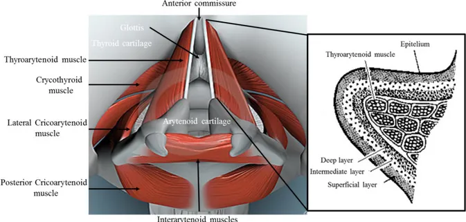
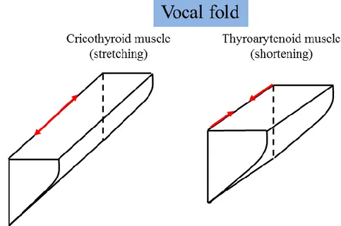
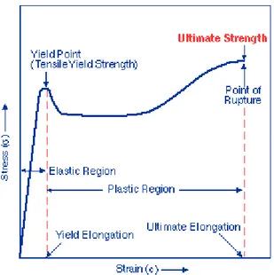
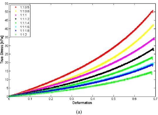
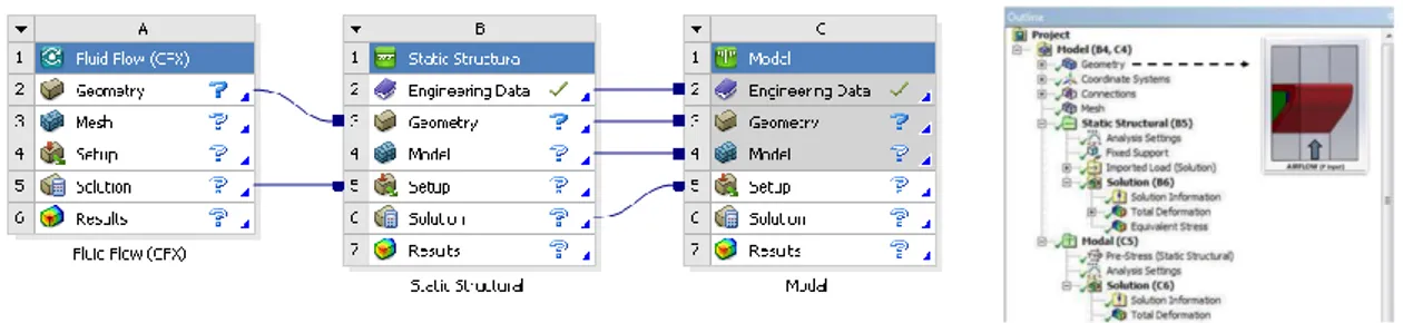
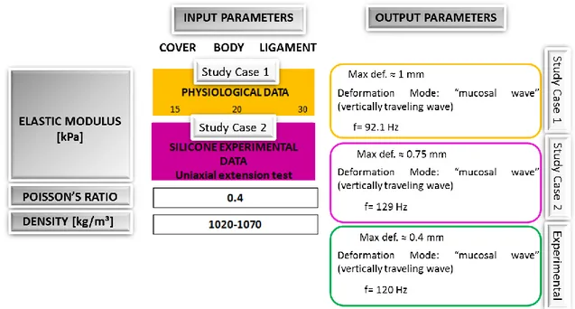
Figure 2.1 Intrinsic muscles of the human larynx (ID 1663329 © Tigerx| Dreamstime.com) with the histology of the layered structure of the vocal fold (adapted from http://housecentral.info/l/lamina-propria-vocal-folds.html). The aryepiglottic muscle, as an intrinsic muscle, is not visible in the superior view. ... 27 Figure 2.2 The stretching and shortening effects of cricothyroid and thyroarytenoid muscles on vocal folds, respectively. ... 28 Figure 2.3 Vocal fold model: (a) geometry (adapted from [71]), (b) CAD model. ... 31 Figure 2.4 Stress-strain curve for a typical thermoplastic (Mould Z., http://www.zhilianmould.com/blog/stress-strain-curves-for-unfilled-polymers/). ... 33 Figure 2.5 (a) True stress-strain curves and (b) Elastic Modulus of different silicone mixing ratios. Data refers to the mean and standard deviation of three different samples for each mixing ratio. ... 35 Figure 2.6 (a) Elastic, G’, and (b) Viscous, G’’, shear moduli for different silicone mixing ratios. ... 36 Figure 2.7 Multiphase casting procedure. Step I: casting of cover layer with mixing ratio 1:1:1.8; Step II: casting of ligament layer with mixing ratio 1:1:1; Step III: casting of body layer with mixing ratio 1:1:1.4. Final multi-layered vocal fold prototype. ... 38 Figure 2.8 Fluid structure interaction analysis in Ansys. The system is represented by a single vocal fold constrained in a trachea-like shape with a rectangular cross-section in order to better deal with the symmetry of the system. ... 39 Figure 2.9 Full (a) and hemi (b) larynx configuration ... 40 Figure 2.10 Experimental results of the computational model related to the hemi-larynx configuration for two study cases, as follows: the yellow box reports the values for the
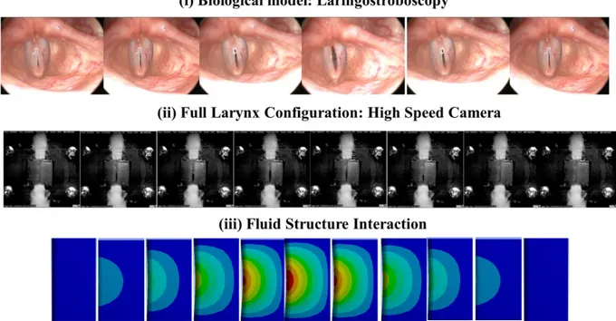
xii constant elastic modulus for each layer as referred in literature [72]; the purple box implements a virtualization of the stress-strain data from the mechanical characterization. Both study cases are represented with the output parameters. These results are compared with the experimental ones related to the hemi-larynx configuration, summarized in the green box. ... 42 Figure 2.11 Deformation of the vocal fold for (I) study case 1 and (II)-(III) study case 2 with respect to the experimental results for the hemi-larynx configuration. ... 43 Figure 2.12 Glottal width modifications during an oscillation cycle for the (i) biological model, (ii) fully larynx configuration and (iii) computational model. For the biological model, pictures are recorded during a laringostroboscopy at increasing time steps in order to show the closing and opening phase of the vocal folds. For the experimental model, the oscillation is recorded with an high speed camera and specific frames are used to show the main phases of the glottis during the oscillation cycle. For the computational mode, top view images of the vocal fold during a cycle of simulation of the fluid-structure interaction are reported. ... 44 Figure 2.13 Subglottic pressure recorded in (a) human subjects [89] and (b) the full larynx configuration. ... 45
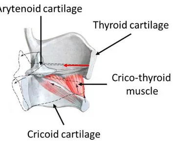
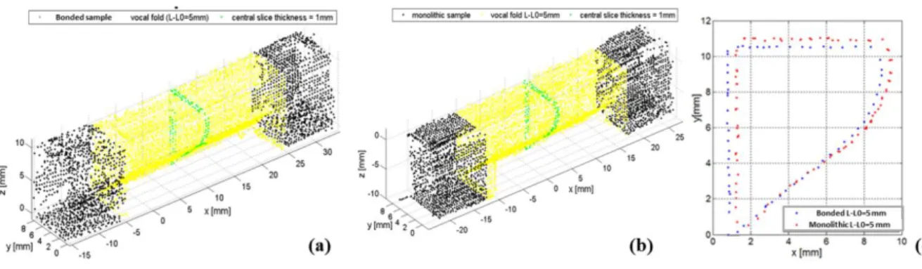
Figure 3.1 The activity of the cricothyroid muscle is depicted (adapted from http://beverlyhillsvoice.com/patient-information/laryngeal-anatomy/). ... 49 Figure 3.2 It shows the design and manufacturing of the monolithic and bonded samples containing a vocal fold in the linear portion. The sample has been obtained by properly scaling the dumb-bell sample in reference to the ISO. 37:2005 (E). ... 50 Figure 3.3 Experimental set-up for the static tests. (a) 3D shape reconstruction with the use of a Laser Scanner; (b) Force-displacement relationship has been carried out using a load cell connected in series to the sample. ... 52 Figure 3.4 Experimental set-up for dynamic tests composed of: (i) linear actuator, (ii) silicone sample, (iii) microphone, (iv) DAQ for managing the airflow and pressure sensors and (v) High frame rate camera. ... 52 Figure 3.5 3D shape reconstruction for the (a) bonded and (b) monolithic sample when a displacement of 5 mm is applied. (c) The central slice of both samples (1 mm in thickness) is extracted and compared. ... 54
xiii Figure 3.6 The 3D shape reconstruction for the bonded sample made of Ecoflex 0030 is shown. The yellow portion represents the vocal fold section under investigation: a moving window is applied to this region and the outline of the cross section is captured thanks to a Savitzky-Golay FIR smoothing filter. The first and the last slice are shown, as representation of the entire analysis. ... 56 Figure 3.7 Mean value and the error bar representing the standard deviation of the cross section variation at increasing displacements (L-L0) for the Bonded sample made of
EcoFlex 030. ... 57 Figure 3.8 The quantitative evaluation of the real displacement is shown. ... 58 Figure 3.9 The stress-strain response of the vocal fold is shown. ... 58 Figure 3. 10 Sound analysis is shown with the fundamental oscillation frequency in red [Hz], energy represented in red [dB] and complete spectrum with the fundamental and the harmonic series [Hz] for: (a) ΔL=0 mm (0% of strain), (b) ΔL= 5 mm (4% of strain); (c) Δ=10 mm (14% of strain) and (d) ΔL=1 mm (24% of strain). ... 63 Figure 3.11 A schematic representation of the activity of the thyroarytenoid muscle is shown (adapted from http://beverlyhillsvoice.com/patient-information/laryngeal-anatomy/). ... 65 Figure 3. 12 Detail of the mold and different views of the prototype. ... 66 Figure 3.13 Different activation levels of the active vocal fold. Increasing current values are applied to the alloy up to a maximum of 300mA. (i) 0V/0A, (ii) 1V/0.13A, (iii) 2V/0.27A and (iv) 2.20V/0.30 A. This last value is a threshold and causes a buckling effect on the rear region. ... 67 Figure 3.14 Experimental set-up for the dynamic tests on the vocal fold with the SMA. ... 68 Figure 3.15 Fundamental frequency for an activation current of (a) 200 mA and (b) 300 mA. ... 69 Figure 3.16 Thermal images of the (a) back and (b) frontal region of the vocal fold when a current of 300 mA is applied. ... 70 Figure 3.17 Soft manipulator configuration with respect to the users' target body regions. ... 77 Figure 3.18 CAD model of the single module with the cross section on the right top. P1-P2-P3 represent the flexible fluidic actuators while T1-T2-T3 represent the cables. ... 78
xiv Figure 3.19 Flow chart showing the fabrication process for the single McKibben-like actuator. Last two pictures show the final prototype with three cables, three
McKibben-like actuators and the central channel for the provision of water/soap. ... 80
Figure 3.20 Experimental set-up for the evaluation of motion capabilities. ... 83
Figure 3.21 Experimental set-up for stiffness and workspace investigation. ... 85
Figure 3.22 Flexible fluidic actuator response at increasing pressure values. ... 86
Figure 3.23 Bending performances of the two activation patterns. (a) 3D view, xz view and yz views of pattern 1 (P1+T1); (b) 3D view, xz view and yz views of pattern 2 (P2P3 – T2T3). ... 89
Figure 3.24 Bending angle of the module at increasing pressure values for one flexible fluidic actuator (red line), two flexible fluidic actuators (blue-line). ... 89
Figure 3.25 Elongation–contraction module characterization. The blue marker represents the starting configuration without active elements. ... 90
Figure 3.26 Activation pattern with a single cable (T1 in Figure 3.18) up to the maximum position and activation of the opposite chamber (P1 in Figure 3.18). (a) Global bending movement of the element; (b) xz view; (c) yz view. The last portion of the graph is related to the stiffening of the module: the Arrows indicate the tip orientation during the movement; green-blue-red represent x-y-z axes. ... 91
Figure 3.27 Activation pattern with two cables (T1 – T2 in Figure 3.18) up to the maximum position and activation of the two opposite chambers (P2 – P3 in Figure 3.18). (a) Global bending movement of the element. (b) xz view. (c) yz view. Arrows indicate the tip orientation during the movement; green-blue-red represent x-y-z axes. 92 Figure 3.28 Workspace evaluation for the single module. The blue point represents the initial position of the module in an un-activated state. (b) Workspace view from the X– Y plane. (c) Workspace view from the X–Z plane. (d) Workspace view from the Y–Z plane. ... 94
Figure 3.29 (a) CAD model of the β-prototype, based on three flexible fluidic actuators (P1, P2, P3) and three cables (T1, T2, T3) highlighted in the section view; (b) the hardware prototype with its constitutive elements. ... 95
Figure 3.30 Top view of the module with two bending configurations: (a) two cables (T2-T3) and one chamber (P1) in bending plane 1, (b) two chambers (P1-P2) and one cable (T3) in bending plane 2 (BP2). ... 97
xv Figure 3.31 Experimental set-up. ... 98 Figure 3.32 (a) Isometric workspace view. The stiffness variation (referred to as the stiffness map) in two regions corresponding to the two bending base configurations is also highlighted. (b) Workspace view in the XY plane (c) Workspace view in the YZ plane (d) Workspace view in the XZ plane. (NOTE: in the graph axes are in [mm] for a better visualization) ... 99 Figure 3.33 Axial force measurements (a) Configuration I: Bending due to one chamber and two cables (b) Configuration II: bending due to two chambers and one cable (c) Configuration III: elongation/contraction due to three chambers and three cables. Each figure has a legend represented by a table with 6 values: P1-P2-P3 represent the active pressure [bar] for each chamber while T1-T2-T3 indicate the servomotor rotation [deg] for each cable. Legend in (a) refers to the set of input parameters for Configuration I; legend in (b) refers to the set of input parameters for Configuration II while legend in (c) reports the set of input parameters for Configuration III. ... 101 Figure 3.34 Overall overview of the soft manipulator. Moreover, it shows the arrangement of cables for the proximal, middle and distal (PT, PM, PD) modules and pneumatic flexible fluidic actuators for the proximal, middle and distal modules (PFFA, MFFA and DFFA) along the soft bodied system. ... 103 Figure 3.35 Schematic view of the hardware platform. ... 103 Figure 3.36 (a) Experimental set-up composed of the soft manipulator with the hardware components and 6-cameras Vicon tracking system; (b) Vicon interface: three markers identify the end regions of each module. ... 105 Figure 3.37 Reachable workspace of the three-modules soft arm; (a) xyz-view; (b) xy-view, (c) xz-view and (d) yz-view. ... 106 Figure 3.38 The current scenario of the first validation round of the soft manipulator. ... 107 Figure 3.39 Soft manipulator mounted on the wall with a detail of the cross section showing the cables and the pneumatic chambers exploited for the task. ... 108
Figure 4.1 Overall overview of the two-modules manipulator. The upper part of the figure shows details regarding the arrangement of the actuation elements across each module. ... 111
xvi Figure 4.2 Planar and cylindrical view of a portion of the layer jamming skeleton (three layers shown). ... 113 Figure 4.3 Multi-steps manufacturing procedure for the proximal module that is based on a cylindrical layer jamming concentric with respect to three cables, spaced at 120° in a circle of 60mm in diameter. (I) Single rings made of acetate are cut and (II) connected in a cylindrical structure; (III) an outer and inner membranes envelop the layer jamming; (IV) a bellow-shape structure covers the module and provides support to discs that drive the path of the cables. ... 115 Figure 4. 4 Experimental set-up for stiffness characterization of the layer jamming-based module. ... 116 Figure 4.5 Summary of axial and lateral force response for the activation pattern 1 at different bending angles of the module: (a) 50°, (b) 70° and (c) 90. Legend refers to the notation introduced in the Table 4.1. ... 119 Figure 4.6 Summary of axial and lateral force response for the activation pattern 2 at different bending angles of the module: (a) 50°, (b) 70° and (c) 90°. Legend refers to the notation introduced in Table 4.1. ... 120 Figure 4.7 Comparison in terms of axial force recorded for the jamming-based module (cyan line) and the β-prototype (dotted lines), for (a) CASE A and (b) CASE B (i.e. the same amount of cable is pulled/released in the jamming-based module and β-prototype, respectively). NOTE: The legend for the dotted lines refers to the notation introduced in Figure3.33 of Section 3.2.10.2 (three pressure values and three servomotors rotation) while the cyan line refers to two configurations of the jamming-based module. ... 122 Figure 4.8 Multistep procedure describing the working principle of JamFit. Final results show the accuracy of the device in the registration of some details of the shoe. ... 125 Figure 4.9 Design concept of the double-cavity membrane (patent n. 102016000087547). ... 126
xvii
List of Tables
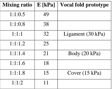
Table 1.1 The classification of the main soft robotics actuation technologies [5]. ... 6 Table 1.2 Direct comparison of stiffening mechanisms (qualitative evaluation scale: ++, +, o, -, -- from the highest to the lowest values)...……....23 Table 2.1 Mixture ratios by weight of Part A : Part B : Silicone Thinner, resulting Elastic Modulus of the individual silicone samples and the individual layer of the vocal cord simulator (elastic properties of human vocal fold tissue [72]) ... 34 Table 3.1 A summary of the design of some examples of soft robotic manipulators…...74 Table 3.2 Summary of lateral forces applied in elongation/contraction and bending configurations for the β-prototype………...100 Table 4.1 Summary of the tested configurations for stiffness characterization. Despite the servomotors configuration it is provided the associated label in blue for the activation pattern (1) and (2). (NOTE: the different configurations are represented in terms of rotation of the pulley in the servomotor. For example: 0040 means 0° for servomotor 1-2 and 40° for the third one, in charge of the bending motion. As a reference, please consider that 10° corresponds to a cable contraction of 0.3 cm)………...116
1
Introduction
The present Ph.D. thesis has been developed in the framework of Soft Robotics. More in detail, it looks at the importance of variable stiffness mechanisms for building innovative robots made of compliant materials, that are able of negotiating unpredictable environmental contexts. This research moves from the scientific challenge of replicating the biological capabilities of controlling compliance of soft-bodied elements towards the definition of technological concepts oriented to the target scenario. In particular, two different applications have been studied:
the development of a biorobotic vocal fold model where it is possible to passively or actively change the stiffness of the structure, by mimicking the role played by the thyroarytenoid (TA) and cricothyroid (CT) muscles;
the development of a soft manipulator, as an assistive robot for elderly people, able to safely interact with the user for accomplishing the shower task.
Research context
Bio-inspiration and bio-mimetic cover a pivotal role in the development of soft systems that are able to safely interact with fragile objects such as the environment, food and human beings. Moreover, bio-inspiration and bio-mimetics have provided the ground for the growth of Soft Robotics that nowadays is included among the most promising and innovative robotics field thanks to the continuous identification and advancement of novel and versatile technologies [1], [2].
Biological inspiration does not imply that we attempt to copy nature. Rather, the right methodology is to understand the principles underlying the behavior of animals and humans and transfer them to the development of robots [3]. With this in mind, researchers tackled the challenge of developing a set of enabling technologies that have
2 involved a renovation in the engineering of robots. Current systems have complex skill set, they are capable of dexterous movements and safe cooperation with humans.
Nature teaches that the inherent softness enables dexterity and safe cooperation, but stiffness is required for exchanging forces during effective interactions with the environment and human beings.
The natural world provides some examples of soft structures with variable stiffness, relying on the ‘muscular hydrostat’, mainly composed of muscle tissue. These structures are capable of diverse and complex movements and their working principle is unusual because the musculature generates both the force for movement and provides skeletal support. These abilities are achieved in a similar way to conventional hydrostatic skeletons (typically cylindrical, fluid-filled cavities surrounded by a muscular wall that is reinforced with connective tissue fibres) namely, by exploiting the incompressibility of muscle (mostly made of water) at physiological pressures and arranging the musculature to control all three dimensions [4].
This simple principle serves as the basis of support and movement in soft-bodied animals such as: the octopus is able to selectively stiffen portions of its arms to use them as a modifiable skeleton; the elephant with its trunk can do the same to transmit very high forces [5].
The complex structure of the hydrostat muscle has represented a source of inspiration for soft robotics' researchers. In particular, the literature demonstrates that the understanding of the morphology and functionality of such soft structure in nature is a preliminary step towards new design concepts in soft robotics [6], [7].
The key principle is that soft structures exploit the possibility of selectively switching between a soft state to a stiff one, for a more efficient interaction, with respect to the traditional robotic systems that exploit their intrinsic stiffness for applying forces to the environment.
Selectively means that soft robots, as the first instance, take advantage of their soft body to easily deform and pass through a small aperture or to carefully interact with objects, surfaces or human beings; then, specific body sites transit to a stiff state thus generating and transferring forces.
This feature has been translated in the following technological challenges for researchers: (i) catching new strategies for imbuing materials with intelligence and
3 promoting these innovative capabilities, (ii) developing new technologies for actuation and sensing and (iii) research of unconventional control techniques. All of these elements represent the ingredients for building robots with the ability to change and control inherent deformability and compliance [5].
In soft robotics, there are two possible approaches for obtaining stiffness change: (i) exploiting material deformation, commonly experienced when dealing with soft materials-based actuators; (ii) exploiting the change of mechanical properties (in terms of elastic modulus) but without motions.
In the framework of the present Ph.D. thesis, it has been considered the second way (ii) and in particular three different approaches are investigated and employed (Passive, Active and Semi-Active) for an on-demand stiffness modulation for different soft structures. The thesis is organized as follow:
Chapter 1 presents a literature review regarding soft robotics technologies used for a stiffness modulation in soft-bodied structures, with respect to all three approaches. Among all the suitable technologies, some of them have been selected, according to the purpose and the context of the thesis. Firstly, the working principle has been figured out and then, how it is implemented in different scenarios reported in literature. Particular attention will be paid to some technical and critical aspects such as: (i) materials and manufacturing procedures involved in (it will be clear how there are not standard manufacturing procedures when dealing with novel and emerging technologies but everything has to be defined and faced from a scratch), (ii) integration strategies within the soft-bodied structure and (iii) qualitative and quantitative analysis of the performances (formalization of an efficient study protocol and design of custom experimental set-up).
Chapter 2 describes the passive approach used for the development of a multi-layered soft structure mimicking the vocal fold and its experimental testing. In particular, the use of the most common soft materials (silicone) will be presented (together with the manufacturing procedures) for obtaining a structure with a stiffness gradient across its section.
4 Chapter 3 mainly focuses on the active way for tuning the stiffness into two different contexts: (i) the use of technologies for mimicking an active vocal fold structure capable of changing its mechanical properties and shape, as the effect of the cricothyroid and thyroarytenoid muscles activities; (ii) the design and development of a new McKibben-based actuator acting in combination with cables, as constitutive elements for a soft modular manipulator for assistive robotics.
Chapter 4 describes the design and development of semi-active solutions for changing the stiffness into two different scenarios: (i) a soft robot arm module based on layer jamming and a (ii) granular jamming-based system for effectively replicating the shape of objects of whatever shape, dimension or material.
Chapter 5 summarizes the main achievements of this work pointing out perspectives for future works.
5
Chapter 1 – State of the art
The present work tackles the technological challenge of designing and developing soft robotics systems able to exploit variable stiffness adapting its compliance with respect to external and unknown environment.
As mentioned in the introduction, there exist two typically strategies for stiffness tuning: (i) the use of soft materials-based actuators and (ii) the change of the intrinsic mechanical properties of the soft body itself. The second approach has been investigated and exploited into different bio-robotics applications, as it will be explained in the next sections.
Literature analysis reveals that on-demand stiffness can be obtained, as follows:
PASSIVE: the stiffness/compliance of the device is due to the intrinsic passive mechanical properties of the soft material;
ACTIVE: the passive properties are modulated through active actuation elements which act antagonistically;
SEMI-ACTIVE: the stiffness of the materials can be varied with semi-active actuators, which are only able to change their passive mechanical properties. Despite the passive approach does not provide any manoeuvre margin because it is strictly related to the elastic properties of the material employed for the soft-body, the other two ones offer different technological strategies for stiffening, such as: the use of active actuators arranged in an antagonistic manner and the use of semi-active actuators that can change elastic properties especially in terms of Young’s modulus.
Before getting in the proposed thesis with study cases, a literature review has been carried out in order to identify classes of soft robots that exploiting smart arrangements of these technologies inside soft bodies are able of stiffness modulation.
Soft actuators can be grouped into Active and Semi-Active. While on the active side it is worth to mention: flexible fluidic actuators, shape memory alloys/polymers,
6 electroactive polymers and cable-driven mechanisms; on the semi-active side, it is possible to find: the material jamming, electro/magnetorheological materials and low melting point materials.
Table 1.1 provides a comprehensive list of these technologies with the relative working principle and the associated subgroups.
Table 1.1 The classification of the main soft robotics actuation technologies [5].
In the following sections all the possible technologies will be presented (in terms of working principle and constitutive elements) and particular attention will be devoted to the ones investigated in the framework of the present research, such as: Flexible Fluidic Actuators and more specifically the McKibben subgroup, Shape Memory Alloys, Tendon Driven Actuators and Material Jamming (in the table they are highlighted with a different colour). A comprehensive and detailed analysis can be found in [5].
1.1. Active technologies
Stiffness variation of a soft structure or a joint can be created by exploiting the antagonist effect among active elements, (i) acting one in contrast to the other (in that case it will be referred as active-active configuration) or (ii) coupled with passive structure (active-passive structure).
The equilibrium position of the system depends on the combination of the equilibrium positions of the constituent elements, so in some cases it is possible to actuate the individual units while leaving the whole system at rest. This feature enables to
Acronym Working principle Sub-groups
Flexible Fluidic Actuators FFA
A flexible inflatable structure, actuated by fluid. By patterning the flexible/elastomeric structure or by adding different materials to introduce asymmetries, the structure can be designed to deform into specific shape.
McKibben, FEA, PneuNets, PneuFlex
Shape Memory Materials SMM
Capability of recovering a predetermined geometrical shape (memorized), after a plastic deformation, by inducing a phase transformation. At the base of this shape memory effect there is the different mechanical properties associated to different stable phases.
SM(Alloys, Polymer, Composites)
Electro Active Polymers EAP Polymers able to undergo to shape deformation thanks to the application of electric fields. DRY (electric)
WET (ionic) Tendon Driven Actuators - Even if not properly defined soft actuators, if the tendons are remotely pulled, they
present very low flexural stiffness and are often used in continuous soft robots.
-Material Jamming
-Systems composed of an external membrane and a filler. By applying vacuum, the membrane collapses on the filling material increasing the density and the stiffness of the entire system.
(Granular, Layer) Jamming
Electro / Magneto Rheological Materials
ERM / MRM
Materials embedding magnetic or electric particles. When subjected to external magnetic or electric field, the particles orient and build chains in response to the interparticle interaction. This translates into an increased resistance to deformation.
ER(Fluids, Elastomers) MR(Fluids, Elastomers)
Low Melting Point Materials LMPM Materials featuring a low melting temperature, in which a phase change can be rapidly
obtained with a thermal input. LMP(Alloys, Polymers)
ACTIVE (energy introducing or dissipating) SEMI-ACTIVE (energy dissipating - only) Technology
7 independently control the stiffness variation and the equilibrium position of the system. Generally, this effect can be implemented through joint antagonistic actuation or structure antagonistic actuation. While recent and complete reviews of systems that involve rigid joints can be found in [8] and [9], here, the focus will be on systems with continuous compliant/soft structures that can vary their stiffness and that are more suitable for soft material based robots.
Virtually all the combinations of the active actuation technologies listed in Table 1.1 are possible implementations of this kind of antagonistic coupling (whether the same or two different technologies are used), but only some of these solutions have been attempted so far.
1.1.1.
Active-Active
The first example is represented by the electroactive polymers (EAPs), where the same technology has been adopted for antagonistic and non-antagonistic elements; they are one of the most effective. Being made completely of soft materials, dielectric elastomer actuators (DEAs) are theoretically the most suitable solutions for electrically activated soft robots, but some limitations on fabrication processes and material features are still obstacles for large-scale exploitation. A general setup to use DEAs as isometric variable-stiffness devices has been proposed in [10], [11] (Figure 1.1(I)). Exploiting the ability to vary stiffness and integrating low weight and compact dimensions, researchers have applied EAP technology to build a hand rehabilitation orthosis [11]. The stiffness is controlled only by means of the applied voltage, thus easily enabling the implementation of a control algorithm to design the stiffness curve.
Moreover, flexible fluidic actuators (FFAs) have been adopted in antagonistic and non-antagonistic mechanisms. They are made of elastomeric chambers and designed with specific patterns such that, when inflated, undergo to an asymmetric response towards the desired direction. A more advanced version, theorized by Correll et al. [12], but not shown, exploits a simultaneous activation of a tri-layer structure for actively controlling stiffness without inducing bending. This is a consequence of the smart arrangement of the constitutive elements: actuators mirrored spaced produce opposite forces that are balanced out.
8 The same approach has been proposed by using McKibben actuators, a subgroup of the FFAs class as reported in Table 1.1. They consist of a flexible pneumatic chamber contained by a braided structure that defines the actuation performances of the system. In particular, fibres arrangement enables a contraction or elongation of the system; this response is regulated by the initial angle θ0 between the fibres of the braided structure
and the axis of the actuator. The consequence is that elongation or shortening can be obtained by varying the initial angle θ0. To produce a stiffening behaviour without
inducing deformations, the elongating and contracting McKibben actuators have to be coupled, so they act antagonistically. This is the case reported in [13], where a central contracting McKibben is encircled with elongating actuators, thus enabling the possibility of increasing the stiffness of the structure (without deformations) by activating them simultaneously (Figure 1.1(II)). With respect to the previous example of the FFAs, McKibben actuators have a certain complexity in the constitutive elements, especially for the manufacturing and the less controllability of the parameters, that make more challenging reproducing this effect.
There exist examples where different active technologies can be combined in a variable-stiffness structure, just exploiting their working principle that act in an antagonistic way. For example, this effect can be drawn from the combination of cables with pneumatic chambers, made of an internal extensible bladder and an external sleeve, which constrains the radial expansion. While inflating, the pneumatic chamber tends to elongate the structure; acting on the cables for shortening it, an antagonistic effect is produced (Figure 1.1(III)). Stiffness can be tuned by controlling two physical parameters: the pressure inside chambers and the tension in the cables. This mechanism has been explored starting from the first preliminary examples of continuum robots [14], [15] and it is still used in more recent robots [16], [17], [18]. These systems focus on varying the stiffness of the bending modes, while the cable lengths limit the extension. Passive elongation is not allowed (the cables do not have tensile compliance), but compression is possible and its stiffness depends on the internal pressure.
9
Figure 1.1 (I) A scheme of two DEAs used to form a variable-stiffness actuator. In (a), the two DEAs are
unconnected and in unloaded equilibrium positions. When connected (b), the structures are prestressed in tension. Thus, the activation of one of them (c and d) produces a release of the prestress and a consequent displacement x of the central reference point. When the actuators are both activated (e), they both decrease the lateral prestress, which in turn decreases the stiffness of the system (not of the actuators themselves) without changing the equilibrium position (isometric stiffness variation). (II) The simultaneous activation of contracting and expanding McKibben actuators proposed in [13] to obtain a variable-stiffness device. (III) (i) A description of the main components of tendon-fluidic mechanisms; their implementation in (ii) and (iii) the AirOctor [15] and (iv) a surgical manipulator able to shrink almost completely [18].
1.1.2.
Active-Passive structure
When active actuation technologies are combined with a passive structure that serves the purpose of preventing deformation, a stiffening effect occurs. The McKibben-based technology has been already introduced as elongating or contracting elements which can be combined to form a variable stiffness structure; another configuration is when θ0 is
exactly 54.7°, so the braided structure is not able to be deformed by inflation and, as a consequence, the structure increases its stiffness without producing any movement. Figure 1.2(I) shows a finite element modeling (FEM) simulation of the McKibben actuator in such a situation. In [19] and [20] a robotic system able to independently vary its stiffness and its equilibrium position has been produced by coupling a McKibben with θ0 = 54.7° with other actuators able to produce motion (e.g. tendons [20] or other
10 Despite being very versatile, McKibben actuators have some scalability limits, mainly connected to the size of the pipes and to the manufacturing process, thus smart materials like SMAs are preferable when the scale starts to be prohibitive for fluidic actuators. This is the case of some biomimetic robots. To exploit the high dexterity featured by muscular hydrostats in animals (e.g. octopus arms, squid tentacles and elephant trunks), researchers created a robot inspired by the octopus [21]. Muscular hydrostats (Figure 1.2(II)) feature perpendicular muscle bundles, whose simultaneous activation allows an isometric increase of the stiffness of the structure, because of the incompressibility of the filled cavities. The same principles have been proposed in [22] and [7], where perpendicular longitudinal and transverse SMA-based actuators can independently control arm position and stiffness. A combination of a braided structure, showing the same features already discussed in the case of the McKibben actuators, with SMAs coils used as actuators, form the continuous octopus-inspired arm. While the single actuation units produce local deformations (bending, elongation and shortening), the simultaneous activations of transverse and longitudinal bundles result in the stiffening of the whole structure.
In this work, the SMA actuators are connected to a braided sleeve to couple their antagonistic action and to allow a deformation propagation. But a stiffness variation can also be obtained using simpler structures. In [23], a multilayered variable-stiffness system based on SMA transverse wires has been proposed (Figure 1.2(III)). When not activated, the SMA wires let the layers slide on each other, but activation of the wires increases the friction force among the layers, promoting the flexural stiffness of the entire structure. The same group in [24] also explored the possibility of using EAPs (namely DEAs), instead of SMAs, to enable the stiffness change. The mechanism is based on the same principle and the results show the possibility of increasing the stiffness by up to two orders of magnitude.
11
Figure 1.2 (I) A FEM simulation of a McKibben actuator with θ0 = 54.7° from [19]. (II) The scheme of the muscle
arrangement in the octopus muscular hydrostats from [7]: in (a), four main longitudinal muscles (L) are arranged along the arm length; transverse muscles (T) are arranged in a radial configuration along four arcs connecting the external connective tissue with the central channel, which contains nerve fibers (N); oblique muscles (O) wrap the whole structure [25]. (b) A histological transverse section of the same muscular system [25]. Longitudinal (c) and transverse (d) views of the robotic actuator proposed in [22], with SMA coils replacing the longitudinal and transverse muscle bundles of the muscular hydrostats. (III) The function of a multilayer variable-stiffness device: (a) compliant, (b) partly stiffened and (c) stiff.
1.2. Semi-Active technologies
Semi-active transduction technologies can only dissipate energy during the mechanical interaction with the controlled system. Variable stiffness mechanisms can be obtained by using these semi-active actuators to modulate the intrinsic/passive mechanical properties of the material itself. In the following sections, all the semi-active technologies will be examined and an extensive inspection is saved for the material jamming technology.
1.2.1.
Magneto and Electrorheological
materials
Magnetorheological (MR) and electrorheological (ER) materials are mostly known as fluids able to change their rheological properties when a magnetic or electric field is applied. If micro-confined MR domains are embedded into an elastomer and exposed to a magnetic field, particles are aligned and this re-arrangement opposes to the stretching
12 of the material, causing an increased longitudinal stiffness [26]. But, if this technology is well suited to automotive applications (for adaptive bumper and shock absorber systems) and for damping control in adaptive orthotic devices, the use in soft robotics is currently limited by a series of drawbacks related to some issues as particle settling, sealing issues and environmental contamination. An alternative exploitation of the technology consists in the use of an elastomer as matrix for MR particles (they are typically referred as MR elastomers). It means that a sensibility to external magnetic fields can be directly embedded in the material during the fabrication/curing process. They are widely used as vibration reducers or isolator systems. As with MRFs, ER fluids have their elastomeric versions, but the use of ER elastomers (EREs) is much less widespread. This is probably due to the shortcomings of the use of ferroelectric particles, as the maximum yield stress they generate is, on average, two orders of magnitude lower.
1.2.2.
Low Melting points materials and Glass-
transition-based softening
A very recent and impressive example of the exploitation of low melting point materials (LMPMs), as variable-stiffness systems, has been provided by Cheng et al. [27]. They found that an extraordinary functionality is enabled by an extremely low-cost and commercially available material: wax. It, used as a coater of flexible open cells, demonstrated a very large stiffness-changing range (three orders of magnitude), paving the way for their exploitation as locking joint systems or shape-shifting structures. A thermal input is also necessary for the nanocomposite based on polyvinyl alcohol developed by Capadona et al. [28], where instead of melting, a glass transition is responsible for a dramatic decrease of its elastic modulus (slow but very effective). In both of these cases, however, heating elements are not embedded and they have to be provided separately, thus complicating the structure in an unpredictable manner.
Actually, even if the exploitation of such materials is in its earliest infancy, other researchers have already demonstrated that particular materials possess the intrinsic capability of softening because of their state change. Thermoplastic materials become gradually softer by approaching and going beyond their melting temperature. The
13 exploitation of the glass transition of this kind of material has not been explored very much so far, but potentially all plastics that are thermolabile can be used.
Temperature-sensitive plastics and wax have demonstrated their potential, but higher stiffness variation can be obtained if metals are used. Moreover, the metal itself can be used as a source of heat from electric energy (resolving the issue of providing an external heat source). But to fully exploit this advantage, encapsulation is needed to contain possible liquid pouring. A smart solution is the use of micro-fabricated elastomeric structures [29] for embedding a low melting point alloy (LMPA). The use of micro-fabricated elastomeric channels has also been reported in [30], where Shan and colleagues used a phase-changing metal alloy as the active element able to change the stiffness of the elastomer composite into which it is embedded. The variable-stiffness composite has a multilayer structure that allows stacking the LMPA and the heater close to each other. At room temperature, the embedded Field’s metal is solid and the composite remains elastically rigid. Joule heating causes the metal to melt and allows the surrounding elastomer to freely stretch and bend. The same device, replicated by using a shape memory polymer (SMP), demonstrates that, although the change in rigidity is not as dramatic as for the Field’s metal, the SMP is a versatile and lightweight alternative for obtaining stiffness-tunable structures.
1.2.3.
Shape Memory Materials and other
intrinsic mechanisms
Shape memory materials (SMMs) are considered to be active actuators, but looking at their basic working principle, they are based on phase and glass transitions that vary their mechanical characteristics. This behaviour is very much exploited for the shape memory effect; its thermal activation only changes its elastic modulus, if it is considered un-deformed. SMMs can be found as polymers or alloys.
A further active technology, that has been very recently exploited as a softening system, relies on a conductive polymer based on the temperature increase caused by the electric input it experiences, due to the Joule effect [31]. The only stiffening mechanisms investigated so far that rely on chemical stimuli are based on hydration, as proposed by Capadona [28]. Despite being very slow, the material demonstrated a marked capability to soften when hydrated (40 times). Even higher percentages were achieved in [32],
14 where hydrogen-bonded hygroscopic polymeric networks could be converted to be ultracompliant upon hydration.
1.2.4.
Material jamming
Among the suitable strategies for changing the stiffness of a soft robot, the material jamming is emerging with a new set of technologies that enable a reversible transition between two phases: the passive one where the jamming, in a compliant and fluid-like state, acts within the robot embodiment as structural mean and the active one where it undergoes to the phase transition (solid-like state) for enabling a special functionality. This transition is accomplished without (or very limited) volume deformations.
There exist two systematic approaches that exploit the jamming phenomenon: membranes filled with granular matter or with thin sheets. Both refer to the same activation principle: vacuum triggers the “phase change”, increasing the relative shear stress experienced by the particles or layers in the elastic membrane. In particular, the dynamic of the system slows down due to vacuum application. As a direct effect, the relative space both between the material (particles or layers) itself and with respect to the elastic membrane is drastically reduced until to zero. When particles or layers show no residual motion, the system dynamics is arrested leading to a rigid-like state.
Attempting to catch the phenomenon from the physical point of view, Cates et al. [33] defined the mechanical integrity of a material as the result of a jamming process. In particular, researchers argued how such “fragile” media is unable to support an incremental load without plastic rearrangement. By applying an external stimulus, the force chain network within the material reacts by forming “force chains” that drive a transition from the fragile to the elastoplastic behaviour. Moreover Liu and Nagel [34], referring to the new concept of “fragile matter” introduced by Cates et al. [33], pointed out some open questions to the scientific community about conceptual issues that should be addressed for a better understanding of the phenomenon [34]. One of the key finding comes from physical theoretical insights: if we suppose of having a system without friction effects, the jamming-yielding transition occurs only when the confining pressure approaches the zero value. This configuration takes back to the transition between the solid and the liquid matter [35], [36]. It means that the phenomenon relies on multi-effects at the microscale level that are transduced into a phase transition of the
15 matter. In the last ten years, researchers focused on modeling the phenomenon through constitutive laws [37] and state equations [38] for describing physical effects.
At the same time, further investigations at the macroscale have been carried out in order to identify parameters that are involved in the physical principle of the jamming and that can be optimized during the design of the final system. In particular, there are three actors: the material (particles or layers), the membrane and the vacuum.
Size, shape, texture and material of the particle or layer are strictly related to the thickness, material and texture of the external membrane [39], [40], [41]. All together these parameters, upon different levels of vacuum, contribute to a fine stiffness tuning of the system. The identification of these parameters does not have the ambition of catching the phenomenon from a physical point of view but it serves the purpose of providing the key players involved in the jamming mechanism for better dealing with the stiffness ability.
Even if the granular jamming has been widely investigated and tested in different applications highlighting its usability for general purpose, the layer jamming is also promising thanks to its different scale of action.
In order to provide a more comprehensive review regarding the employment of the material jamming technology, different classes are proposed as a tentative classification: soft manipulators (that range from the industrial application to the medical field), soft grippers, soft robots with locomotion capabilities and user interfaces.
1.2.4.1. Manipulators
The technological impact of the jamming phenomenon gained the attention of the roboticists for the development of a robust, modular and highly articulate manipulator enabled by jamming of granular material [42].
The MIT manipulator (Figure 1.3(I)) relies on the granular jamming for achieving local stiffness control while actuation cables along the robotic manipulator allow the control of its shape and position. Usually, one of the technical requirements for soft manipulators (for general purpose application in the industrial environment) consists in their capability to support their own weight in addition to any payloads. Authors have addressed this issue by focusing on the manipulator design and on the granular material choice. They tested and evaluated different particles by doing compressive stress-strain
16 measurements; moreover, the jammed density and the effective compression modulus/density parameters have been quantified, even if only experimentally. What they found out is that ground coffee shows a good compromise between a high strength-to-weight value and a large absolute strength. This outcome agrees with previous findings [43].
Another aspect that has been investigated by Cheng et al. [42] regards the mass ratio between the membrane and ground coffee. All the parameters have to be discussed taking into account the total length of the manipulator and the mass percentage breakdown of each component respect to the total mass. The manipulator performances show how, by decreasing the unnecessary mass of the membranes, the relative mass of the ground coffee can be increased thereby increasing the robot’s strength-to-weight ratio. As a consequence, it is strong enough to sustain its own weight when jammed in the horizontal position. Another parameter strictly linked with the amount of particle matter is the speed of the system; it means how much time it takes for the transition from the un-jammed phase to the jammed one and viceversa. The grain choice derives from a trade-off between the strength achievable during the jammed state and how easily particles flow during the unjammed phase.
In the medical field, flexible endoscopes are widely used as diagnostic and therapeutic tools. Their flexibility is an absolute necessity during the insertion phase but also a source of limitations when surgeons need a stable platform for performing manipulation tasks. It means that two apparently controversial requirements have to co-exist: they need a manipulator that is flexible enough for enabling insertion through body cavities without damaging the tissue and, at the same time, able of stiffening enough for applying forces to the target site when necessary [44]. In [45] researchers did quantitative studies in order to figure out a relation between particle features (size, hardness and surface roughness) and the bending stiffness of the entire system. These
findings represent the starting point for further jamming-enabled applications in the
medical field [46].In parallel, studies on the role played by the mechanical properties of the membrane have been successfully fulfilled by [41] who found a good mechanical coupling between ground coffee and latex membrane.
These ingredients have been used for the development of the STIFF-FLOP surgical manipulator (Figure 1.3(II)), where a central dedicated chamber lodges a flexible
17 membrane filled with granular matter which enables selective stiffness. The phase transition shows a maximum stiffness variation at the base condition of 46% and can be tuned by acting not only on the grain density but also on the vacuum level [47], [48], [49].
Generally, particle jamming has interesting features such as high deformability in the fluid state and drastic stiffness increase in the solid state, without a significant change in volume. However, it requires a substantial volume of granular material to achieve significant stiffness and this becomes an issue to take care, especially in small scale applications. On the other side, the layer jamming technology seems to be appealing for MIS application. Due to the topology of the interconnected layers, it has the required features in the surgical field: minimum volume, light weight, fast transition, high payload and dexterity. Up to now, the literature lacks of numerous examples in regards to the layer configuration. Because of that, there will be not proposed a clear partition into application-oriented subgroups, as in the granular case, but they will be discussed together.
A snake-like manipulator, based on this principle, has been developed by [50], [51] (Figure 1.3(III)). Authors, aiming to discover and quantify functional parameters, developed a mathematical model whose results have been compared with experimental outcomes. The cylindrical shape of the manipulator is the result of overlapping layers into a helical shape. All parameters (gap between two following helical surfaces, number of overlapping flaps, overlapping surface) have been chosen in order to maximize friction effects between layers thus improving jamming performances.
The scalability of the technology allowed to obtain a manipulator with a wall thickness of 2.1 mm (distal dexterity unit length not including end effector is 400mm, the outer diameter is 22 mm) and a wide workspace (bending in all directions and shortening capabilities) and a payload of 2 N. All these features make it suitable for various MIS applications. Moreover, performances can be improved both by designing layers with a higher contact surface and by increasing the number of overlapping layers.
1.2.4.2. Gripper
One of the first and most effective efforts to exploit the granular jamming is represented by the universal gripper (Figure 1.3(IV)) developed by Brown and colleagues [43]; it is
18 a robotic end effector able to pick up unfamiliar objects of widely varying shape and surface properties. When pressed onto a target object, the gripper flows around it and conforms to its shape. Upon application of a vacuum, the granular material contracts and hardens quickly to pinch and hold the object.
An issue that researchers have tackled within this work regards the reversibility of the system. The possibility of recovering the initial configuration into a defined response time belongs to functional parameters that have to be defined for quantifying the features of such variable stiffness systems.
This limitation has been addressed in a more recent work [52], where researchers introduced the possibility of adding a positive pressure in the elastomeric membrane to make the recovery phase faster and to increase the reliability and the error tolerance of the gripper while decreasing the force needed on target objects. The system is able of performing three different gripping modes by exploiting the same activation principle, but just taking advantages from the different forces established at the membrane/object interface.
1.2.4.3. Locomotion
Jamming mechanisms provided the ground for the development of a new paradigm for soft robots, as referred in [53]. They proposed the distinction between actuators and activators: the first ones work against the environment, as well known; the second ones enable the actuators to achieve the final goal without doing work. A soft mobile robot (Figure 1.3(V)) has been developed by using jamming-based activators that are arranged on the external surface of the robot. By jamming specific cells respect to others that remain in a fluid-like state, the energy of the actuator can be steered into the desired direction. The phase transition of the granular matter within the elastomeric membrane is used by the actuator for applying its work on the external environment in specific directions. A similar mechanism has been implemented for developing a biologically inspired locomotion system [54]. The variable stiffness mechanism based on granular jamming locally interrupts the symmetrical behaviour of the amoeba-like robot (Figure 1.3(VI)). The rotating magnetic system, used to induce a vibration in the robot, implements a random circular locomotion until the stiffness change brakes the symmetry, causing a modification in the locomotion direction.
19
1.2.4.4. User interfaces
The simplicity, feasibility, and reliability of the jamming-based technologies enable their use for completely new and innovative scenarios. In the last years, a new area of jamming-based applications is emerging: haptic or tactile interfaces. The technological concept is the same, a stiffness modulation can be used as a feedback [55], [56], [57] (Figure 1.3(VII)).
Moreover, jamming can be exploited for compliant and flexible wearable robots, which uses jamming of granular media to varying stiffness. JammJoint (Figure 1.3(VIII)) is a very recent example: thought as a wearable joint assistance, it is promising for future applications such as rehabilitation after injuries and joint support in challenging working conditions [58].
Layer jamming can be realized into a planar section thus allowing thin interfaces with tunable stiffness, as explained in [59]. Here, the phenomenon is maximized due to the large contact surface between layers. At the same time, the geometrical pattern of the system implies constraints in the feasible workspace that can be experienced.
Jamming technology (in the granular and layer configuration) has been used for providing a selective stiffness in compliant PneuFlex soft actuators, thus increasing their versatility and dexterity [60] (Figure 1.3(IX)). The purpose was to stiffen the actuator in any bending state by restricting the motion of the elastic top side. This effect, acting with the action of the flexible but non-stretchable bottom side of the actuator, increases the flexural stiffness. Jamming has been selected as the promising approach for that purpose, because it acts without compromising the intrinsic compliance of soft actuators.
Moreover, jamming technologies are exploited to improve the accuracy of image-guided robotic transnasal sinus and skull base surgery [61]. Layer and granular jamming technologies are capitalized to securely and non-invasively attach optical tracking markers to the patient, for recording preoperative medical images (Figure 1.3(X)). In particular, granular jamming pads have the flexibility to adapt its shape to the contours of the patient’s head, while layer jamming creates a stable linkage among pads. This enables the headband to non-invasively, yet rigidly, fix optical tracking markers to the patient.