Facoltà di Scienze M.F.N.
Dipartimenti di Chimica e di Fisica
Dottorato di Ricerca in
“Scienze e Tecnologie delle Mesofasi e dei Materiali
Molecolari”
(STM
3)- Dottorato Internazionale XIX° ciclo
PH.D. Thesis
Organic Thermovoltaic Devices (ORTHEC)
Supervisore
Candidato
Prof. Giuseppe CHIDICHIMO
Dott. Luca D’AGOSTINO
persuaderla.”
“Nessuno, vedendo il male, lo preferisce, ma ne
rimane ingannato, parendogli un bene rispetto al male
peggiore.."
Epicureo
Motivation - Outline.
...
6
1.1 Motivation.
... 6 1.2 The aim of the work
... 10 1.3 Outline
... 15
Chapter 2
...
16
Eco-compatible Energy conversion.
...
16
2.1 Hydrogen and fuel cells
... 16 2.2 Wind and Sun energy conversion systems.
... 20 2.2.1 Inorganic photovoltaic cell (IPVc).
... 22 2.2.2 Organic photovoltaic cell (OPVc).
... 27 Dye sensitized solar cells (DSSc).
... 27 Organic semiconductor polymers cell (POPVc).
... 29 Organic/inorganic hybrid cell (HOPVc).
... 36 2.3 Costs and limitations of PVc.
... 38 2.4 State of art of solar thermal energy conversion (TPV, TI, TE).
... 40 Thermionic devices (TI).
... 41 Thermophotovoltaic devices (TPV).
... 44 Thermoelectric devices (TE).
... 48
Chapter 3
...
61
Scientific background.
...
61
3.1 Some fundamental thermodynamic concept.
... 61 3.2 Thermoelectric phenomena. ... 65 Seebeck effect. ... 66 Peltier effect. ... 67 3.3 The electrochemistry point of view.
... 68
Chapter 4
...
75
Experimental work, results and discussion
...
75
4.2 Instrumentation.
... 76 4.3 Procedures for sample preparation.
... 78 In situ Polymerization.
... 78 Mixing of the active components in thermoplastic polymer.
... 79 Samples with nanoparticle.
... 79 4.4 First evidence of a stationary state in a Single Organic Film Thermovoltaic (SOFT) cell.
... 80 4.5 A trial to improve the performance of the PVB/Vet film trough the
formation of Vet charge transfer complexes.
... 85 4.6 Thermovoltaic celles (TVC) made with side chain viologen acrilate
polymers.
... 96 4.7 TV cells made by PVFM support matrix.
... 98 4.8 Effect of the film thickness.
... 99 4.9. Experiments with other metal electrodes
... 101 4.10 Devices thermoelectric power.
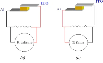
... 104 4.11 Experiments with 10KΩ external load.
Bibliography.
...
115
Appendices
...
120
A. Abbreviations ... 120 B. List of figures ... 122 C. List of tables ... 128
Chapter 1
Motivation - Outline.
1.1 Motivation.
To date, the primary source of energy is the combustion of fossil materials such as petroleum, coal or natural gases. The environmental impact of such combustion is dangerous for the planet so, over the past forty years, attempt has been made to discover new technologies and methods to use the power of the elements to produce viable energy. Until today the way to transform wind, water, but first of all solar energy into electrical or thermal energy has been studied. Useful devices apt to convert solar energy are photovoltaic cells, solar ovens and concentrators. In many populous regions of Earth, like Mediterranean area, it is possible to have, for 10 month out of about 12 free energy from the sun [1].
On the other hand, some attempts have been made to have free-pollution energy using biomass fuels, as in Brazil where 29-year-old ethanol fuel program [2] uses cheap sugar cane, mainly bagasse (cane-waste) for process heat and power, and modern equipment, and provides a ~22% ethanol blend used nationwide [3], plus 100% hydrous ethanol for four million cars [4].
Local minor low-pollution sources of energy could be considered geothermal energy and industrial or domestic waste biomass energy as biogas or waste fuels. In this PhD Thesis nuclear energy will be not taken into account as it is a free-pollution source, but we will consider only those energy conversion processes (eco-compatible or not)in which “co-products” of energy transformation are involved, for example such of combustion of fossil oil or bio-fuel, or radioactive slag [5]. The two focal items that convert an energy transformation process into an eco-compatible one are the time scale in which the “co-products” are absorbed
mechanisms or high temperature and high pressure reaction as occurs in the Earth mantel or core, and their impact on Earth life. As a consequence, the fossil oils or gases and radioactive material, are not renewable polluting materialsbecause the time scale of such regeneration is too long (about one hundred thousand years for fossil oil and several million year ex. for the uranium) and the effects on Heart life are lethal [6].
Until now several problems have come together, focusing on the global energy question; but the increase of the number of people that could access to the “energy” for industrial and domestic purpose is an urgent topic: population growth [7] and energy consumption are inexorably tied together (Fig. 1.1).
Thus our heritage to future generation should be a sustainable eco-compatible energy. The high price of oil and gas fossil materials, increasing during last year not only for political and economical purpose but mostly for the prevision of vanishing sources in few decades gives new impulse to free-pollution and suitable energy system production research but, on the other hand, allows the utilization of coil and natural gasses [8] (Fig.1.2 and 1.3) to increase.
Fig.1.2 Statistical estimation of global energy sources from 1980 to 2030.
The exploitation of energy sources involve a large earth pollution, accomplished by an increase of destructive phenomena for the earth ecosystem and dangerous for human life like CO2[9], NxOy [10], SO2 [10], tropospheric ozone [11], aromatic
compounds, toxic metal and compound fine-powders, emissions.
Population growth (Fig 1.3) associated to this badly “global energetic system” will produce unexpected negative effects on our planet and unpredictable consequences for our life.
Fig.1.3 Computer amplification of lights of NASA’s picture of the earth by night the
11th September of 2007 .
Energy consumers, for domestic or industrial purpose, are growing in quasi-exponential trend, because energy manage is strictly connected whit better life conditions. Wherever it is a really positive target especially in some “emerging” planet areas, the earth’s energetic resources used to date are not enough for all of us and the “such earth’s capacity” or “such renovation time” correlated to the existing energy conversion methods are insufficient.
1.2 The aim of the work
The object of this PhD. thesis work was development and characterization of novel thermal energy conversion devices, which could be used in large scale application as well as in small local applications for domestic or industrial purposes, where a thermal gradient could be available by sun or other sources. More precisely the main task of the researches has been to develop a novel organic thermovoltaic film and related devices. The adjective “thermovoltaic” it here used to define a devices very structural analogous to Photovoltaic devices, but being thermal energy converters instead of being photon energy converters. Since now thermal energy converters, generating electric power have been mainly defined as thermoelectric (TE) or thermionic (TI), or thermophotovoltaic (TPV) converters.
Thermoelectric materials work by selectively transmitting “hot” (high-energy) electrons from a warm reservoir to a cold reservoir, such that a thermal gradient can drive current flow against a bias voltage V, leading to power generation [12,13]. The major problem which needs to be solved, in these device applications, is to increase their efficiency, which is limited by the fact that thermoelectric materials establishes a direct thermal contact between the hot and the cold reservoir. This mechanism subtracts heat to the hot reservoir just to worm up the cold one. In recent years several authors have made many efforts to reduce this problem by planning special materials which would allow an easy conduction of the electron, preventing at the same time the heat conduction. In this contest it has been recognized that the exact form of the electronic density of states (DOS) in a thermoelectric material has a strong impact on the efficiency of power generation [14-17]. This is because, whereas each electron contributes the same energy eV to the power output, regardless of the electron’s initial energy, the efficiency is highest when the electrons that contribute to the current possess only the minimum thermal energy required to surmount the bias voltage. Electrons that leave the hot reservoir with an excess of thermal energy cool the hot reservoir more than necessary, reducing efficiency.
carefully engineer the electronic DOS [14,15,18,19], employing both band offsets and quantum confinement phenomena. Mahan and Sofo pointed out the advantage of delta-like singularities in the electronic DOS and suggested the use of narrow states in rare earth metals [20], and Hicks and Dresselhaus proposed that the reduced dimensionality of superlattices could be used to enhance the electronic density of states in energy ranges near the conduction band edge to improve the efficiency of power generation [12]. An additional advantage of the use of superlattices is the expected reduced thermal conductivity due to increased phonon scattering rates and phonon-localization, such that parasitic heat leaks can be reduced. Indeed, several authors have shown that thermal conductivity in superlattices is much lower than in pure bulk materials and can be lower than the
alloy limit[21-23]. The best performing thermoelectric materials demonstrated to
date are based on superlattices [24,25]. Heterostructured, low-dimensional materials are therefore thought to be the most promising candidate for broad, economical applications of thermoelectric power generation and heat recovery in the relatively near future, and considerable efforts are being expended to develop and characterize such materials.
A very original research idea, which has been tested in the frame of this thesis work, to improve thermoelectric devices, is to develop a new generation of thermovoltaic devices, by using plastic amorphous semiconductor film, instead of inorganic semiconductors. In this system, due to lack of an ordered lattice, phonon transmission is expected to be very low. On the other hand, work on
electrochromic devices conducted at Calabria University [26] has shown that a
certain amount of electron conduction can be obtained by inserting specially planned organic molecules in plastic matrices, where the electron conduction is obtained both by intermolecular electron excitations and intramolecular charge transfer jumps. The kind of device which realization was hypothesized at the beginning of this thesis is conceptually represented in Fig.1.4 and Fig.1.5.
Fig.1.4 Conceptual representation of the novel thermovoltaic device using a n-type film.
The scheme reported in the top, left side of the Fig. 1.4 shows (before contact) the work functions (black lines) of two different metal layers, and the HOMO, LUMO and Fermi level of an organic molecule (red lines). On the top, right side of Fig.1.4 the possible band configuration obtained after sandwiching the plastic layer of the organic molecule between layers of the two different metals, are shown in an open circuit configuration, and absence of heat flux (equilibrium configuration). The other two schemes reported in the bottom of Fig.1.4 represents an analogous situation where the second metal layer has an even lower electron extraction work. A blocking contact establishes especially between the higher work function metals and the organic molecule. The base hypothesis we worked with concerns the possibility to promote electron transfer between the highest work function metal to the lower work function metal, across the plastic film of the organic molecule, by using a thermal gradient, with the hot side applied on the left metal layer. The thermoelectric device obtained in this way is expected to have a good efficiency if the barrier created at the left metal /organic contact would not be to high with respect to KT energy at the temperature of the hot reservoir. In practice barriers greater than 0.1 Ev should be avoided (consider that KT is about 0.03 Ev at room temperatures).
In Fig. 1.4 the central film molecules are supposed to be n-doped. Analogous configuration can be represented in the case of a p-doped central film, as it is shown in Fig.1.5:
Fig.1.5 Conceptual representation of the novel thermovoltaic device using a p-type film.
Organic semiconductors become n-type or p-type as function of the nature of chemical substituents or dopants added to the molecular blend. As a general rule the presence of electron donor groups confers a n-type character to the semiconductor, while acceptor groups or dopants generates p-type semiconductors.
In a practical application the active molecules, having electronic levels compatible with he working strategy reported in Fig. 1.4, can be dissolved in a plastic supporting matrix having good mechanical, chemical and thermal properties. Of course such a blend of organic molecules would need to have a sufficient electrical conduction, in order to allow the electron transport from the hot to the cold side, and a low heat conduction in order to guarantee the establishing a the required temperature gradient, without transmitting to much heat from the hot to the cold reservoir.
It has been proved that semiconductor level of electronic currents can be obtained in plastic films by mixing π-conjugated organic oligomers such as poly-tiophenes, poly- vyniles, fullerenes, etc. These systems have been deeply investigated in photovoltaic devices where very tiny layers need to be applied.
Recently P.Reddy et al.[27] have studied the possibility to build up very small
thermoelectric devices, by using benzene-dithyol semiconductor molecules (BDT), sandwiched as very tin layers between two gold metal layers. We will come back on this device in chapter 4, where we use it for comparison. Nevertheless we believe that the idea to use these kind of molecules, as tin layer
semiconductors, in thermoelectric devices does not drive through a real technologic development of thermoelectric conversion , since the heat conduction across tin layers is very high When using plastic semiconductor films in thermoelectric conversion greater thickness of the central semiconductor film is required to avoid direct heat transfer between the hot and the cold reservoirs. For these reason greater specific electron conductivities need to be obtained in the central plastic layers with respect to those used in photo voltaic devices. Fortunately in our case we do not need to worry about electron /hole recombination, so the thickness of the central film can be increased at least up to values of millimetres.
It must be underlined that the thermoelectric plastic layer (or layers) should be blends of a supporting polymer , having good mechanical and chemical properties, with other electron carrier molecules. The supporting polymer matrix can be one of the very stable UV resistant polymer currently used in the manufacture of special glass (automotive front shield, bullet proof glasses) such as poly(vinyl butyral-co-vinyl alcohol-co-vinyl acetate) (PVB), poly(vinyl formal) (PVFM) etc. A limited percentage of these polymer is able to dissolve or disperse in a very homogeneous way big percentages of other molecules. The composite films can be obtained as self supported solid films which are easily laminated between other layers (the metal layers in our case), thus ensuring low cost manufacturing processes. Different kind of active electron carrier molecules can be dissolved in the supporting plastic matrix in order to get the desired LUMO levels (see Fig.1.4 and Fig.1.5) and the required conductivity. By taking into consideration the need of a sufficiently high electron conductivity the best
molecules to candidate as charge carriers into the plastic film should again be π
-conjugated organic oligomers such as poly-tiophenes, poly- vyniles, fullerenes etc., or blend of these compounds, but we will show in the next that these molecules do not posses the correct LUMO Levels. We will show in the next that the most encouraging results have been obtained by using blends of PVB and PVFM with bipyrimidinium salts.
Although the modern application of heat conversion in electric power seems to cover a niche market, it is obvious that thermal direct production of electric
energy has a very high potential both in large and small scale. How just mentioned above the use of organic materials should improve the device efficiency. In this case the application of low gradient working Thermoelectric devices, will become numerous: they could work a) during the night or in dark
conditions b) in cold as well in hot places (they need a ∆T, not an absolute
temperature value); and they could be useful in every condition when a thermal gradient is available (ex. sea or lake surfaces).
1.3 Outline
The sequence of the arguments exposed in this thesis work is given in the following.
In the second chapter a brief review of the principal renewable energy conversion systems will be presented, The principal devices on sales all over the world will be mentioned pondering both technologic and economic aspects, and linking positive features and hurdles for each energy conversion process.
Within the third chapter phenomenological laws that route fluxes conversions and stationary states will be mentioned underlining the transformations from heat flow to current. A detailed section will argue the chemical-physic concepts at the origin of the novel thermoelectric devices, and some efficiency parameters will be discussed..
In the fourth chapter novel organic thermovoltaic devices will be discussed, giving working and performance details, also relating phenomenological laws of energy conversion and charge mobility molecular mechanisms the experimental results are presented. Several experimental data have been collected, starting from preliminary experiments, which were carried out to observe an effective stationary state in our devices, to “step up” experiments using several materials and composition ratios. Appropriate experiments to improve and investigate the devices will be mentioned giving an idea of widespread materials applications. Also long-term experiment will be illustrated to evaluate the energetic, theoretical and technological aspects.
Chapter 2
Eco-compatible Energy conversion.
In order to highlight the scientific and practical importance to develop new efficient and low cost thermovoltaic devices, this chapter gives an overview of the most important technologies available to day for chemical, photon and thermal energy conversion.
2.1 Hydrogen and fuel cells
Hydrogen and fuel cells (FCs) [28] have the potential to solve relatively the dependence on petroleum imports, poor air quality, and greenhouse gas emissions (Fig. 2.1 a,b). FCs are electrochemical devices that convert the chemical energy of the fuel and oxidant directly into electricity and heat offering high efficiency, low emissions, modularity and quiet operation and they are a promising candidate for powering a wide range of applications, from portable electronics via vehicles to power stations. FCs generate electricity from a simple electrochemical reaction in which oxygen and hydrogen combine to form water. There are several different types of fuel cell but they are all based around a central design which consists of two electrodes, a negative anode and a positive cathode. These are separated by a solid or liquid electrolyte that carries electrically charged particles between the two electrodes. A catalyst, such as platinum, is often used to speed up the reactions at the electrodes.
(a)
(b)
Fig.2.1 Standard scheme of individual fuel cell (FC), H2 fuel and oxidant (oxygen)were used to generate electric power by electrochemical reactions (a), several FC typologies exist according the electrolyte and fuels used: (b) low temperature fuel cell PEMFC.
FCs are classified according to the nature of the electrolyte and each type requires particular materials and fuels and is suitable for different applications that imply the application in large or small scale: Proton Exchange Membrane Fuel Cells (PEMFC) used by NASA to provide power for the Gemini space project
producing 100W per module; Alkaline Fuel Cells (AFC) Alkaline fuel cells are one of the most developed technologies and have been used to provide power and drinking water to space missions, including the US Space Shuttle; Phosphoric Acid Fuel Cells (PAFC) is currently the most commercially advanced fuel cell technology: currently a number of working units with outputs ranging from 0.2-20MW installed around the world providing power to hospitals, schools and small power stations; Molten Carbonate Fuel Cells (MCFC) that works at too high temperature (650 °C) producing up to 2MW systems; Solid Oxide Fuel Cells (SOFC) work at even higher temperatures than molten carbonate cells (800-1000°C); Direct Methanol Fuel Cells (DMFC); is a variant of the PEMFC which uses methanol directly without prior reforming; Regenerative Fuel Cells (RFC) [29] technology works on the same basis as a conventional cell in that hydrogen and oxygen are used to generate electricity.
Otherwise, one more time, sun, wind and water represent the real effort to renewable energy conversion system (Fig 2.2) also using RFC technologies.
(b)
Fig.2.2 (a) Scheme of solar RFC cell in which electrolyser works to produce hydrogen
and oxygen in sun presence used by FC in sun and dark condition;(b)Scheme of a seasonal energy storage of PV-Hydrogen system.
The RFCs perform the electrolysis reverse reaction. The water generated in the fuel cell is fed to a solar powered electrolyser where it is separated into its constituent components of hydrogen and oxygen which are then fed back to the fuel cell. In this way a closed system is formed which does not require external hydrogen generation. The development of a commercial system is some way off and there are a number of issues that need to be addressed including cost and the perfecting of a reliable way of harnessing solar and wind power.
However when hydrogen is obtained from renewable energy sources, no global warming gases are emitted. Hydrogen fuel cell systems store intermittent solar and wind power so there is no need for back-up generators powered by fossil fuels.
2.2 Wind and Sun energy conversion systems.
To date the most common sources of renewable energy are wind [30] and sun. The first one could be a valid alternative to fossil fuels but the primary obstacle is represented by the high cost of power plant element. Intrinsic building costs of turbines associated with locating a accurate installation place, constantly winded places needed, mean that it is not for a domestic or local use: they need a lot of space considering the turbulence that occurs for each one element (both axial and longitudinal turbines). Otherwise wide use of wind power have to be encouraged by nations government in order to replace a lot of energy from combustion: at the end of 2006, worldwide capacity of wind-powered generators was 73.9 gigawatts; although it currently produces just over 1% of world-wide electricity use, it accounts for approximately 20% of electricity production in Denmark, 9% in Spain, and 7% in Germany. Globally, wind power generation more than quadrupled between 2000 and 2006 [31].
However in the direction of local purpose use (domestic and industrial) and wide range power plant installations, solar energy represent the best alternative to convert free energy in eco-compatible system.
To date the most efficient methods to “harvest” the sun energy are the “solar heating systems (SHS)”, “concentrating solar power systems (CSP)” and the “photovoltaic systems (PV)”; lees developed methods are “thermophotovoltaic (TPV)”, “thermionic (TI)” and “thermoelectric (TE)” energy conversion systems, that represent the next future generation techniques.
SHS [32] harvest the power of the sun to provide solar thermal energy for solar hot water and solar space heating by solar thermal collectors: flat-plate or evacuate tube collectors, adsorbing plates, parabolic collectors and sun-tracking plates are just some example of large literature and patents existing. Also they have some kind of storage system, except solar pool heaters and some industrial systems that use energy “immediately”, collecting directly the sun’s energy to heat air or a fluid.
Large-scale solar thermal technology is known as CSP [33] (Fig 2.3). This research and development focuses on three types of concentrating solar
technologies are used in CSP plants that use different kinds of mirror configurations to convert the sun's energy into high-temperature heat.
(a) (b)
Fig.2.3 The 11 MWatt CSP plant is located in Seville, Spain have the capacity to
produce sufficient energy to let some 180,000 homes consume power from it (a) and the 64MWatt in California, USA Creek (b).
The heat energy is then usually used to generate electricity in a steam generator, but is it also possible to use TI, TPV or TE devices as shown in the apposite sections in this chapter.
Photovoltaic devices (PV) can be made from various types of semiconductor materials, deposited or arranged in various structures, to produce solar cells that have optimal performance to convert sun light in electrical current. A PVc is the basic building block of a PV (or solar electric) system. An individual PVc is usually quite small, typically producing about 1 or 2 watts of power. To boost the power output of PVcs, they were connected together to form larger units called modules. Modules, in turn, can be connected to form even larger units called arrays (Fig. 2.4), which can be interconnected to produce more power, and so on. In this way, we can build PV systems able to meet almost any electric power need, whether small or large.
Fig.2.4 Photovoltaic cell, module and array.
By themselves, modules or arrays do not represent an entire PV system. We also need structures that point them toward the sun, and components that take the direct-current electricity produced by modules and “condition” that electricity, usually by converting it to alternate-current electricity. We might also want to store some electricity, usually in batteries or to electrical typical network, for later use. All these items are referred to as the “balance of system” (BOS) components. Combining modules with the BOS components creates an entire PV system.
2.2.1 Inorganic photovoltaic cell (IPVc).
In its simplest form, the PVc [34] consists of a junction formed between n-type and p-type semiconductors, either of the same material (homojunction) or different materials (heterojunction) (Fig 2.5).
Fig.2.5 Sun light effect on silicon(p-n) photovoltaic cell: the incident light produce a
charge separation and a direct current.
The unique possible free electrons motion is regulated by the inner electric field generates when n- and p- type semiconductor were assembled together. In fact when the two joined semiconductors have different work functions (Fig 2.6 a,b), electrons are driven off from the highest work function electrode that became the positive pole and, passing throw the device, they are collected at the interface near to the lowest work function electrode that became the negative pole [35]. In other words the two semiconductors reach the same Fermi level value.
(a)
(b)
Fig.2.6 Energetic representation of p-n semiconductors bandgap (a) in isolate
p and n type, (b) when junction occurs and Fermi level achieved..
However an inner electric field at semiconductors/electrode interfaces are generated and the system is in equilibrium state. At the p-n interface, the sunlight induces a charge separation that drives free electrons into n-type semiconductor and a electrons depleting (the “holes”) into p-type one. This charges, moving across the bulk according the inner electric field, produce a direct current (Fig.
Fig.2.7 Energetic representation of p-n semiconductors bandgap when separation
charge was induced by light photons.
If an external load is connected in series with device, a current passes through the load in order to re-establish the equilibrium condition. Obviously electron flow does not occur when no more photons irradiate the device, instead the system works in a stationary state in witch the radiation energy is converted in current. By far the most common material for solar cells is crystalline silicon [36] and these cells can be divided into a number of categories (Tab 2.1): “Monocrystalline wafers” are the most efficient of the PV technologies in good light conditions. However, since they are cut from cylindrical ingots the cells are normally pseudo-square and cannot completely cover a module without a substantial waste of space. This makes them more expensive than other technologies; “Poly or multi crystalline cells” are made from cast ingots - large crucibles of molten silicon carefully cooled and solidified. These cells are cheaper than single crystal cells and used to be less efficient but steady developments in PV technology are now delivering comparable performance. They can easily be formed into square shapes that cover a greater percentage of a panel than monocrystalline cells; “Thin film approaches” are module-based. The entire module substrate is coated with the desired layers and a laser scribe is then used to delineate individual cells. Thin film PV is efficient in low light conditions and very sturdy; “Inorganic hybrid
cells” are a combination of monocrystalline and thin-film technologies, this has high peak output coupled with excellent performance in poor light conditions [37].
Tab.2.1Some characteristic values of the four main different types of silicon PVc.
However many doped semiconductor alloys could be used to built more efficiency IPVcs like gallium arsenide, gallium seleniure, copper indium diselenide or gallium indium phosphate (25% of module efficiency for monocrystalline GaAs
and 30% for GaInP/GaAs device) [38]. Whenever intrinsic costs are so high that their application are for scientific purpose like space research.
2.2.2 Organic photovoltaic cell (OPVc).
Considerably less effort and production energy is necessary if organic semiconductors are used because of simpler processing at much lower temperatures (20-200 °C) than the above mentioned inorganic cells. For example an electro-chemical solar cells using tanium dioxide in conjunction with an organic dye and a liquid electrolyte (ex. the Graetzel dye-sensitized cells) already exceeded 6% power conversion efficiencies and are about to enter the commercial market thanks to their relatively low production costs [39]. The organic photovoltaic cells could be divided into tree main groups: the organic-electrolytic dye sensitized solar cell (DSSC), the fully organic semiconductor polymers cell (POPVc) and the most recent organic/inorganic hybrid cell (HOPVc).
Dye sensitized solar cells (DSSc).
The dye sensitized solar cell (DSSc) [40] is conceptually the nearest nature-like photovoltaic device (considering for example the leafs) and is composed of one metal cathode and one transparent conductor (mostly a conducting oxide on glass), onto one of which a few μm thick film of wide band gap semiconductor has been deposited in the form of a self-connected network of 3nm-sized particles, with a network of similarly (or large sized self-connected pores) between the particles. Energy conversion in a DSSC (Fig. 2.8) is based on the injection of an electron from a photoexcited state of the sensitizer dye (typically a bipyridine metal complex) into the conduction band of the nanocrystalline semiconductor (TiO2 is by far the most employed oxide semiconductor). These cells also employ a liquid electrolyte usually an iodide/triiodide redox-active couple dissolved in an organic solvent to reduce the dye cation and to regenerate the ground state of the dye. Regeneration of iodide ions, which are oxidized in this reaction to triiodide, is achieved at a platinized counter electrode (S: represents the dye sensitizer):
Fig.2.8 Energetic representation of dye sensitized solar cell.
At conducting glass (ex. ITO) electrode:
TiO2|S + hv TiO2|S*
TiO2|S* TiO2|S+ + e
-At chatode (ex. Aluminum or gold electrode):
1/2 I3- + e- 3/2 I
-Fig.2.9 Nanometric TiO2 dye absorption increases dye active surface.
The TiO2 nanoparticles was used also to increase the dye surface and to improve
the photon absorption efficiency (Fig 2.9), thus as the depletion surface results larger than single layer device one as well the electron transfer probability between electrolyte molecules and dye was increased.
Organic semiconductor polymers cell (POPVc).
An interesting alternative respect the inorganic cells is given by the semiconductor polymers [41], which combine the optoelectronic properties of conventional semiconductors with the excellent mechanical and processing properties of polymeric “plastic” materials. These can be processed from solution at room-temperature onto flexible substrates using simple and therefore cheaper deposition methods like spin or blade coating. Since the discovery of electro-luminescence in conjugated polymers, this class of materials has been used to build efficient light emitting diodes, field effect transistors, optically-pumped LASERs and photovoltaic diodes.
The advantage of POPVcs when compared to electro-chemical cells is predominantly the absence of a liquid electrolyte, which generates problems with sealing against air, but also the prospect of even cheaper production using large area devices and the use of flexible substrates.
To date several approaches to organic photovoltaic active composites have been investigated. These include strategies based on photo-induced charge transfer between layers of low molecular weight organic molecules (LMW), within halogen-doped organic single crystals, within single component molecular dyes, between conjugated polymers and polymer blends, and within a single-layer blend of a conjugated polymer and an LMW molecule.
Compared with research efforts devoted to small-molecules organic materials, the polymeric photovoltaic materials (and especially donor/apceptor “bulk heterojunction composite”) represent a relatively recent approach to exploiting photoinduced charge transfer phenomena for solar energy conversion considering both the small molecules and the conjugate polymer as classical semiconductors. Interest in conducting and photovoltaic properties of conjugated polymers like polyacetylene, various derivates of polythiophenes (PT) and poly(phenylenevinylenes) (PPV) developed. Instead using of inorganic semiconductor in which electron mobility occurs rapidly after photoinduced charge transfer, the idea of using photoinduced charged state in organic semiconductor class, in conjunction with a molecular electron acceptor to achieve charge separation, is based on the stability of photoinduced exitations such “positive polarons, negative polarons or polarons-excitons” on the conjugated polymer backbone. Motivating results were found in a cell composed by mixtures
or bilayers of conjugated polymers with fullerenes (C60)[42]. This devices show
in solid organic films an ultrafast (subpicosecond) and reversible photoinduced
Fig.2.10 Energetic scheme of C60-conjugated polymer system during photonic exitation .
The first photovoltaic devices based on this photoinduced electron transfer were diodes consisting of bilayers from conjugated polymers and fullerene, showing low photovoltaic power conversion efficencies due to the small charge generating interface. However functionalized fullerenes were synthesized in order to increase the C60 group solubility and to produce highly fullerene-loaded composite films. Power conversion efficency made from poly[2-methoxy-5-(2'-ethyl-hexyloxy)-1,4-phenylenevinylene] (MEH-PPV)/fullerene composite was subsequently increased by two order of magnitude and many conjugated polymers were
investigated[43]: transpolyacetilene, polythiophene (PT), polycarbazole (PCBZ),
polyisothianaphtalene, polyaniline (PAN) etc.
To date exist four different architectures for OPVc: single layer cells, blend cells,
double layer cells, laminated devices.
Single layer structures consist of only one semiconductor material and are often referred to as Schottky type devices or Schottky diodes since charge separation occurs at the rectifying (Schottky) junction with one electrode. The other electrode interface is supposed to be of ohmic nature. The structure is simple but absorption covering the entire visible range is rare using a single type of molecule.
The photoactive region is often very thin and since both positive and negative photoexcited charges travel through the same material recombination losses are generally high.
The Schottky barrier [44] is usually defined the energetic barrier when heterojunction occurs. The Schottky barrier is present to silicon inorganic photovoltaic cells but more relevant effect were noticed when organic compounds are put in contact with metal electrodes. Also it is possible to define when an organic material produce a ohmnic or not ohmnic contact considering the HOMO-LUMO organic semiconductor levels, metal electrodes work function and energy Fermi level after heterojunction occurs (Fig. 2.11 a, b, c, d or also Fig.1.4 and
Fig. 1.5).
(a) (b)
(c) (d)
Fig.2.11 Energy band diagrams of donor D and acceptor A materials devices. a),b) the
situation before contact; c),d) after contact the Fermi levels (dashed lines) and work function equalize and band bending occurs. (b) The formation of a blocking contact for holes (ITO/D) and electrons (A/Al). (d) The formation of a non-blocking (ohmnic) contact for holes (Au/D) and electrons (A/Ca).
The strong point of blend cell [45] typology is the large interface area if the molecular mixing occurs on a scale that allows good contact between alike molecules (charge percolation) and most excitons to reach the donor/acceptor interface. This can usually only be partly achieved so the defects of the network structure, particularly the connectivity with the correct electrode, represents a technological challenge.
The double layer cells [46] benefit from the separated charge transport layers that
ensure connectivity with the correct electrode and give the separated charge carriers only little chance to recombine with its counterpart. The drawback is the small interface that allows only excitons of a thin layer to reach it and get dissociated.
Laminated devices [47] represent the successful attempt to unify the advantages
of the two structures above. Charge separation occurs in the blend layer in the middle that is obtained after laminating the two separate layers together and charge transport can only occur via the correct transport layer. This structure also features the useful options to treat each layer separately (ex. doping, physical/chemical conversion) before form ing the blend layer and instant encapsulation between the two substrates. The drawback is that certain mechanical properties of the organic semiconductors are required (low glass transition temperature) to form the intermixed layer. Since a donor can act as an acceptor for an even stronger donor because these two terms can not really be used separately, there are certain functionalities that are likely to make a material an electron acceptor with respect to most other materials. Examples for
functionalities that favour electron acceptor properties are: -CN, -CF3, -F, = O
(keto-groups) or diimides (all perylenederivatives in this thesis are perylene diimides). These groups are known as electron withdrawing groups if they are attached to an unsaturated (conjugated) system. Note that their ability to enhance the electron affinity of the entire molecule is not purely connected to the electron withdrawing properties of these functionalities. It is essentially a result of both the
inductive and the mesomeric effect. The average of possible π electron locations
can be regarded as the overall mesomeric effect of a specific molecular structure.
perylene diimides. Most organic semiconductors behave more like electron
donors, for example PPV, PT, PPP and phthalocyanines. Examples for large π
systems are phthalocyanines, naphthalocyanines and perylenes.
The bandgap can also be small if a molecule consists of a donor and an electron acceptor that are connected via a conjugated structure to create a “push/pull system” as in poly-methines. Such structures can accomplish charge transfer sometimes in the ground state (ex. charge transfer salt) or only little extra (light) energy is required to complete it. Examples for charge transfer salts are PVK-TNF [48] , merocyanines and 4,4’ bipyrimidinium (viologens) salts [49].
Solubility is good if the planar parts of the conjugated π systems of the molecules
can not get too close to each other. Otherwise they would stick together, driven by their π− π interaction, to form aggregates for example larger clusters particles which do not contain solvent. Flexible and bulky side chains or atoms that stick out of the molecular plane can prevent molecules from getting to close.
In most organic device only a small portion of the incident light is absorbed for several reasons. One of these is that semiconductor bandgap is too high: a bandgap of 1.1eV (1100nm) is required to absorb 77% of the solar radiation on earth whereas the majority of semiconductor polymers have bandgaps higher than 2.0eV (600nm) limiting the possible absorption to about 30% [50]. Further the typically low charge carrier and exciton mobilities require layer thickness in the order of 100nm. Fortunately the absorption co efficient of organic materials is generally much higher than in silicon so that only about 100nm are necessary to absorb between 60 and 90% if a reflective back contact is used. In addiction reflection losses are probably significant but little investigated in these materials and anti-reflection coatings as used in inorganic devices may then prove useful once other losses such as recombination become less dominant. But the strong points are the exciton diffusion, the charge separation and charge transport in
organic semiconductors [51]. Ideally, all photoexcited excitons should reach a
dissociation site. Since such a site may be at the other end of the semiconductor, their diffusion length should be at least equal the required layer thickness for sufficient absorption, otherwise they recombine and photons were wasted. Exciton diffusion ranges in polymers and pigments are typically around 10nm. However,
some pigments like perylenes are believed to have exciton diffusion lengths of several 100nm. Charge separation is known to occur at organic semiconductor/metal interfaces, impurities (ex. oxygen) or between materials with sufficiently different electron affinities (EA) and ionisation potentials (PI). Than one material can act as electron acceptor A while the other keeps the positive charge and is referred to as electron donor D since it did actually donate the electron to A. If the difference in IA and EA is not sufficient, the exciton may just hop onto the material with the lower bandgap without splitting up its charges. Eventually it will recombine without contributing charges to the photocurrent. The transport of charges is affected by recombination during the journey to the electrodes, particularly if the same material, serves as transport medium for both electrons and holes. Also, interaction with atoms or other charges may slow down the travel speed and thereby limit the current. In order to enter an electrode material with a relatively low absolute values of work function (ex. Al, Ca) the charges often have to overcome the potential barrier of a thin oxide layer. In addition, the metal may have formed a blocking contact with the semiconductor so that they can not immediately reach the metal.
For organic semiconductor (as well as in metallic as inorganic semiconductor materials) the molecular order influence absolutely the transport of electrons (and
holes)[52]. Thus to keep an high conduction in organic material thin organic solid
films or polymeric ordered structure were usually investigated (Fig. 2.12). However some conjugate polymer shows conductivity similar to silicon semiconductor material.
Fig.2.12 Electrical conductivity of conjugated polymers related to insulator, semiconductor an metal materials.
Organic/inorganic hybrid cell (HOPVc).
Recent results have demonstrated that HOPVcs based on a blend of inorganic
nanocrystals [50] (n-type semiconductor) and polymers (p-type semiconductor)
possess significant potential for low-cost, scalable solar power conversion acquiring ordered structures and increasing the PVc charge transport and efficiency. Colloidal semiconductor nanocrystals [53], dispersed in polymers, are solution processable and chemically synthesized, but possess the advantageous properties of inorganic semiconductors such as a broad spectral absorption range and high carrier mobilities. Significant advances in hybrid solar cells have followed the development of elongated nanocrystal rods and branched
nanocrystals [54], which enable more effective charge transport. The
incorporation of these larger nanostructures into polymers has required optimization of blend morphology using solvent mixtures. Future advances will rely on new nanocrystals, such as cadmium telluride tetrapods, that have the potential to enhance light absorption and further improve charge transport. Gains can also be made by incorporating application-specific organic components, including electroactive surfactants which control the physical and electronic interactions between nanocrystals and polymer. Although experimental printed
PVcs are far less efficient than the solid-state variety. The best results were obtained using tiny rods of cadmium selenide (7 nm in diameter and 60 nm long) solid semiconductor and poly-3-hexylthiophene (P3HT) organic polymer [55]. The technique is still highly experimental, but the hybrid cells produced worked well under low light converting the 6.9% of the sunlight energy (only the 1.6% considering the simulated full solar spectra experiments). Main problem is that the polymer and solid are in such close contact that electrons “and holes” can reach the wrong conductor, nullifying the electrical current. A suggestion could be to add some blocking layers to the cells or using different length or orientation of the rods to capture more light, but it rises production costs, such as in more sophisticated and expensive cells, like the ones just bolted onto the Hubble Space Telescope, use more than one light-absorbing semiconductors, and thus can grab light more efficiently. A suitable alternative at CdSe nanorods/polythiophene cell could be the ZnO crystalline nanoparticles and coniugate polymer like
poly[2-methoxy-5-(3',7'-dimethyloctyloxy)-1,4-phenylene vinylene] (MDMO-PPV)[55]
(Fig 2.13).
This device typology could uses nanoparticles instead the nanostructure (like nanorods) reducing production costs without no important efficiency decrease, considering that better results were obtained using ZnO nanorods made via wet
chemical procedure and aligned perpendicular to electrode surface[56] (Fig 2.14).
Fig.2.14 ZnO nanorods perpendicular to electrode surface.
Novel strategy to design nanowire functionalized electrodes are studying with much larger areas available for dye adsorption. It is worth noting that the advantages of the nanowire geometry are even more convincing for other types of PVc, such as inorganic-polymer hybrid devices in which an oriented continuous and crystalline inorganic phase could greatly improve charge collection.
2.3 Costs and limitations of PVc.
While in most organic device only a small portion of the incident light is absorbed for the explained reason in previous paragraph, several researchers believe that organic devices represent the future. In fact whenever just a little region of solar spectra is used in light conversion (Fig. 2.15) low production cost of devices and their wide-range use, according their mechanical properties, make the OPVc a full interest devices.
Fig.2.15 Sea level solar spectra (black line) compared with two OPVcs: P3HT-PCBM
film blu line; MDMO-PPV-PCMB film red line .
Thus while the perspectives are to see low cost and high efficiency organic cell into several years, to date (Fig. 2.16) the largest used photovoltaic material, balancing costs and efficiencies, result the Silicon[57].
However Silicon PV technologies has an high cost due to intrinsic raw material costs and high temperature production processes: considering a four members family living in the south of Italy to have a suitable PV system (about 3 KWatt)
about 23000 euros and 30 m2 of free surface need. Than, it is possible to have an
idea of the 1 MWatt power plant installation costs. However PVcs do not produce energy during the night and the power plant or family installations should be connected in a general network suitable to supply at the energy vacancies by conventional methodologies (ex. fossil fuels) or some other renewable sources (ex. wind). Obviously, considering this kind of devices and infrastructure, the PV systems could not replace the use of conventional energy sources, but just should reduce their utilizations.
Fig.2.16 Commercial PV module efficiencies were compared with PV best laboratory
result .
The unique (and ahead of its time) idea to supply at fossil fuels combustion should be to create a “global photovoltaic network” (as network existing to date for petroleum or fossil gas) to connect solar power plant in different world regions: the exceeded power supply in daylight regions could be used to night time regions during the day and vice versa during the night. Alternatively accumulators, batteries or fuel cells costs should be added to power plant cost.
2.4 State of art of solar thermal energy conversion (TPV, TI, TE).
Moreover a brief distinction between the “solar heating systems (SHS)”, “concentrating solar power systems (CSP)” described in the apposite section
above and the thermophotovoltaic (TPV) [58]”, “thermionic (TI) [59]” and
“thermoelectric (TE)” energy conversion systems mentioned in this section and in next chapter 3 need. Basically the SHS and CSP apply the sun heat to warm up fluids that could be used to produce electrical energy, while TVP, TI or TE materials convert the sun radiation directly in current. Moreover it is possible to
link up the CSP system (concentrating the sun power) with TVP,TI or TE materials.
In the following three section a brief overview of state of the art of TI, TPV and TE devices is designed, subsequently in the next chapter 3 theoretical aspects, deductions and applications will be pointed out .
Thermionic devices (TI).
In a thermionic converter [59], heat energy is converted to electrical energy by
thermionic emission, whereby electrons are emitted from the surface of certain metals when the metals are sufficiently heated. The three major components of a basic thermionic energy converter are the thermionic emitter, the collector, and the working fluid, which may be vacuum or an electron gas or a partially ionized
plasma (Fig.2.17). The input heat, Qin, heats the emitter, and electrons are emitted.
The cold collector receives some of these electrons at an output heat, Qout. The
difference (Qin -Qout) is the energy that drives the electrons through the external
circuit, and appears as electrical energy. The collector is cooled to remove the output heat. Electrons in metal have a temperature dependent energy distribution. If the temperature of Metal 1 (the emitter) is increased, eventually some electrons can have sufficient energy to overcome the surface potential barrier called the
work function 1, which ordinarily prevents electrons from leaving the surface.
In this process, shown by solid lines on the energy diagram, electrons accumulate
a potential = 2 – 1, which can be used to drive electric current through the
external load R, when the circuit is closed. There also is a reverse or back current of electrons shown by dashed arrows on the energy diagram, which competes with forward current. Typically this current is minimized by the larger work function of the Metal 2, 2, and its lower temperature that produces fewer energetic
electrons. The minimum known work function is about 1.1 electron-Volts (eV). Vacuum converters, which have electron gas as their operating fluid, operate in
the range 1200°K to 1400°K. They typically produce 1 W/cm2 at an efficiency of
5 percent. Low-pressure converters produce 10 W/cm2 at an efficiency of 10
deliver 40 W/cm 2 at an efficiency of 20 percent, operating at emitter temperatures up to 2200°K. In laboratory conditions, efficiencies as high as 40% are reported.
Fig.2.17 Thermionic vacuum converter simplify scheme and energy diagram of the two
metal work functions Φ1 (the emitter) and Φ2 (the collector).
Obviously the principal applications of TI energy converters are in regions not easily accessible such as the outer space (using sun energy) or the undersea areas (using fuel combustion) or the polar regions (using appropriate solar collector system or fuel combustion). But The two important heat sources for TI device persist in the sun and nuclear reactors.
Direct thermal to electrical energy conversion systems that could operate at relatively lower temperatures (300-650°C) with high efficiencies (>15-20%) provide an attractive compact alternative to internal combustion engines for many applications in the W-MW range.
Materials design for these purpose is focused on increasing the efficiency of heterostructure TI power generators using embedded quantum dot (QD) structures and metal/semiconductor superlattices [60]: thermal diodes have the same functional components as TI converters but with a semiconductor wafer substituted for the vacuum gap (Fig 2.18).
Fig.2.18 Thermal semiconductor wafer diodes scheme.
Manufacturing a thermal diode starts with a thermoelectric semiconductor wafer (gap) on which a thin barrier layer is deposited. The barrier layer is made of the same semiconductor, but doped differently. The deposited emitter layer is a heavily doped layer of the same semiconductor or a metal. The collector structure is basically the same two layers as on the hot side. Potential barriers at the interfaces between emitter and barrier layers and barrier layer and gap serve the same purpose as the work function in a TI converter (Fig. 2.17).
For relatively low voltages, there are more high-energy electrons on the hot side of the barrier, and power is generated by a net electron flow from the hot to the cold reservoirs. If the voltage is increased, the number of high-energy electrons on the cold side of the barrier increases.
By changing dopant concentration these potential barriers can be adjusted and optimized for any temperature. The first barrier on the emitter layer side sorts electrons by energy and the second barrier on the gap side prevents back flow of electrons from the gap into the emitter layer. Without potential barriers, the output of this device will be defined by the thermoelectric properties of the gap material (see the TE section below). Barrier action leads to accumulation of electric charge behind the barrier, leading to increased operating voltage. The electric resistance of the device is dominated by the macroscopic gap with very little change from its thermoelectric value, leading to current increase due to increased voltage compared with the thermoelectric performance of the semiconductor gap. The highest experimentally observed internal efficiency of a thermal diode is 88% of Carnot Efficiency, which is competitive with any existing energy converter.
However to convert sun power using the TI device sun power concentrator CSP and a efficient heat reservoir or cooling system need to warm up the emitter material and cooling the collector.
Thermophotovoltaic devices (TPV).
A generic TPV system [61] consists of a source of heat (a flame, radiative isotope, the sun, etc), a radiator, a semiconductor converter, a means of recirculating the sub-bandgap photons to conserve system energy, and a power conditioning system (Fig. 2.19).
Fig.2.19 A Generic TPV system simplified scheme.
Early work on TPV converters focused mainly on silicon and germanium converters (Fig, 2.20). However, the quality of these elemental semiconductors was poor. It is the impressive progress in novel devices that has led to the high performance of modern TPV devices and the consequent interest in this field. Most, but not all, recent device work has concerned the semiconductors GaInAs and GaInAsSb grown by organo-metallic vapor-phase epitaxy (OMVPE), or molecular beam epitaxy (MBE).
Fig.2.20 A silicon TPV generator with 20KW methane burner that achieved a maximum
The radiator may be either broad or narrow band. If the former is used, then the spectral emittance must be as close to unity as possible and the material most commonly used has been silicon carbide. This has an emittance of about 0,9 emettance units, and it will withstand temperatures up to approximately 1900 K [62]. Optimization of the bandgap depends, as expected, on the radiator temperature and there is inevitably a large proportion of the incident photons that have of too low energy to be absorbed. For the overall system to have an acceptably high efficiency, these must be returned to the radiator to be re-absorbed using the filters. Narrow-band radiators considered to date include ytterbia, erbia, holmia and neodymia. These radiate at energies of approximately 1.1, 0.7, 0.6 and 0.5 eV respectively. Modelling of TPV systems, using broad-band radiators and design experience, suggests that energy conversion efficiencies of 15% may be achievable in the short-term but a longer-term effort would be required to reach 20%.
In solar thermophotovoltaic (STPV) systems, that represent the real renewable energy source utilization of TPV, thermal radiation resulted from the emitter (radiator) material heated up to high temperature by the concentrated sunlight is converted into the electric power by means of photocells sensitive to the IR part of spectrum. The forbidden gap and the structure of a STPV cell can be correlated for conversion of a particular radiation spectrum at definite temperature. In a STPV system, differently from conventional solar cells, application of selective filters is practicable, which reflects the radiation unused by a photocell back to the emitter. This allows to rise the emitter temperature and offers promise for increasing the total efficiency of a solar thermophotovoltaic system.
The use of the concentrated sunlight as a heat source to a TPV [63] system instead of a burning fuel is promising for increasing the TPV conversion efficiency with retaining all advantages of the sunlight converters.
Owing to that at the TPV conversion a radiation source can be located very close to a photocell, and also due to creation of high-effective photoconverters and emitters matched with them by spectrum the achievement of electrical power of
2-10 W/cm2 is made possible. Thus, the actually achievable specific power output
kW hour/cm2 per year (Fig 2.21), which exceeds in several hundreds times the
average specific power output from the terrestrial solar arrays. It should be noted that the specific amount of electric power generated by the photoconverter unit area of a TPV generator in 100-200 times higher than in solar arrays.
A significant economical effect, but not ecological one, due to higher efficiency and life expectancy, will be ensured by application of TPV generators instead of electromechanical ones (based on the internal-combustion engine).
Supplying of a high sunlight concentration, changing the radiation spectrum of an emitter of photons, filtering the radiation to return unused photons and to reduce the heat action on photocells and assembling photocells into tandems allowing to increase the emitter radiation photovoltaic conversion efficiency, represent the problems could be arise to optimize STPV generators.
Fig.2.21 Dual concentrator of the sunlight CSP applied on TPV device. It consists of a
Fresnel lens(PMMA made) and a secondary lens of a quartz glass. 90% of the concentrated beam energy is focused in a 10 mm spot. This concentration system ensures the concentration ratio of 3600x. A special benefit of the system is its low cost.
Two TPV modules are under development: cylindrical and conical. In general case, a photon emitter made of a refractory metal is placed in a quartz chamber
filled with a rare gas (Ar or Xe) to prevent oxidation. In the conical system, the thermal radiation is reflected by a conical shape mirror covered with gold, and photocells are mounted on a plane base. In the cylindrical type module, photocells are mounted on the internal side of the cylindrical base being cooled and surround the emitter of a cylinder form (Fig. 1.22).
(a) (b)
Fig.2.22 A tantalum emitter (a) installed in a STPV module of cylindrical type(b).
Both modules were tested in outdoor conditions at the direct solar radiation. At measured direct sunlight power of 800-850 W/m2 the emitter temperature in
cylindrical module was obtained in the range of 1400-1900K, depending on the emitter size and material. In a conical module, at the emitter temperature of near 2000K, the photocurrent density of 4.5 A/cm2 and the voltage of 0.49V were measured for a GaSb photocell [63].
Thermoelectric devices (TE).
In 1822-23, around the same time that Sadi Carnot was studying the limiting efficiency of the steam engine, Thomas Seebeck described in the Journal of the Prussian Academy of Sciences a discovery he called “the magnetic polarisation of
metals and ores produced by a temperature difference”. Seebeck was interested in
this phenomena as supposed evidence in support of his belief that the existence of the earths magnetic field could be explained in terms of the temperature difference between the equator and the polar ice cap. However it is clear that what Seebeck
actually discovered was the existence of an electrical current in a closed circuit made up of different conductors in which the junctions of the materials are held at different temperatures. Theoretical aspect will be specially illustrated in the next chapter 3.
The real significance of the discovery was in the potential to generate power from low-grade heat. Had Seebeck developed a device to produce electricity using the best materials he found (ZnSb and PbS), he might have made a heat engine with an efficiency of ≈ 3%, equal to the best steam engines of his time.
In contrast to the thermoelectric devices (TE), in thermionic devices (TI) electron transport is ballistic: the distance electrons must travel between the hot and cold reservoirs is less than the mean-free path between. A discrete TI system (Fig
2.23a) consisting of two electron reservoirs with different temperatures and
electrochemical potentials [59]. A continuous TE system (Fig 2.23b) consisting of a conductor in which electrons are subject to an opposing electrochemical potential and temperature gradient [64].
(a) (b) Fig.2.23 A discrete TI system (a). A continuous TE system (b).
TE devices are also generally made by creating two junctions of n- and p-type
semiconductor materials where a thermal gradient is imposed [64,65] (Fig.2.24)
and the TE modules (like PV ones) are composed by several TE cells having really small size (from several µm2 to several cm2 surface) (Fig. 2.25).