PAPER • OPEN ACCESS
Numerical and experimental study on metamaterials featuring acoustical
and thermal properties
To cite this article: Elisa Levi et al 2020 J. Phys.: Conf. Ser. 1599 012032
View the article online for updates and enhancements.
Numerical and experimental study on metamaterials featuring
acoustical and thermal properties
Elisa Levi, Manuela Neri, Mariagrazia Pilotelli*, Edoardo Alessio Piana and Adriano Maria Lezzi
Università degli Studi di Brescia, via Branze 38, 25123 Brescia (Italy) * e-mail: [email protected]
Abstract. Metamaterials can be defined as materials which, for their peculiar composition or
structure, exhibit characteristics that are not normally found in nature. “Multifunctional” metamaterials could be used to optimise different characteristics at the same time. In this paper the authors try to apply them for thermal and acoustic optimization of external building walls. Thermal optimization consists in obtaining a low transmittance, important in winter, and a low periodic thermal transmittance, important in summer. Acoustic optimization consists in obtaining high sound transmission loss, to respect the law prescriptions, and a good sound absorption coefficient, if possible. In this way should be possible enhance the comfort conditions in buildings and reduce the energy demand for winter heating and summer cooling. The proposed solution consists of several layers with different suitable characteristics: the sequence of the layers has been chosen with particular care. The thermal analysis has been performed by means of a self-developed code based on the ISO 13786 standard. The acoustic behaviour of the single layers has been determined following the procedure given by the ASTM E2611-09 standard using a four-microphone impedance tube and the transfer matrix method has been used for the complete assembly. This preliminary combined study showed encouraging results.
1. Introduction
1.1. Literature analysis
The European directive 2010/31/UE on the energy performance of buildings [1] states that edifices account for 40% of total energy consumption in the European Union (EU). Therefore, taking into account outdoor and indoor climatic conditions, the energy performance of buildings must be enhanced. As a consequence, all the EU member states will have to take the required actions to guarantee that some minimum requirements on the energy performance are satisfied, for building units or building elements constituting the building envelope. The requirements must be met by all the elements having a significant impact on the energy performance of the building, every time they are replaced or retrofitted. The limits must be set with the purpose of achieving cost-optimised results [2]. The study of alternative solutions such as phase-change materials, able to fulfil winter and summer requirements, see for instance [3], is of broad and current interest as well.
With the introduction of Ministerial Decree (DM) 26 June 2015 [4], the European directive 2010/31/UE has come into force also in Italy. This regulation categorises the type of building renovations distinguishing among “major first-level renovations”, “major second-level renovations”
2
and “energy upgrading interventions”. The revamps concerning building envelope elements with an impact on the overall area above 25% are defined “major renovations”. “Major first-level renovations” are those involving the building envelope with an incidence higher than 50% of its overall area, the renovation of the heating system and/or the cooling system of the whole building. In these cases, the energy performance requirements are applied to the whole building. Renovations involving the building envelope for more than the 25% of the overall area of the building, affecting the heating system and/or the cooling system, are defined “major second-level renovations”. In the cases discussed so far, the energy performance demand refers to the thermo-physical features of the building portions and to the extents of the building envelope elements involved in the renovation. Finally, “energy upgrading interventions” are all the other types of interventions having an impact on the energy performance of the building. This type of interventions involve an extent that is below or equal to 25% of the total area of the building, and/or encompass the heating and/or cooling system. In such cases, the energy performance requirements only apply to the involved building components and installations. The DM 26 June 2015 defines also the requirements for the different cases.
As concerns the opaque vertical envelope components of the existing buildings undergoing renovation – which are the object of this work – in case of major first-level renovations the overall heat transfer transmission coefficient value H'T has to fulfil a limit value between 0.48 W/(m2 K) and 0.80 W/(m2
K) depending on the
surface to volume ratio
S/V and on the climate zone, being the zones defined by the Presidential Decree 26 August 1993, n. 412 [5] in terms of degree-days and of heating periods and number of hours per day; moreover, for sites where the value of the average monthly irradiance on the horizontal plane during the month of highest summer insolation is greater than or equal to 290 W/m2, it is required that the value of the mass per unit area Ms is greater than 230 kg/m2, or that the
value of the periodic thermal transmittance Yie is lower than 0.10 W/(m2 K) for all the opaque vertical
walls excluding those included in the northwest / north / northeast quadrant. In the event of major second-level renovations, the value of the overall heat transfer transmission coefficient H'T has to
respect the limit values of 0.73 W/(m2 K) for the climatic zones A and B, 0.70 W/(m2 K) for the
climate zone C, 0.68 W/(m2 K) for the climate zone D, 0.65 W/(m2 K) for the climate zone E and 0.62
W/(m2 K) for the climate zone F; moreover, the thermal transmittance U must fulfil the limit values,
which are going to become stricter starting from 2021 (0.40 W/(m2 K) for the climate zones A and B, 0.36 W/(m2 K) for the climate zone C, 0.32 W/(m2 K) for the climate zone D, 0.28 W/(m2 K) for the
climate zone E and 0.26 W/(m2 K) for the climate zone F). For energy upgrading interventions, only the limit values of the thermal transmittance U must be respected.
It should be noted that in 2018 was published the Directive 2018/844 of the European Parliament and of the Council [6]. It amends Directive 2010/31/EU on the energy performance of buildings and Directive 2012/27/EU on energy efficiency with the aim of accelerating the improvement of energy efficiency by integrating various aspects. Moreover it focuses to buildings with higher comfort levels and wellbeing for their occupants, according to the 2009 World Health Organisation guidelines. Just in these days, with Decree Presidency of the Italian Republic (DPR) n. 48 [7], it has also been implemented in Italy.
1.2. Background models
Thermal coatings are often applied to improve the energy performance of existing buildings. They consist of an insulating layer applied to the external surface of the wall. They are generally more efficient than internal insulation systems because they significantly reduce the thermal bridges. Thermal coatings are usually studied so to improve thermal insulation, but they can also improve summer thermal behaviour when allow to significantly reduce and delay the transmission inside the
building of the highest temperature reached on its outer surface during the central hours of the day. For the above-mentioned reasons, in this paper some explanations are made considering both the effect of the transmittance U and of the periodic thermal transmittance Yie. As concerns the thermal
transmittance U, the estimated values have been compared with those proposed in the cases of major second-level renovations and of energy upgrading interventions. For the periodic thermal transmittance Yie a reference value of 0.10 W/(m2 K) has been considered in the case of major
first-level renovations.
For a sandwich wall, the thermal transmittance U depends upon the characteristics of the composing layers, while the periodic thermal transmittance Yie also depends on the arrangement of the layers. The
thermal conductivity λ and the thermal capacity C are the most influencing material properties. The insulation of the building is described by the thermal transmittance U and can be determined by using an electrical analogy for steady heat transfer conditions. The periodic thermal transmittance Yie
represents the dynamic performance of the partition and is particularly relevant for summer performances. The dynamic thermal characteristics of a building component define its thermal behaviour when it is subject to variable boundary conditions of heat flow rate or temperature.
According to the ISO 6946 [8] standard, for a steady condition, the thermal transmittance U of a multilayer partition is defined as U = (Rs1 + R1 + R2 + … + RN + Rs2)-1, where R1, R2, …, RN are the
thermal conductive resistances of the single layers. The conductive resistance of a layer is defined as the ratio between the thickness and the thermal conductivity. The terms Rs1, Rs2 are the surface
resistances of the boundary layers, and they include convection and radiation.
In summertime, heat flux and temperature vary over time. The ISO 13786 [9] is the reference standard to calculate the thermal properties of a building element in periodic conditions: it considers only time-dependent sinusoidal boundary conditions and walls made of homogeneous layers. To evaluate the performance of the building element in unsteady conditions, the periodic thermal transmittance Yie and
the thermal admittance are defined. The periodic thermal transmittance Yie is a complex number that
correlates heat flux rate to cyclic variation of the temperature. Differently from U, the periodic thermal transmittance Yie depends also on the layer distribution and their thermal capacity C. The thermal
admittance correlates the specific heat flux to the temperature variation on the same side of the wall. The periodic thermal transmittance correlates the heat flux on a side to the temperature variation on the opposite side of the wall. The periodic thermal transmittance is defined as Yie = – q''i/Te, where Te
is a sinusoidal function and Ti is considered constant. The internal thermal admittance is defined as Yii
= q''i/Ti, where Ti is a sinusoidal function and Te is considered constant, the external thermal
admittance is defined as Yee = q''e/Te, where Te is a sinusoidal function and Ti is considered constant.
These three terms, Yii, Yee, Yie, can be determined from the heat transfer matrix Zee = Zse ∙ Z ∙ Zsi. The
terms Zse and Zsi are the heat transfer matrices of the boundary layers and they take into account both
convection and radiation. According to the ISO 6946 standard they are defined as
(1)
According to the ISO 13786 standard, Z is the transfer matrix of a multi-layer component from surface to surface
(2)
The calculation of Z consists of several steps. First of all, for each layer, the following terms are calculated
4 (3) (4) (5)
where d is the thickness of the layer, λ is its thermal conductivity and δ is its periodic penetration depth computed as δ = [86400 × λ / (π × C)]1/2 for a period of 24 h. For each i-th layer, these terms are
combined to calculate the heat transfer matrix:
(6)
The heat transfer matrix Z of the entire wall is calculated by combining the heat transfer matrix of all the layers as Z = ZN ∙ ZN – 1 ∙ … ∙ Z3 ∙ Z2 ∙ Z1 where, as a convention, layer 1 is the innermost layer.
The periodic thermal transmittance Yie is determined from the elements of the heat transfer matrix
from environment to environment Zee as Yie = - (1/Zee12).
For inhomogeneous layers, where inhomogeneity is due to thermal bridges, the ISO 6946 and ISO 13786 are the references standards again, but the method described above is no longer applicable. The influence of such thermal bridges can be estimated through analytical and neural methods as proposed by [10, 11, 12].
The acoustic characterization of materials is based on the evaluation of two main parameters: the sound absorption coefficient α, which describes the capability of the material to dissipate sound energy, and the sound transmission loss TL, which expresses the sound insulation attitude and is closely connected to the sound transmission coefficient τ by means of the formula TL = 10 log10(1/τ).
The impedance tube, which consists in a double standing wave tube mounted with four microphones, allows to experimentally estimate the acoustic properties. The main strengths of this measurement technique lie in that it requires to use only small samples and it provides additional useful properties, such as the characteristic impedance, the propagation wavenumber and the speed of sound inside the sample. On the other hand, it provides information on the material behaviour only with normal sound incidence. Coupling the use of impedance tube with the transfer matrix method, it is possible to build the correlation between the state variables on the front (subscript 0) and back (subscript d) sides of the sample with respect to the position of the sound source:
(7)
where p and u are, respectively, the sound pressure and the particle velocity, and Θij are the transfer
matrix elements.
When dealing with multi-layered structures, it proves to be a particularly valuable method for acoustic characterisation and optimisation, since the relative acoustic properties derive from the total transfer matrix, which is obtained as the product of the transfer matrices of each layer in the proper order [13]:
(8)
In case of materials comparable to equivalent fluid, namely those whose shear modulus is negligible [14], the transmission loss TL estimated from measurements in impedance tube can be considered
independent of boundary conditions. Otherwise, in case of solid-elastic material, such as rigid panel, it is more convenient to write the transfer matrix as follows:
(9)
Here, the acoustic impedance of the material, Zp, incorporates the actual boundary conditions obtained
from direct measurements, and it is calculated as Zp = jωμ × [1 – (1 + jη) × (f/fc) × sin2 ϑ], where µ is
the mass per unit area of the panel, η is the loss factor, fc is the critical frequency, that is defined for a
homogeneous plate as fc = c2 × (2π)–1 × (μ/Dp)1/2. Dp is the bending stiffness per unit width, which can
be estimated through vibro-acoustic tests or point mobility measurements.
2. Materials and methods
From the thermal point of view, the wall thermal transmittance U and the periodic thermal transmittance Yie have been calculated as explained in the subsection 1.2. “Background models”.
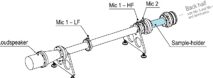
According to the standard procedure ASTM E2611 [15], the four-microphone impedance tube (Figure 1) is composed in this way: a loudspeaker is mounted at the source endpoint and generates the noise test signal, in this case a wide-band white noise. The second endpoint of the tube is closed by either hard-backed termination or anechoic termination, so to have two different boundary conditions, which is necessary when testing geometrically asymmetrical specimens. The central section of the tube is equipped with a test sample holder in which the specimen is located, between two microphone pairs.
Figure 1. Schematic drawing of a four-microphone impedance tube.
Referring to Figure 1, it is possible to compare signals from four microphones and subsequently decompose the acoustic wave field among forward and backward travelling waves on each side of the specimen. The four components A, B, C, D indicate the incident and reflective fractions and, computed through the following correlations provided by standard ASTM E2611, allow to establish the transfer matrix elements. The absorption coefficient α (reflective backed) can be expressed as:
(10)
and the sound transmission loss TL (anechoic backed) is obtained as:
(11)
where ρ is the air density, c is the speed of sound, k is the wavenumber in air, defined as k = 2πf / c. Two segments of length 1200 mm constitute the custom-made impedance tube with 45 mm internal diameter. Such cross-section maintains valid the plane-wave assumption up to about 3800 Hz. A 100 mm loudspeaker is located at the source endpoint in a sealed and isolated volume, while a rigid reflective termination or an anechoic termination closes the second endpoint. The microphone spacing
6
is 45 mm for high-frequency measurements and 500 mm for low-frequency measurements. A separate segment of tube of proper length is used as sample holder, installed in the central section of the apparatus, between the microphone pairs. In Figure 2 the model of the tube is shown. A multichannel analyser generates the test signal and measures the complex transfer functions between the microphones, housed in O-ring-equipped ports. Temperature and atmospheric pressure are considered, so to correct the speed of sound and the air density values during the post-processing.
A self-built code, based on the ASTM E2611 standard procedure, has been used to post-process the measured transfer functions and obtain the acoustic behaviour of the specimen through its acoustic parameters, namely the sound absorption coefficient, the sound transmission loss, the characteristic acoustic impedance, the propagation wavenumber and the speed of sound in the material.
To perform the thermal-acoustic analysis, a wall characterised by poor thermal performances has been considered, and possible thermal improvements have initially been investigated. The bare wall is made of 200 mm-thick hollow bricks, a configuration called P0 in Table 1. The first improved configuration, P1, includes an additional external 80 mm-thick layer made of wood fibre, characterised by a density of 140 kg/m3. The second configuration, P2, consists in two layers of wood fibre: the first layer is
80 mm thick and its density is 110 kg/m3, and the external layer is 40 mm thick and its density is 265 kg/m3. The third solution, P3, consists of a 50 mm-thick layer made of aerogel having density of 180
kg/m3.
Figure 2. Portion of the tube including the loudspeaker. LF = low frequency; HF = high frequency.
The aerogel panels are obtained through nanotechnological processes combining amorphous silica aerogel and high density reinforcing mineral fibres. Therefore, they can be considered metamaterials providing tunable thermal performance and easy to use, as shown by other authors who selected aerogel to obtain compact soft materials with improved acoustic properties [16]. Considerations on the economic impact and lifetime of aerogels is beyond the scopes of this paper. However, they should be carefully taken into account in practical evaluations as the cost of the material is generally high compared to traditional solutions and the durability strongly depends on the selection of the product [17]. The metamaterial nature of the structures investigated in this work is strengthened by the presence of more layers with different thermophysical properties and performing different functions. The thermal optimisation has been carried out first, then the acoustic properties of the thermally optimised structures have been predicted through the transfer matrix method.
3. Results
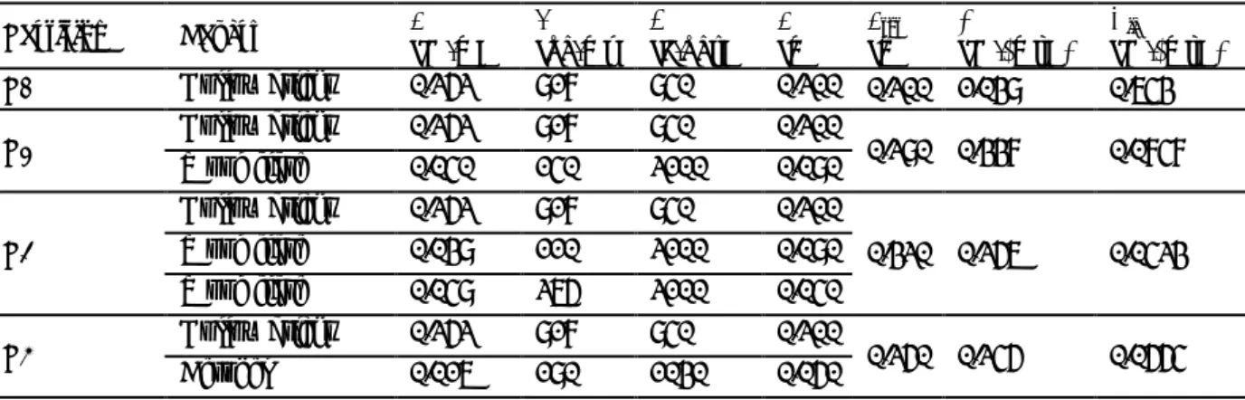
The thermal performances of the bare wall P0 and of the three proposed multilayer partitions are summarised in Table 1. It can be noted that all three solutions allow to significantly reduce both the transmittance and the periodic thermal transmittance of the wall. In particular, by comparing the transmittance values obtained with the limits prescribed in Italy by the DM 26 June 2015 for vertical
walls involved in building renovation by the year 2021, it can be noted that both partition P2 and partition P3 could be used in all the Italian climate zones. Indeed, their transmittances are below the limit value of 0.26 W/(m2 K) for the climate zone F. On the other hand, partition P1 could only be
used in the climate zones A, B and C, since its transmittance is less than 0.36 W/(m2 K). Concerning
the periodic thermal transmittance, partition P2 has the lowest value, thus ensuring the best summer behaviour. However, all three solutions ensure a good summer behaviour since their periodic thermal transmittance values are below 0.1 W/(m2 K). Partition P3 could therefore be considered the best
choice, given that it has the minimum value of both transmittance and thickness.
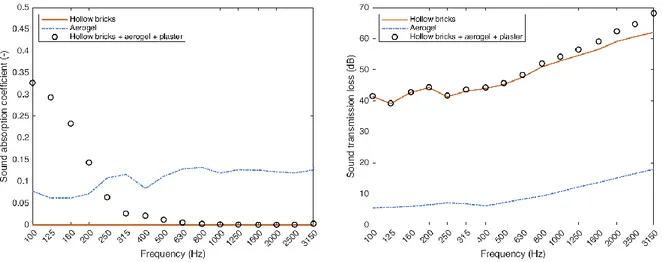
After the first selection based on thermal evaluation, the acoustic characterisation of partition P3 has been performed. In particular, the hollow brick sound transmission loss has been derived from sound transmission suites measurement, whereas a sample of thickness 50 mm of aerogel has been tested in impedance tube. The acoustic performances of the multilayer partition have been then determined with the transfer matrix method: it is worth noting that the presence of the finishing plaster layer, negligible for the thermal behaviour of the partitions, has a significant influence on the acoustic absorption behaviour. It is worth noting that the sound absorption coefficient of the hollow bricks wall (red line in Figure 3a) is null for the entire frequency range of interest. Therefore, partition P3 includes in this case a 10 mm-thick layer of external plaster in addition to the other two layers. The results are reported in Figure 3. It can be observed that the aerogel layer and the plaster slightly improve the sound insulation in the low frequency range, whereas the improvement is considerable above 2 kHz. This is due to the multi-layered nature of the partition. The single number sound reduction index, Rw, for the considered
wall increased from 51 dB to 52 dB.
Table 1. Thermal performances of the bare wall P0 and of the multilayer partitions P1, P2 and P3. Partition Layers λ [W/mK] ρ [kg/m³] c [J/kg·K] d [m] dtot[m] U [W/(m²K)] Yie [W/(m²K)]
P0 Hollow bricks 0.252 817 840 0.200 0.200 1.038 0.643
P1 Hollow bricks Wood fibre 0.252 0.040 817 140 840 2100 0.200 0.080 0.280 0.337 0.0747
P2
Hollow bricks 0.252 817 840 0.200
0.320 0.256 0.0423
Wood fibre 0.038 110 2100 0.080
Wood fibre 0.048 265 2100 0.040
P3 Hollow bricks Aerogel 0.252 0.016 817 180 840 1030 0.200 0.050 0.250 0.245 0.0554 4. Conclusions
This research work aims to design new solutions to enhance at the same time different aspects of existing masonry buildings, also through the use or design of appropriate metamaterials. In particular, this paper illustrates a preliminary evaluation of three multilayer partitions designed to improve the acoustic and thermal performances of masonry walls. The thermal properties, transmittance and periodic thermal transmittance, have been determined according to the standard ISO 13786. The thermally best-performing wall among the investigated ones, which has the lowest values of transmittance and thickness, consists of standard hollow bricks and aerogel layers. The addition of an aerogel layer is shown to be a potential solution to improve the thermal performance of the wall, especially when cost is not an issue and high-durability products are selected. Finally, the transfer matrix method allowed to estimate the acoustic performances of the whole partition, which provides a good improvement of the sound absorption coefficient especially if the aerogel is exposed to the sound
8
field. The addition of a plaster layer, necessary to protect the aerogel, improves the sound absorption in the low frequency range adding a “panel resonance” effect but deteriorates this feature in the mid-high frequency range. This behaviour can be improved by using a sound absorbing plaster to safeguard the aerogel from extreme weather conditions. As concerns the sound transmission loss, the performances are slightly improved only in the mid-high frequency range because the aerogel do not add a significant mass to the overall weight of the wall.
Figure 3. Acoustics performances of aerogel and bare wall P0 (measured) and of the multilayer
partition P3 (predicted): sound absorption coefficient (right) and sound transmission loss (left).
Acknowledgements
The authors would like to thank Ecofine S.r.l. for providing the Aerogel samples used in the tests. The study has been funded by the Department of Mechanical and Industrial Engineering - University of Brescia, in the framework of the project PRD-METATER.
REFERENCES
[1] European Parliament 2010 2010/31/EU Directive of the European Parliament and of the Council on the energy performance of buildings (EPBD recast)
[2] Tronchin, L, Fabbri K and Tommasino M C 2014 On the Cost-Optimal Levels of Energy-Performance Requirements for Buildings: A Case Study with Economic Evaluation in Italy,
International Journal of Sustainable Energy Planning and Management 3, 49, DOI:
10.5278/ijsepm.2014.3.5
[3] Neri, M, Ferrari P, Luscietti D and Pilotelli M 2020 Computational Analysis of the Influence of PCMs on Building Performance in Summer, Advances in Intelligent Systems and Computing
982, 3. DOI: 10.1007/978-3-030-19756-8_1
[4] Italian Ministry of Economic Development 2015 DM 26 giugno 2015 “Applicazione delle metodologie di calcolo delle prestazioni energetiche e definizione delle prescrizioni e dei requisiti minimi degli edifici.”, Supplement to the Official Gazette of the Italian Republic,
162. In Italian
[5] Presidency of the Italian Republic 1993 DPR 26 August 1993 n. 412 “Regolamento recante norme per la progettazione, l'installazione, l'esercizio e la manutenzione degli impianti termici degli edifici ai fini del contenimento dei consumi di energia, in attuazione dell'art. 4, comma 4, della legge 9 gennaio 1991, n. 10”, Supplement to the Official Gazette of the Italian Republic,
[6] European Parliament 2018 Directive (EU) 2018/844 of the European Parliament and of the Council of 30 May 2018 amending Directive 2010/31/EU on the energy performance of buildings and Directive 2012/27/EU on energy efficiency
[7] Presidency of the Italian Republic 2020 DPR 10 giugno 2020 n. 48 “Attuazione della direttiva (UE) 2018/844 del Parlamento europeo e del Consiglio, del 30 maggio 2018, che modifica la direttiva 2010/31/UE sulla prestazione energetica nell'edilizia e la direttiva 2012/27/UE sull'efficienza energetica.”, Official Gazette of the Italian Republic, 146. In Italian
[8] ISO (International Organization for Standardization) 2017 ISO 6946 Building components and building elements – Thermal resistance and thermal transmittance – Calculation methods [9] ISO (International Organization for Standardization) 2017 ISO 13786 Thermal performance of
building components – Dynamic thermal characteristics – Calculation methods
[10] Tenpierik, M, van Der Spoel W and Cauberg H 2008 An Analytical Model for Calculating Thermal Bridge Effects in High Performance Building Enclosure, J Build Phys 31 (4), 361, DOI: 10.1177/1744259107088008
[11] Luscietti D, Gervasio P and Lezzi A M 2014 Computation of linear transmittance of thermal bridges in precast concrete sandwich panels, J Phys Conf Ser 547 (1), no. 012014, DOI: 10.1088/1742-6596/547/1/012014
[12] Benedetti M, Gervasio P, Luscietti D, Pilotelli M and Lezzi A M 2019 Point Thermal Transmittance of Rib Intersections in Concrete Sandwich Wall Panels, Heat Transfer Eng 40 (13-14), 1075, DOI: 10.1080/01457632.2018.1457208
[13] Lee, C.-M., Xu, Y. 2009 A modified Transfer Matrix Method for prediction of transmission loss of multilayer acoustic materials, J. Sound Vib., 326 (1-2), 290, DOI: 10.1016/j.jsv.2009.04.037 [14] Feng, L. 2013 Modified impedance tube measurements and energy dissipation inside absorptive
materials, Appl. Acoust., 74 (12) 1480, DOI: 10.1016/j.apacoust.2013.06.013
[15] ASTM (American Society for Testing and Materials) 2010 ASTM E2611 Standard Test Method for Normal Incidence Determination of Porous Material Acoustical Properties Based on the Transfer Matrix Method, West Conshohocken, Pennsylvania, US
[16] Guild M D, Garcia-Chocano V M, Sanchez-Dehesa J, Martin T P, Calvo D C and Orris G J 2016 Point Thermal Transmittance of Rib Intersections in Concrete Sandwich Wall Panels,
Phys. Rev. Applied 5, 034012, DOI: 10.1103/PhysRevApplied.5.034012
[17] Chal B, Foray G, Yrieix B, Masenelli-Varlot K, Roiban L and Chenal J-M 2018 Durability of silica aerogels dedicated to superinsulation measured under hygrothermal conditions,