Ricerca Sistema Elettrico Sigla di identificazione ADPFISS – LP1 - 126 Rev. 0 Distrib. L Pag. di 2 41
Index
Index ... 2 Index of Figures ... 3 Index of Tables ... 4 1 Introduction ... 52 PERSEO facility description ... 6
3 Initial conditions and quasi-steady-operation of PERSEO facility ... 12
4 Description of Test 7 ... 14 4.1 Test 7 Part 1 ... 15 4.2 Test 7 Part 2 ... 27 5 Conclusion... 38 Abbreviations ... 39 References ... 40
Ricerca Sistema Elettrico Sigla di identificazione ADPFISS – LP1 - 126 Rev. 0 Distrib. L Pag. di 3 41
Index of Figures
Figure 2-1: PERSEO facility scheme [2] ... 6
Figure 2-2 Flow diagram of PERSEO facility [1]... 8
Figure 2-3 Location of the temperature measurements in the Heat Exchanger Pool (HXP) [1] .... 9
Figure 2-4 Location of the temperature measurements in the Overall Pool (OP) [1] ... 10
Figure 3-1: Power trend as function of the pool water level and operating pressure ... 13
Figure 4-1: TEST 7 PART 1 - Primary side pressure ... 19
Figure 4-2: TEST 7 PART 1 - HX pool and overall pool level ... 19
Figure 4-3: TEST 7 PART 1 - HX exchanged power ... 20
Figure 4-4: TEST 7 PART 1 - Steam and condensate flow rate ... 20
Figure 4-5: TEST 7 PART 1 - HX pool temperatures (level 1) ... 21
Figure 4-6: TEST 7 PART 1 - HX pool temperatures (level 2) ... 21
Figure 4-7: TEST 7 PART 1 - HX pool temperatures (level 3) ... 22
Figure 4-8: TEST 7 PART 1 - HX pool temperatures (level 4) ... 22
Figure 4-9: TEST 7 PART 1 - HX pool temperatures (level 5) ... 23
Figure 4-10: TEST 7 PART 1 - HX pool temperatures (level 6) ... 23
Figure 4-11: TEST 7 PART 1 - HX pool temperatures (level 7) ... 24
Figure 4-12: TEST 7 PART 1 - HX pool temperatures (level 8) ... 24
Figure 4-13: TEST 7 PART 1 - HX pool relative pressure ... 25
Figure 4-14: TEST 7 PART 1 - Overall pool temperatures ... 25
Figure 4-15: TEST 7 PART 1 - HX upper and lower headers wall temperature ... 26
Figure 4-16: TEST 7 PART 2 - Primary side pressure ... 30
Figure 4-17: TEST 7 PART 2 - HX pool and overall pool water level ... 30
Figure 4-18: TEST 7 PART 2 - HX exchanged power ... 31
Figure 4-19: TEST 7 PART 2 - Steam and condensate flowrate ... 31
Figure 4-20: TEST 7 PART 2 - HX pool temperatures (level 1) ... 32
Figure 4-21: TEST 7 PART 2 - HX pool temperatures (level 2) ... 32
Figure 4-22: TEST 7 PART 2 - HX pool temperatures (level 3) ... 33
Figure 4-23: TEST 7 PART 2 - HX pool temperatures (level 4) ... 33
Figure 4-24: TEST 7 PART 2 - HX pool temperatures (level 5) ... 34
Figure 4-25: TEST 7 PART 2 - HX pool temperatures (level 6) ... 34
Ricerca Sistema Elettrico Sigla di identificazione ADPFISS – LP1 - 126 Rev. 0 Distrib. L Pag. di 4 41
Figure 4-27: TEST 7 PART 2 - HX pool temperatures (level 8) ... 35
Figure 4-28: TEST 7 PART 2 - HX pool relative pressure ... 36
Figure 4-29: TEST 7 PART 2 - Overall pool temperatures ... 36
Figure 4-30: TEST 7 PART 2 - Heat exchanger upper and lower headers wall temperature ... 37
Index of Tables
Table 2-1: PERSEO main components material ... 11Table 3-1: Test 7 Part 2 quasi steady operation condition (1500 s – 2000 s) ... 13
Table 4-1: Test 7 Part 1 valve events timing [1] ... 18
Table 4-2: Main Relevant thermal hydraulic aspect related to the Test 7 Part 1 [1] ... 18
Table 4-3: Test 7 Part 2 valve events timing [1] ... 29
Ricerca Sistema Elettrico Sigla di identificazione ADPFISS – LP1 - 126 Rev. 0 Distrib. L Pag. di 5 41
1 Introduction
This report contains the description of Test 7 Part 1 and 2 performed on PERSEO facility. PERSEO is a full scale facility aimed at studying a new passive decay heat removal system operating in natural circulation. It was built at SIET laboratories in Piacenza (Italy) modifying the existing PANTHERS IC-PCC facility [1]. The operating parameters are characteristic of a generic BWR type reactor or the secondary side of a generic PWR type reactor, avoiding valve on the primary circuit. PERSEO equipment was not designed to simulate a specific passive system of a particular reactor (as it happened in SPES and PANTHERS facilities, for example). Its main purpose is the assessment of the performance and the efficiency of a new in-pool heat exchanger for decay heat removal, implementing natural circulation. The facility was conceived as an evolution of a previous CEA-ENEA proposal (thermal valve device [2][3]) which moved the SBWR-IC activation valve from the high pressure primary side to the low pressure pool side. In this system proposal, it has been changed the modality to start the operation of the system (now the HX pool starts empty) and therefore it has been changed also the size of the pool. Therefore the facility well represents the physical phenomena in a real time scale.
The main innovation in PERSEO facility is the presence of two pools connected by a line with a triggering valve. In this way it is possible to fill the pool where the heat exchanger is located only when it is needed for safety reasons, by using the water stored in a second separate pool that could be placed also outside the containment (in this case it should be also verified that the pressure drop in the steam line connecting the HXP and the OP does not limit excessively the natural circulation between the two pools).
PERSEO experimental campaign was carried out at SIET in October and November 2002. Five shake-down tests were performed to characterize the main parameters of the facility and to verify the correct functioning of all the equipment. After that, four full tests were done in order to characterize the thermal hydraulic behavior and the operation/performance of the proposed design at different conditions, during a generic transient progression, and the related stability. Among the four actual tests performed, Test 7 has been chosen for the benchmark exercise for its completeness. The test is at full pressure (70 bar) and it is aimed to verify both the system stability with different water pool levels and the long term cooling capability of the system. The test is divided into two parts, both described in this report addressing the stability and the long term test. The aim of this document is to highlight the thermal-hydraulic phenomena observed in Test 7 Part 1 and 2.
Ricerca Sistema Elettrico Sigla di identificazione ADPFISS – LP1 - 126 Rev. 0 Distrib. L Pag. di 6 41
2 PERSEO facility description
The PERSEO test facility was built by modifying the existing PANTHERS IC-PCC facility considering the new passive system proposal and its requirements. The scheme of the PERSEO facility is depicted in Figure 2-1.
Figure 2-1: PERSEO facility scheme [2]
The main components of PERSEO facility are: The pressure vessel (43 m3
volume and 13 m height);
The steam line from the pressure vessel to the HX upper header; The condensate line from the HX lower header to the pressure vessel;
The Heat Exchanger (composed of two cylindrical headers and 120 vertical straight pipes); The new Heat Exchanger Pool HXP (29 m3
volume and 5.7 m height). The area of the HXP is an important dimension for reproducing the expected prototypical physical-behaviour of the proposed system. A 5.04 m2 area was used, permitting prototype time-behaviour and sufficient steam/water separation at the top of pool [3][4];
Ricerca Sistema Elettrico Sigla di identificazione ADPFISS – LP1 - 126 Rev. 0 Distrib. L Pag. di 7 41
The Overall Pool OP (173 m3
volume and 5.8 m height). In this pool the old PANTHERS PCC heat exchangers are still present but not used in these tests;
The line connecting the OP and the HXP with the triggering valve; The steam duct connecting the two pools.
The pressure vessel is the multipurpose GEST facility, available at SIET [5]; it is used to maintain the saturation condition typical of a generic BWR or of the secondary side of a generic PWR in the in-tube side of PERSEO facility. Considering the general application of the system, the in-vessel circuit of PERSEO does not have any direct scaling relation with any BWR and PWR prototypical pressure drop circuit.
The pressure can be controlled by regulating the steam supply received from a nearby power plant (EDIPOWER power Station). At the beginning of the test the HX, the feed line and the drain line are full of saturated steam; the HXP is full of air or steam depending on the test; the OP is full of cold water at the nominal level and the triggering valve is closed. To start the desired test, the triggering valve is opened and the heat exchanger pool is flooded by cold water and the heat transfer takes place from the heat exchanger to the pool. As soon as pool water boiling starts, the steam produced in the heat exchanger pool is driven to the overall pool through the steam duct. The injector contributes to mix the water in the OP, thus limiting temperature stratification within the pool. When steam starts to be produced in the OP, it is vented to the atmosphere through the boil-off pipe. When the injector is uncovered, no condensation is present anymore in the overall pool and the steam flows outside directly through the boil-off pipe. In some tests, water is drained from the overall pool to accelerate the transient phase with water level decreasing [1][2]. Figure 2-2 shows the flow diagram of PERSEO facility and Table 2-1 the materials of the main components. Figure 2-3 shows the location of the temperature measurements in the Heat Exchanger Pool (HXP) and Figure 2-4 the location of the temperature measurements in the Overall Pool (OP).
Ricerca Sistema Elettrico Sigla di identificazione ADPFISS – LP1 - 126 Rev. 0 Distrib. L Pag. di 8 41
Ricerca Sistema Elettrico Sigla di identificazione ADPFISS – LP1 - 126 Rev. 0 Distrib. L Pag. di 9 41
Ricerca Sistema Elettrico Sigla di identificazione ADPFISS – LP1 - 126 Rev. 0 Distrib. L Pag. di 10 41
Ricerca Sistema Elettrico Sigla di identificazione ADPFISS – LP1 - 126 Rev. 0 Distrib. L Pag. di 11 41
Table 2-1: PERSEO main components material
Component Material
Heat exchanger Inconel-600
Condensate drain line in pool Stainless steel 316 Condensate drain line out of pool Carbon steel
Steam line Carbon steel
Steam line vertical final part (after T-A004) Stainless steel 316 + Rockwool + Stainless steel 316
Steam line tubes to upper header Stainless steel 316
Pools connection line Carbon steel
HX pool Stainless steel 304 and outer reinforcement
structure in carbon steel
Overall pool Fiberglass
Steam duct Fiberglass
Injector Stainless steel 316
Ricerca Sistema Elettrico Sigla di identificazione ADPFISS – LP1 - 126 Rev. 0 Distrib. L Pag. di 12 41
3 Initial conditions and quasi-steady-operation of PERSEO facility
The initial conditions of Test 7 do not represent a classical steady-state conditions that can be used to assess the nodalization in steady-condition. In fact, the initial conditions of the facility represent the thermal hydraulic condition of the prototypical passive system not in operation with the PV in a stable pressure condition.In this condition the system is in the following configuration:
HXP with a fixed water level and the remaining volume filled with air (in Test 7 Part 1) or steam (in Test 7 Part 2);
OP filled with water;
Pressure vessel in saturation conditions at 70 bar;
No mass flow rate in the steam duct connecting the two pools; No mass flow rate in the line connecting the HXP and the OP;
Negligible power exchanged in the HX and therefore no fluid circulation in the pressure vessel circuit.
Since the main target of the prototypical system is to remove the residual power, the key figure of merit to consider, characterizing the system, is the power removed from the HX, which clearly will depend on the pressure vessel saturation condition and on the level in the HXP (Figure 3-1). Therefore, during the Tests 7 the power removed from the system, as a function of the level, is investigated. In the Figure 3-1 tendency lines, obtained with a moving average filter, are shown.
For Test 7 Part 2 it is possible to identify in the central part of the transients a quasi-steady-condition. In this temporal window it is possible to compute mean values of the parameters measured in the facility; this quasi-steady-conditions is between 1500 s and 2000 s. Table 3-1 presents the average, minimum and maximum flow rate, pressure and pressure drop values for this time window.
Ricerca Sistema Elettrico Sigla di identificazione ADPFISS – LP1 - 126 Rev. 0 Distrib. L Pag. di 13 41
Figure 3-1: Power trend as function of the pool water level and operating pressure
Table 3-1: Test 7 Part 2 quasi steady operation condition (1500 s – 2000 s)
Experimental parameter Mean
value
Maximum value
Minimum value
Flowrate steam supply line (F_A001) [kg/s] 13.18 13.31 12.96
Flowrate condensate drain line (F_E001) [kg/s] 12.80 13.34 12.17
Power heat exchanger (W_IC) [MW] 20.10 20.85 19.08
Diff. pressure vessel outlet – HX inlet (DP-001) [kPa] 6.10 6.62 5.58 Diff. pressure HX inlet – upper header (DP-002) [kPa] 14.33 14.83 13.77 Diff. pressure HX upper header – lower header (DP-003) [kPa] -1.20 -1.01 -1.39 Diff. pressure HX lower header – drain line (DP-004) [kPa] -8.60 -7.22 -9.84 Diff. pressure drain line 1 (DP-006) [kPa] -11.78 -10.68 -12.87
Diff. pressure drain line 2 (DP-008) [kPa] -4.97 -2.96 -6.66
Diff. pressure drain line 3 (DP-011) [kPa] -38.87 -36.26 -40.11
Diff. pressure drain line 4 (DP-012) [kPa] 10.91 11.99 9.89
Diff. pressure vessel outlet – drain line (DP-010) [kPa] 37.54 40.60 35.20 Diff. pressure HX upper header – 2A tube (DP-020) [kPa] -0.59 -0.38 -0.82
Absolute pressure vessel (P-I001) [kPa] 7035 7054 7011
Absolute pressure HX upper header (P-B001A) [kPa] 6985 7004 6962 Diff. pressure steam duct injector (DP-J001) [kPa] 7.95 12.28 3.71
Ricerca Sistema Elettrico Sigla di identificazione ADPFISS – LP1 - 126 Rev. 0 Distrib. L Pag. di 14 41
4 Description of Test 7
Among the four actual tests performed, Test 7 has been chosen for its completeness. In fact it is a full pressure test (7 MPa) that investigates both the system stability and the long term cooling capability (system operation) of the system itself. The test is divided into two part:
Part 1: stability test to verify the behavior of the system with two different water levels. Water level increase at 1.4 m and 3.5 m in the HXP.
Part 2: test to verify the long term cooling capability of the system. In this part the water level reduction in the pool is accelerated by opening a dedicated valve to drain water from the OP (instead of the depletion of water due to evaporation resulting from the heat transferred in the HX).
Test 7 is devoted to investigate the following items:
the system actuation and the trend of power removed with a low HXP level (Part 1);
the presence of instabilities due to steam condensation at the interface between water and steam in the Injector (in the OP) (Part 1 and 2);
the system re-actuation consequent to the HXP filling-up and reaching of the thermal regime in both the pools (Part 1);
the effectiveness of the Injector in mixing the OP water (Part 1 and 2).
the power and flow regime variation after the OP level decreases below the Injector outlet (Part 2);
the trend of power as a function of the water level in the pools, decreasing for the loss off mass through the boil-off (Part2).
Heat losses are not measured during the test so reference values are not available. However, considering the full scale dimensions with respect to the prototypical passive system, the relatively high power (around 20 MW) and the low transient duration (less than 6000 s) their effect is not expected to affect significantly the test and therefore the calculation results. It has to be underlined instead, considering the increase and decrease of level and the consequent power removal, the importance of the metal masses for the thermal inertia of the system.
Ricerca Sistema Elettrico Sigla di identificazione ADPFISS – LP1 - 126 Rev. 0 Distrib. L Pag. di 15 41 4.1 Test 7 Part 1
This test is characterized by three phenomenological windows (PHW):
1. 10000 s – 11260 s (maximum level in the HXP): Increase of level in two steps in the HXP with a consequent increase of the exchanged power removed. Relevant thermal hydraulic aspects are:
1. HXP level increase 2. OP level decrease
3. Mass flow increase in-tube side 4. Power removed increase
5. Progressive covering of the HX in the pool side
6. System instability with cold water – steam interface at the injector (strong condensation shocks)
2. 11260 s – 11845 s (HX power around 20 MW, the ending time of the PHW is when the HX power decreases under 20 MW): Quasi-steady-operation starting from the HXP level of 3.4 m. Relevant thermal hydraulic aspects are:
1. Quasi-steady power removed 2. Quasi-steady flow rate in-tube side 3. Initial boil off in the HXP
4. Mixing of the OP water due to the acceleration of the steam in the injector
3. 11845 s – 14784 s: Boil off in the HXP with a consequent level reduction. Therefore reduction of power removed (no accelerated level decrease by opening of the pool discharge valve). Relevant thermal hydraulic aspects are:
1. Boil off in the HXP 2. Reduction of HXP level
3. Increase of OP level due to steam condensation 4. Reduction of removed power
5. Reduction of flow rate in-tube side
6. Progressive uncovering of the HX in the pool side
7. Thermal stratification in the OP due to the reduction of mixing for the decrease of steam accelerated in the injector
Ricerca Sistema Elettrico Sigla di identificazione ADPFISS – LP1 - 126 Rev. 0 Distrib. L Pag. di 16 41
This test is performed at 7 MPa; the primary side pressure is shown in Figure 4-1. After the beginning of the transient, at time 10475s, the triggering valve (valve F045) begins to be opened slowly; then it is completely closed at 10608 s. At time 10621 s a further opening is actuated and the valve is completely closed at 10655 s. This sequence of F045 valve opening and closure represents the first phase of water injection. Initially the HXP contains a water level of 0.19 m and the remaining part filled with superheated humid air; the HXP level begins to increase at time 10483 s and at about 10683 s, the HXP reaches the level of about 1.41 m, then it decreases slowly down to about 1.40 m (Figure 4-2).
The OP level decreasing is observed during the first water pouring-off towards the HXP, Figure 4-2. After the first phase of water pouring-off, power exchanged from the primary to the pool side slightly increases (up to approximately 3.5 MW, Figure 4-3) together with steam and condensate flow rate (Figure 4-4). This small increase of power removed is due to the low water level increase in the HXP. The data regarding the opening and closure rate of valve F045 and the normalized flow area associated to each opening are not available.
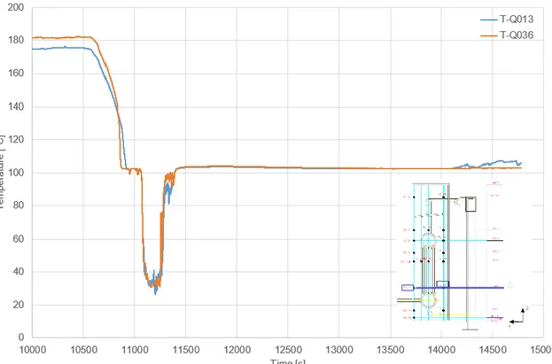
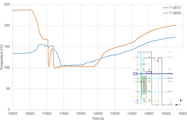
After this first phase of water injection, due to the low level reached in the HXP, the steam production is limited and not sufficient to maintain the HXP pressure high enough to drive the fluid circulation between the pool through the Steam Duct and the Injector. An interface between cold water and steam is present in the Injector, and strong condensation shocks take place. This determines that the HXP pool relative pressure dumps down to negative values till air inlet through the vacuum breaker valve is sufficient to recover the pressure, Figure 4-13. The HXP fluid temperatures are shown in Figure 4-5 to Figure 4-12. Before the water injection, the air contained in the pool is hot, due to the high temperature of the HX, then temperature decreases for the steam production in the HXP after the first phase of water injection.
The second phase of water injection occurs between 11039 and 11260 s when F045 valve is opened at 11039 s and completely closed at 11260 s. At time 11050 s, HXP level reaches the maximum value of 3.4 m, following the second water injection. The OP level is reported in Figure 4-2. Level decreasing is observed during the two phases of water pouring-off towards the HXP. The HXP fluid temperatures decrease rapidly due to the progressive covering of the HXP (some thermocouples are wetted by the fluid).
After the F045 valve is opened for the second injection and power begins to be exchanged heavily from the primary to the pool side, the primary side pressure decreases rapidly, so it is increased, regulating the incoming steam in the pressure vessel, in order to compensate the pressure
Ricerca Sistema Elettrico Sigla di identificazione ADPFISS – LP1 - 126 Rev. 0 Distrib. L Pag. di 17 41
decreasing due to the heat removal. After about 550 s, the pressure average value returns to 7 MPa, Figure 4-1.
While in the first phase of water pouring-off, power exchanged from the primary to the pool side is quite low (around 3.5 MW), because of the low water level in the HXP, it increases by increasing the level, up to reaching the maximum value of about 21 MW (Figure 4-3). The steam flowrate entering the HX and the condensate flowrate exiting the HX increase and are shown in Figure 4-4.
When the maximum level of the HXP is reached (3.4 m) the quasi-steady-operation of the system begins. In this case the triggering valve F-045 is closed during the quasi-steady-operation, thus the window related to the maximum removed power (around 21 MW) is relatively short (around 600 s).
The maximum steam flow rate condensed in the HX is around 13 kg/s (quasi-steady flowrate in PHW 2, relevant thermal hydraulic aspect 2), Figure 4-4. In the HXP saturation is reached early and temperature stabilises around 104°C, corresponding to the saturation at the pressure in the HXP, Figure 4-13. The production of steam in the HXP in this phase is high and the injection of steam in the OP, passing through the Steam Duct and the injector, limits the thermal stratification in the OP at least until about 12500 s. The OP temperatures are shown in Figure 4-14.
After 11845 s, due to the reduction of the HXP level (for the boil-off) and the progressive HX uncovering, the removed power starts to decrease sensibly. Correspondingly, also the steam and condensate flow rate reduces. The boil-off in the HXP brings to a level increase in the OP. In Figure 4-14 it is possible to notice the thermal stratification in the OP starting from 12500 s when the steam flow rate from the injector is no longer sufficient to promote mixing.
The trend of the HX wall temperatures on the headers during the test is reported in Figure 4-15. It is possible to observe the temperature fall consequently to the HXP flooding and later the temperature rising when the HX Pool dries-out.
Table 4-1 summarizes the opening and closure time of the valve that controls the transient. Table 4-2 shows the Main Relevant thermal hydraulic aspect related to the test 7 Part 1.
Ricerca Sistema Elettrico Sigla di identificazione ADPFISS – LP1 - 126 Rev. 0 Distrib. L Pag. di 18 41
Table 4-1: Test 7 Part 1 valve events timing [1]
Event Time [s]
Triggering valve (F-045) first opening 10475 Triggering valve (F-045) first closure 10608 Triggering valve (F-045) second opening 10621 Triggering valve (F-045) second closure 10655 Triggering valve (F-045) final opening 11039 Triggering valve (F-045) final closure 11260
Table 4-2: Main Relevant thermal hydraulic aspect related to the Test 7 Part 1 [1]
Relevant Thermal Hydraulic aspects Time [s] Quantity
Triggering valve (F045) opening and closure 10475 - 10608 Triggering valve (F045) opening and
re-closure 10621 - 10655
Maximum level in the HX Pool for the first
filling step 10683 1.41 m
Small Heat removal from the primary side 10600 – 11000 3.5 MW Slow water consumption in the HX Pool 11049 From 1.41 m to 1.4 m Instabilities for steam condensation in the
Injector 10930 - 11290
Negative HXP relative pressure
Triggering valve (F045) opening and closure 11039 - 11260
Maximum level in the HX Pool 11050 3.4 m
Maximum exchanged power 11260 – 11845 21.5 MW
HX Pool minimum level 14800 1.25 m
Ricerca Sistema Elettrico Sigla di identificazione ADPFISS – LP1 - 126 Rev. 0 Distrib. L Pag. di 19 41
Figure 4-1: TEST 7 PART 1 - Primary side pressure
Ricerca Sistema Elettrico Sigla di identificazione ADPFISS – LP1 - 126 Rev. 0 Distrib. L Pag. di 20 41
Figure 4-3: TEST 7 PART 1 - HX exchanged power
Ricerca Sistema Elettrico Sigla di identificazione ADPFISS – LP1 - 126 Rev. 0 Distrib. L Pag. di 21 41
Figure 4-5: TEST 7 PART 1 - HX pool temperatures (level 1)
Ricerca Sistema Elettrico Sigla di identificazione ADPFISS – LP1 - 126 Rev. 0 Distrib. L Pag. di 22 41
Figure 4-7: TEST 7 PART 1 - HX pool temperatures (level 3)
Ricerca Sistema Elettrico Sigla di identificazione ADPFISS – LP1 - 126 Rev. 0 Distrib. L Pag. di 23 41
Figure 4-9: TEST 7 PART 1 - HX pool temperatures (level 5)
Ricerca Sistema Elettrico Sigla di identificazione ADPFISS – LP1 - 126 Rev. 0 Distrib. L Pag. di 24 41
Figure 4-11: TEST 7 PART 1 - HX pool temperatures (level 7)
Ricerca Sistema Elettrico Sigla di identificazione ADPFISS – LP1 - 126 Rev. 0 Distrib. L Pag. di 25 41
Figure 4-13: TEST 7 PART 1 - HX pool relative pressure
Ricerca Sistema Elettrico Sigla di identificazione ADPFISS – LP1 - 126 Rev. 0 Distrib. L Pag. di 26 41
Ricerca Sistema Elettrico Sigla di identificazione ADPFISS – LP1 - 126 Rev. 0 Distrib. L Pag. di 27 41 4.2 Test 7 Part 2
This test is characterized by three phenomenological windows:
1. 0 s – 531 s (maximum level in the HXP): Increase of level in one step in the HXP with a consequent increase of the exchanged power removed. Relevant thermal hydraulic aspects are:
1. HXP level increase 2. OP level decrease
3. Mass flow increase in-tube side 4. Power removed increase
5. Progressive covering of the HX in the pool side
2. 531 s – 2282 s (HX power around 20 MW, the ending time of the PHW is when the HX power decreases under 20 MW): Quasi-steady-state operation starting from the HXP level of 3.3 m. Relevant thermal hydraulic aspects are:
1. Quasi-steady-state power removed 2. Quasi-steady-state flow rate in-tube side 3. Initial boil off in the HXP
4. Instabilities in the OP water level
3. 2282 s – 5735 s: Boil off in the HXP with a consequent level reduction. Therefore reduction of power removed (accelerated level decrease by opening of the pool discharge valve). Relevant thermal hydraulic aspects are:
1. Boil off in the HXP
2. Reduction of HXP level and OP level due to the accelerated water draining from the drain valve
3. Reduction of removed power 4. Reduction of flow rate in-tube side
5. Progressive uncovering of the HX in the pool side
The second part of the test starts with the HXP containing a water level of 1.12 m in saturation conditions and the remaining part full of superheated steam, the OP full of warm water and the in-tube side pressure of 7 MPa. The PV pressure is shown in Figure 4-16. Valve F045 begins to be opened at time 300 s and it is completely open at 326 s (26 s opening time). The same valve is
Ricerca Sistema Elettrico Sigla di identificazione ADPFISS – LP1 - 126 Rev. 0 Distrib. L Pag. di 28 41
closed at 3338 s in 123 s in order to isolate the two pools and investigate the trend of power as a function of the HXP level.
The HXP level begins to increase at time 310 s. At time 531 s, the HXP reaches the maximum level of 3.25 m, then oscillations follows until about 1500 s, Figure 4-17. The OP level is reported in the same figure. After the early OP level decreasing for the water pouring-off to the HXP, strong and fast oscillations are observed in the OP level, due to the condensation of steam produced in the HXP and flowing through the injector.
The pressure is maintained around the set point value of 7 MPa until the depressurisation of the plant is started at 4685 s, Figure 4-16.
The exchanged power is shown in Figure 4-18. It is possible to observe that the removed power follows the trend of level in the HXP and it is quite stable around 20 MW until the level does not decrease below 2.2 m (about 2400 s), Figure 4-17. The HX steam and condensate flowrate are shown in Figure 4-19. The condensed steam flowrate at the maximum exchanged power is about 13 kg/s.
The HXP fluid temperatures are shown in Figure 4-20 to Figure 4-27. Before the water injection, superheated steam is contained in the upper part and water at saturation condition in the lower one. After the HXP flooding and water boiling, all temperature stabilise around 104°C, corresponding to the saturation at the pressure in the pool, Figure 4-28. Pressure in the HXP is sufficient to drive steam in the OP through the Steam Duct and the Injector.
Steam, accelerated into the OP by the Injector, promotes the water circulation and mixing in the OP. All the OP fluid temperatures are shown in Figure 4-29 and it is possible to notice the mixing promoted by the injector and then the reaching of saturation conditions.
At time 1150 s, when the majority of OP temperatures is between 80°C and 90°C, the level decreasing in the pools is accelerated by opening the discharge valve F031. The valve is left open for the remaining part of the test. At this point, the Injector outlet is uncovered and steam arriving from the Steam Duct is discharged through the boil-off pipe. After the F045 valve between the two pools is closed (from 3338 s to 3461 s), the HXP level decreases more rapidly and consequently the exchanged power the steam and condensate flow rate.
The trend of the HX wall temperatures on the headers is reported in Figure 4-30. It is possible to observe the temperature of the upper header fall consequent to the HXP flooding; the lower header wall temperature stabilizes at about 5°C above the saturation temperature for the entire duration of the transient.
Ricerca Sistema Elettrico Sigla di identificazione ADPFISS – LP1 - 126 Rev. 0 Distrib. L Pag. di 29 41
Table 4-3 summarizes the opening and closure time of the valves that control the transient. Table 4-4 shows the Main Relevant thermal hydraulic aspect related to the Test 7 Part 2.
Table 4-3: Test 7 Part 2 valve events timing [1]
Event Time [s]
Triggering valve (F-045) opening (in 26s) 300 Overall Pool discharge valve (F-031) opening 1150 Triggering valve (F-045) closure (in 123 s) 3338
Table 4-4: Main Relevant thermal hydraulic aspect related to the Test 7 Part 2 [1]
Relevant Thermal Hydraulic aspects Time [s] Quantity
Triggering valve (F045) opening 326 (opened in 26 s)
Maximum level in the HXP 531 3.25 m
Maximum exchanged power 531 – 2282 21 MW
OP discharge valve F031 opening 1150
Triggering valve F045 closure 3338 (closed in 123 s) HX Pool level decreasing and loss of mass from
the boil-off 2282 – 5735
Primary side depressurization beginning for end
Ricerca Sistema Elettrico Sigla di identificazione ADPFISS – LP1 - 126 Rev. 0 Distrib. L Pag. di 30 41
Figure 4-16: TEST 7 PART 2 - Primary side pressure
Ricerca Sistema Elettrico Sigla di identificazione ADPFISS – LP1 - 126 Rev. 0 Distrib. L Pag. di 31 41
Figure 4-18: TEST 7 PART 2 - HX exchanged power
Ricerca Sistema Elettrico Sigla di identificazione ADPFISS – LP1 - 126 Rev. 0 Distrib. L Pag. di 32 41
Figure 4-20: TEST 7 PART 2 - HX pool temperatures (level 1)
Ricerca Sistema Elettrico Sigla di identificazione ADPFISS – LP1 - 126 Rev. 0 Distrib. L Pag. di 33 41
Figure 4-22: TEST 7 PART 2 - HX pool temperatures (level 3)
Ricerca Sistema Elettrico Sigla di identificazione ADPFISS – LP1 - 126 Rev. 0 Distrib. L Pag. di 34 41
Figure 4-24: TEST 7 PART 2 - HX pool temperatures (level 5)
Ricerca Sistema Elettrico Sigla di identificazione ADPFISS – LP1 - 126 Rev. 0 Distrib. L Pag. di 35 41
Figure 4-26: TEST 7 PART 2 - HX pool temperatures (level 7)
Ricerca Sistema Elettrico Sigla di identificazione ADPFISS – LP1 - 126 Rev. 0 Distrib. L Pag. di 36 41
Figure 4-28: TEST 7 PART 2 - HX pool relative pressure
Ricerca Sistema Elettrico Sigla di identificazione ADPFISS – LP1 - 126 Rev. 0 Distrib. L Pag. di 37 41
Figure 4-30: TEST 7 PART 2 - Heat exchanger upper and lower headers wall temperature
Ricerca Sistema Elettrico Sigla di identificazione ADPFISS – LP1 - 126 Rev. 0 Distrib. L Pag. di 38 41
5 Conclusion
This report presents the PERSEO facility and the experimental transient selected for the benchmark activity within the NEA/CSNI/WGAMA “Thermal-hydraulics of passive safety systems in water-cooled reactors”.
Experimental Test 7 has been selected for its completeness since it is a full pressure test that verifies both the stability of the plant and the long term cooling capability of the system. Test 7 Part 1 is a stability test aimed at the observation of the system behaviour with different water levels in the Heat Exchanger Pool. Test 7 Part 2 is related to the verification of the long term cooling capability of the system.
Ricerca Sistema Elettrico Sigla di identificazione ADPFISS – LP1 - 126 Rev. 0 Distrib. L Pag. di 39 41
Abbreviations
DHR Decay Heat Removal
HX Heat Exchanger
HXP Heat Exchanger Pool
IC Isolation Condenser
OP Overall Pool
PERSEO in-Pool Energy Removal System for Emergency Operation
PHW Phenomenological Window
PRHR Passive Residual Heat Removal system
Ricerca Sistema Elettrico Sigla di identificazione ADPFISS – LP1 - 126 Rev. 0 Distrib. L Pag. di 40 41
References
[1] R. Ferri, A. Achilli, S. Gandolfi, PERSEO PROJECT Experimental Data Report, SIET 01 014 RP 02, 2002
[2] G. Bandini, P. Meloni, M. Polidori, C. Lombardo, Validation of CATHARE V2.5 thermal-hydraulic code against full-scale PERSEO tests for decay heat removal in LWRs, Nuclear Engineering and Design, 241, pp. 4662-4671, 2011
[3] R. Ferri, A. Achilli, G. Cattadori, F. Bianchi, P. Meloni, Design, experiments and Relap5 code calculations for the PERSEO facility, Nuclear Engineering and Design, 235, n. 10-12, pp. 1201-1214, 2005
[4] NEA/CSNI/R(2016)14, A state-of-the-art report on scaling in system thermal hydraulics applications to nuclear reactor safety and design, 2017
Ricerca Sistema Elettrico Sigla di identificazione ADPFISS – LP1 - 126 Rev. 0 Distrib. L Pag. di 41 41
Short description of the research group
The research group involved in the activity is composed by a full professor (Mario De Salve), a researcher (Cristina Bertani), two PhD students (Andrea Bersano and Nicolò Falcone) and an emeritus professor (Bruno Panella).
De Salve, Bertani and Panella have a long experience at di Torino in the field of nuclear engineering, in particular in the thermal-hydraulic and safety sector. They have conducted several researches at the Energy Department laboratory and they are authors of several papers published in national and international journals and in conference proceedings. They are authors of many previous PAR reports.
Falcone is an Energy and Nuclear Engineer currently at the first year of his PhD in Energetics at Politecnico di Torino.
Bersano is an Energy and Nuclear Engineer currently at the second year of his PhD in Energetics at Politecnico di Torino.
More details and the list of publications can be found on the website of Politecnico di Torino (http://www.polito.it).
![Figure 2-3 Location of the temperature measurements in the Heat Exchanger Pool (HXP) [1]](https://thumb-eu.123doks.com/thumbv2/123dokorg/5605869.67940/9.892.163.767.100.1069/figure-location-temperature-measurements-heat-exchanger-pool-hxp.webp)
![Figure 2-4 Location of the temperature measurements in the Overall Pool (OP) [1]](https://thumb-eu.123doks.com/thumbv2/123dokorg/5605869.67940/10.892.180.731.97.1115/figure-location-temperature-measurements-overall-pool-op.webp)


![Table 4-2: Main Relevant thermal hydraulic aspect related to the Test 7 Part 1 [1]](https://thumb-eu.123doks.com/thumbv2/123dokorg/5605869.67940/18.892.84.770.415.787/table-main-relevant-thermal-hydraulic-aspect-related-test.webp)