UNIVERSITÀ DEGLI STUDI DI MESSINA
DIPARTIMENTO DI SCIENZE CHIMICHE, BIOLOGICHE,
FARMACEUTICHE ED AMBIENTALI
C
ORSO DID
OTTORATO INS
CIENZEC
HIMICHE - XXXI CICLOPROGETTAZIONE, SINTESI, ANALISI E PROPRIETÀ DI SISTEMI MOLECOLARI FUNZIONALI
Playing with light on molecular and
hybrid nanomaterials
Emanuele La Mazza
Supervisor
Coordinator
Prof. Fausto Puntoriero
Prof. Sebastiano Campagna
2015-2018
TABLE OF CONTENTS
Introduction
1 Outlines of the thesis 3 References 5Chapter 1
Photoinduced Energy Transfer: a Brief Description 7 1.1 Coulombic mechanism 11 1.2 Exchange mechanism 13 References 17Chapter 2
Artificial Light Harvesting and Dendrimer as Antenna Systems 19 Introduction 19 2.1 Dendrimers 21 2.2 Ru(II) and Os(II) polypyridine complexes 26 2.3 Bridging ligand 31 2.4 Synthetic strategy 32 2.5 Complexes previously studied as antenna systems 35 References 40Chapter 3
Mesoporous silica nanoparticles as host-guest systems 44 3.1 Mesoporous structures 44 3.2 Functionalisation 47 3.3 Host-guest systems 53 3.3.1 Approach 1 54 3.3.2 Approach 2 57 3.4 Energy Transfer processes 59 3.4.1 Homo-Energy transfer and Aggregates formations 63 References 66Chapter 4
A New Heptanuclear Complex as Light-Harvesting Antenna 71 4.1 Synthesis and properties of ligand L 71 4.2 Synthesis of Ru(II) and Os(II) complexes 72 4.3 Redox behaviour 77 4.4 UV/Vis characterisation 82 4.5 Luminescence 84 4.6 Pump-probe Transient Absorption Spectroscopy 88 4.7 Conclusions 91 References 92Chapter 5
Light-Harvesting with Organic Molecules inside Mesoporous Organosilica 93 Introduction 93 5.1 Hybrid BODIPY-silica nanomaterials 94 5.1.1 Synthesis 94 5.1.2 Structure and Morphology 95 5.1.3 Photophysical properties and TAS 97 5.2 Hybrid piridinium-silica nanoparticles 103 5.2.1 Piridinium properties 104 5.2.2 Hybrid nanoparticles synthesis and morphology 106 5.2.3 Photophysics 106 5.3 Hybrid systems for energy/electron transfer 109 5.3.1 Synthesis 109 5.3.2 Photophysics 110 5.4 Conclusions 116 References 118Chapter 6
Ru(II) Complexes Appended with Additional Organic Chromophores in Hybrid Silica Nanostructures 121 6.1 Hybrid MCM-41 nanoparticles 123 6.2 Hybrid mesoporous silica spheres 125 6.3 Adding new functionalities 129 6.4 Conclusions 130 References 132iii
Chapter 7
Interaction with Bio-Materials 135 Introduction 135 7.1 DNA structure 135 7.2 Interaction of small molecules with DNA 138 7.3 Intercalation model 140 7.3.1 Ru(II) complexes as intercalators 142 7.4 Interaction of Ru2L with DNA 146 7.5 Cellular internalisation studies and cytotoxicity 149 7.6 Conclusions 152 References 154CONCLUSIONS
157Experimental Chapter
159 EC.1 Materials and methods 159 EC.1.1 Erythrocytes isolation 162 EC.1.1.1 Cellular internalisation and cytotoxic effects 162 EC.1.1.2 Statistical analysis 163 EC.2 Syntheses 163 EC.3 Supplemental Ru6Os characterisations 173 References 175Introduction
“I remember in college, another guy and I had an idea. We wanted to find out what made the grass grow green. That sounds silly, but that’s the biggest research problem in the world today and I’ll tell you why. Because there’s a tiny little engine in the green of this grass and in the green of the trees that has the mysterious gift of being able to take energy from the rays of the Sun and store it up. You see that's how the heat, and power, and coal, and oil, and wood is stored up. We thought that if we could find the secret of all those millions of little engines in this green stuff we can make big ones and then we can take power we can ever need right from the sunrays.” (J. Stewart in "You Can't Take It With You" by Frank Capra - 1938)
Watching this movie one can realise how huge is the importance of this particular problem. That someone 80 years ago in a movie explained the difficulty of using solar light for large-scale energy applications is amazing, as it is hard to believe how long we took (in a famous address presented before the VIII International Congress of Applied Chemistry, held in New York in 1912, G. Ciamician strongly suggested to replace “fossil solar energy” with the energy that the Earth receives from the Sun every day) to understand how photosynthesis works.
Combustion of fossil fuels is today the main source of energy useful for several
sectors, such as industry, transportation, communication, welfare and so on.1
However, despite the relatively abundance and ease of extraction, supplies of fossil
fuels are not limitless.1 They are not a long-term solution for a durable Earth energy
supply; the average worldwide energy consumption in a year is 16.2 TW2,3 and this
value is doomed to rise. Moreover, another problem that is getting worse year by year is related to the pollution due to the combustion of such fuels: from combustion processes there derive an huge amount of CO2 (causing the greenhouse effect) and
the age in which seeking alternative energy sources will not be just an alternative, but a dreadful reality to face.
One of the most promising alternative energy sources may derive by the photochemical conversion of solar energy. Sunlight is, in fact, a source of energy that is renewable, environmentally clean, inexpensive, available everywhere and abundant.4,5 Earth receives an inconceivable power flow from the Sun: 120,000 TW
per year of electromagnetic radiation of various wavelengths. So, the quantity of energy that continuously arrives from the Sun largely exceeds human needs.5,6,7
Unluckily, light energy is intermittent and too diffuse to be optimally used as such, so it is necessary converting it in other types of energy: heat and electric energy might be valid choices, but the most convenient way is storing solar energy as chemical one; after all, this is what Nature does everyday, as well as the reason why all of us exist on this planet. Natural photosynthesis is, indeed, an efficacious example of such photochemical conversion process and mimicking it could grant us high-energy content chemicals (fuels) from low-energy content materials. A possible example is
the photoinduced water splitting process.8 This process leads to obtaining molecular
oxygen and, above all, molecular hydrogen, which is considered the fuel of the future, thanks its several advantages: it has a high specific enthalpy value9,10,11 and the
combustion of its regenerates water, releasing energy, which leads to a sustainable cycle that is environmentally safe and generates no polluting subproducts.8,11
By learning the lesson from Nature, an artificial photosynthetic system should include: i) an antenna system, ii) a reaction centre, and iii) multielectron transfer catalysts.
The first step in this direction lies on catching solar light. A mechanism by which natural systems accomplish this task relies on the use of spatial constraints to assemble multiple pigments into highly organised light-harvesting antennae. Although, in these systems, the various pigment subunits are basically identical one another, the driving force for energy migration is generated by slightly differences on their excited-state energy, as a consequence of their position within the supramolecular structure and therefore of their environment. This is realised by using protein membranes as scaffolds that allow chlorophyll chromophores to convey excitation energy to suitable reaction centres, in an overall system able to damp
3
thermal losses and provide long-term stability.12, 13, 14 In doing so, nature has evolved
to combine the versatility of molecular systems with the organisation of nanomaterials.
The present thesis collects the principal results I obtained during the three-year Ph.D. course in Chemical Sciences, on systems able to collect light and elaborate the information transmitted by photons. The research work has been performed in the Laboratory of Photochemistry of the Department of Chemical, Biological, Pharmaceutical and Environmental Sciences at the University of Messina under the supervision of Prof. Fausto Puntoriero and partially in the Laboratory of Photochemistry of the School of Natural and Environmental Sciences at Newcastle University of Newcastle upon Tyne, UK, under the supervision of Prof. Fabio Cucinotta. The entire work of this thesis arises from the desire to develop light-harvesting antennas by using coordination compounds, organic dyes and host-guest hybrid system assembled on mesoporous silica nanomaterials. All the results are resumed as follow.
Outlines of the thesis
Chapter 1 contains basic information about energy transfer process, which is fundamental in photosynthetic systems.
Chapter 2 focuses on dendrimers, which, in virtue of their properties, are particularly suitable to be used as photoactive well-organised multicomponent molecular nanomaterial. It deals also with the photophysical properties of dendrimeric antenna systems based on Ru(II) and Os(II) polypyridine subunits, previously studied by photochemistry research group in Messina.
Chapter 3 describes mesoporous silica nanoparticles as host systems for molecules, in particular species that undergoes energy transfer processes.
Chapter 4 focuses on the synthesis and on the discussion of the photo- and electrochemical properties of a series of metal containing complexes and in particular of a heptanuclear dendrimer based on Ru(II) and Os(II) subunits on a new tris-chelating bridging ligand.
Chapter 5 and Chapter 6 deal with hybrid mesoporous silica nanomaterials as host-guest systems. The species used as guests are organic dyes (Chapter 5) and Ru(II) metal complex (Chapter 6). In Chapter 5 there are discussed the photophysical properties of two organic dyes once trapped, both separately and mixed, in silica nanoparticles (MCM-41 type). In Chapter 6 there are reported the preparation and the study of a hybrid antenna system trapped in two types of silica nanoparticles (MCM-41 and mesoporous silica spheres). The possibility of integrating other active species (iridium oxide nanoparticles in this case) to introduce new functionalities has been explored too.
It is evident that light has become one of the most powerful and extensively used tool not only in chemistry and material sciences but also in cell biology and related areas of the biomedical sciences, this because light allows for performing non-invasive measurements, extremely good precision, accuracy and modularity. So, in Chapter 7 I report on preliminary study of the efficiency of a dinuclear complex discussed in Chapter 4 to act as light switch for DNA. The ability of this compound to permeate the cellular membrane of erythrocytes, as well as the cellular internalisation behaviour of the hybrid materials discussed Chapter 7, have been preliminary discussed.
5
References
1) M. Hambourger, G. F. Moore, D.M. Kramer, D. Gust, A. L. Moore, T. A. Moore, Chem. Soc. Rev., 2009, 38, 25.
2 ) (a) Energy Information Association; U.S. Department of Energy; Washington DC; www.eia.doe.gov (accessed January 2010); (b) J. R. McKone, N. S. Lewis, H. G. Gray, Chem. Mater., 2014, 26, 407.
3) T. R. Cook, D. K. Dogutan, S. Y. Reece, Y. Surendranath, T. S. Teets, D. G. Nocera, Chem. Rev., 2010, 110, 6474.
4) (a) N. Armaroli, V. Balzani, Angew. Chem., Int. Ed., 2007, 46, 52; (b) M. H. V. Huynh, T. J. Meyer, Chem. Rev., 2007, 107, 5004; (c) J. P. McEvoy, G. W. Brudvig, Chem. Rev., 2006, 106, 4455; (d) M. Wasielewski, Acc. Chem. Res., 2009, 42, 1910; (e) D. Gust, T. A. Moore, A. L. Moore, Acc. Chem. Res., 2009, 42, 1890; (f) C. Herrero, A. Quaranta, W. Leibl, A. W. Rutherford, A. Aukauloo, Energy Environ. Sci., 2001, 4, 2353.
5) (a) N. Armaroli, V. Balzani, Energy for a Sustainable World: From the Oil Age to a Sun-Powered Future, Wiley-VCH, Weinheim, 2011; (b) N. Armaroli, V. Balzani, N. Serpone, Powering Planet Earth, Wiley-VCH, Weinheim, 2013. 6) (a) A. J. Bard, M. A. Fox, Acc. Chem. Res., 1995, 28, 141; (b) N. S. Lewis, D. G. Nocera, Proc. Natl. Acad. Sci. USA, 2006, 103, 15729; (c) H. B. Gray, Nature Chem., 2009, 1, 7. 7) B. D. Sherman, M.D. Vaughn, J. J. Bergkamp, D. Gust, A. L. Moore, T. A. Moore, Photosynth. Res., 2014, 120, 59. 8) (a) T. J. Meyer, Nature, 2008, 451, 778; (b) F. Liu, J. J. Conception, J. W. Jurss, T. Cardolaccia, J. L. Templeton, T. J. Meyer, Inorg. Chem., 2008, 47, 1727; (c) J. W. Jurss, J. C. Concepcion, M. R. Norris, J. L. Templeton, T. J. Meyer, Inorg. Chem., 2010, 49, 3980; (d) S. Y. Reece, J. A. Hamel, K. Sung, T. D. Jarvi, A. J. Esswein, J. J. H. Pijpers, D. G. Nocera, Science, 2011, 334, 645; (e) L. Kohler, N. Kaveevivitchai, R. Zong, R. P. Thummel, Inorg. Chem., 2014, 53, 912. 9) (a) S. M. Arachchige, K. J. Brewer, R. Crabtree (Ed.), Energy Production and Storage;
Inorganic Chemical Strategies for a Warming World, John Wiley & Sons, Chichester, West Sussex, UK, 2010, 143-171; (b) T. S. Teets, D. G. Nocera, Chem. Commun., 2011, 47, 9268. 10) (a) F. Wang, W. G. Wang, H. Y. Wang, G. Si, C. H. Tung, L. Z. Wu, ACS Catal., 2012, 2, 407; (b)
The Hydrogen Economy: Opportunities, Costs, Barriers, and R&D Needs, U.S. National Research Council and U.S. National Academy of Engineering, 2004.
11) D. Gust, T. A. Moore, A. L. Moore, Faraday Discuss., 2012, 155, 9.
12) J. Deisenhofer, O. Epp, K. Miki, R. Huber, H. Michel, Nature 1985, 318, 618-624. 13) W. Kuhlbrandt, N. W. Da, F. Yoshinori, Nature 1994, 367, 614-621
Chapter 1
Photoinduced Energy Transfer: a Brief Description
Photoinduced energy transfer plays a key role in both natural and artificial systems. Examples are natural photosynthesis as well as synthetic assemblies for solar energy conversion and information technologies.
Generally speaking, when electronic excitation energy absorbed by a chromophore D (donor) is transferred to a chemically different chromophore A (acceptor) a photoinduced energy transfer process takes place, according to:
D* + A
→
D + A*
In this case the process is called heterotransfer. This process is possible provided that the donor emission spectrum partially overlaps the acceptor absorption spectrum.
If donor and acceptor are identical, it is called homotransfer:
D* + D
→
D + D*When the process can repeat itself so that the energy migrates over several molecules, it is called energy migration.
It is important to distinguish between radiative and non-radiative transfer, in fact they have different effects on the characteristics of fluorescence emission from the donor, which allows us to make a distinction between these two types of transfer. Moreover, the factors governing the efficiency of radiative and non-radiative transfers are not the same (apart from the spectral overlap, which is required for both processes).
Radiative transfer is a two-step process by which D* emits a photon that is
resorbed by A and is observed when the average distance between D and A (or D) is larger than the excitation wavelength:
1) D*
→
D + hν2) hν + A
→
A* or hν + D→
D*interaction between the partners and is not dependent on the distance between them, while depends on the concentration of A, the optical path length of emitted photons across the sample and the spectral overlap. This process does not affect the lifetime of the D* excited state, but can lead to distortions of the emission spectrum from D*.
This process is often called trivial transfer because of the simplicity of the phenomenon, but in reality the quantitative description is quite complicated because it depends on the size of the sample and its configuration with respect to excitation and observation. Radiative transfer results in a decrease of the donor fluorescence intensity in the region of spectral overlap. Such a distortion of the fluorescence spectrum is called the inner filter effect.
Non-radiative transfer of excitation energy occurs without any emission of
photons at distances less than the wavelength and result from shot- or long-range interactions between molecules. Consequently, such a transfer provides a tool for determining distances of a few tens of ångströms between chromophores. The transfer of excitation energy plays a major role in photosynthetic systems. Figure 1.2 (Left): illustration of the integral overlap between the emission spectrum (blue) of the donor and the absorption spectrum (red) of the acceptor. (Right): energy level scheme of donor and acceptor molecules showing the coupled transitions.
Non-radiative transfer process requires some interaction between a donor molecule and an acceptor molecule, and it can occur if the emission spectrum of the donor overlaps the absorption spectrum of the acceptor, so that several vibronic transitions in the donor have practically the same energy as the corresponding
9 transitions in the acceptor. Such transitions are coupled (see Figure 1.2), i.e. are in resonance. From the spectroscopic viewpoint both for molecular and supramolecular systems the transfer can be dealt with as an isoenergetic non-radiative deactivation between two ‘‘localised’’ electronically excited states: D*–L–A
→
D–L–A* The rate constant can be obtained by an appropriate Fermi golden rule expression (Equation 1.1): ken=2π
h ΨD*·A| ˆH en| Ψ D·A* 2 FCen (eq. 1.1)where
H
ˆ
en is the electronic coupling operator between the two excited statesinterconverted by the energy-transfer process and FCen is an appropriate Franck–
Condon factor. The Franck–Condon factor can be cast either in classical1 or quantum mechanical2 terms. Classically, it accounts for the combined effects of energy gradient and nuclear reorganisation on the rate constant. In quantum mechanical terms, the FC factor is a thermally averaged sum of vibrational overlap integrals (Equation 1.2):
FC
en=
θ
D*0θ
A0|θ
Dmθ
A*n 2=
m,n∑
θ
D*0θ
Dm|θ
A0θ
A*n 2 m,n∑
(eq. 1.2) Experimental information on this term can be obtained from the overlap integral between the emission spectrum of the donor and the absorption spectrum of the acceptor: FCen is negligible if D* lies at lower energy than A* (Figure 1.3a), quitesmall if the two excited states are isoenergetic (Figure 1.3b) and large if D* is higher than A* in energy (Figure 1.3c).
As shown in Figure 1.3, energy transfer is an isoenergetic process that takes place after vibrational relaxation. This is usually the case for radiationless transitions. As a consequence, it is a unidirectional process, unless the two excited states are practically isoenergetic.
Figure 1.3 Schematic energy levels (top) and spectral overlap (bottom) between emission of the donor D (blue line) and absorption of the acceptor A (red line) for three different cases: (a) E(D*)>E(A*); (b) E(D*)=E(A*); (c) E(D*)>E(A*). Figure 1.4 Pictorial representations of the coulombic (a) and exchange (b) energy transfer mechanism.
11
The electronic operator involves the HOMO (highest occupied molecular
orbital) and LUMO (lowest unoccupied molecular orbital) of the energy-donor and energy-acceptor components. Non-radiative energy transfer can result from different mechanisms: the interactions may be coulombic and/or due to intermolecular orbital
overlap. Hence, can be split in two additive terms, a coulombic term (
H
ˆ
C) andan exchange term ( ˆHE) (Figure 1.4). The two terms depend differently on the parameters of the system (spin of ground and excited states, door-acceptor distance, etc.). Each can become predominant depending on the specific system and experimental conditions.
1.1 Coulombic mechanism
The coulombic mechanism (also called resonance, Förster resonance energy
transfer (FRET))3,4, is a long-range mechanism that does not require physical contact between donor and acceptor. It can be shown that the most important term, within the coulombic interaction, is the dipole–dipole term, which obeys the same selection rules as the corresponding electric dipole transitions of the two partners (D*
→
D and A→
A*, Figure 1.4a). Coulombic energy transfer is therefore expected to be efficient in systems in which the radiative transitions connecting the ground and the excited state of each partner have high oscillator strength and in which each partner does not change its spin multiplicity. The rate constant for the dipole–dipole coulombic energy transfer is proportional toΨ
D*·A| ˆ
H
en| Ψ
D·A* 2; as the interaction between two point dipoles falls off with the third power of the distance, the rate constant falls off with the sixth power of the distance rAB between the two partners. The rate constant can be expressed as a function of the spectroscopic and photophysical properties of the two molecular components (Equation 1.3): kenF = 8.8·10−25 K 2 Φ n4r AB 6τ
JF (eq. 1.3) where K is an orientation factor which accounts for the directional nature of the dipole-dipole interaction (from statistics considerations, assumed as 0.66), Φ and τˆ
H
enˆ
are the luminescence quantum yield and lifetime of the donor, respectively, n is the solvent refractive index, rAB is the distance between donor and acceptor. The spectral overlap JF is given by Equation 1.4:
J
F=
F(ν )ε(ν ) / ν
4dν
∫
F(ν )dν
∫
(eq. 1.4) where F(!) is the luminescence spectrum of the donor and ε(!) is the absorption spectrum of the acceptor on an energy scale (cm-1). Note that the rate constant (in s-1) is a first-order rate constant, representing the energy transfer between D* and A held at a fixed distance and relative orientation.The overlap integral can be expressed in terms of wavelength, in which case appropriate proportionally constant should be considered that match those of
Equation 1.4:
J
F=
F(λ)ε(λ) / λ
4d λ
∫
F(λ)dλ
∫
(eq. 1.5)The rate constant kFen can also be expressed in terms of Equation 1.6:
kenF = R0 6 rAB6
τ
(eq. 1.6) where τ is the lifetime of the donor in the absence of the acceptor and R0, named critical transfer distance, is the distance in which energy transfer has 50% efficiency(half of D* decays by intrinsic paths and half energy transfer to A). Förster energy transfer is thus widely applied in determining the distance between D and A markers attached to biopolymers.5
With good spectral overlap integral and appropriate photophysical properties, the
1/r6AB distance dependence enables energy transfer to occur efficiently over
distances substantially exceeding the molecular diameters. The typical example of an efficient coulombic mechanism is that of singlet–singlet energy transfer between large aromatic molecules, a process used by nature in the antenna systems of the
13
photosynthetic apparatus.6 On the basis of spin considerations, the process here
illustrated is doubly forbidden by the coulombic mechanism:
D*(T1) + A(S0)
→
D(S0) + A*(T1)
However, if D exhibits a high phosphorescence quantum yield and good overlap with the singlet absorption of A, coulombic energy transfer can occur, thanks to the long lifetime of the donor species.
As this energy transfer mechanism does not require close contact between D* and A, the rate constant can exceed the rate constant of diffusion and Stern-Volmer plots deviate from linearity.
In the case of an energy migration process (A=D), it does not bring about any change in lifetime of D* or in its emission intensity, but does yield depolarisation of fluorescence.
1.2 Exchange mechanism
The rate constant for the exchange (also called Dexter-type)7 mechanism can be
expressed by Equation 1.7: kenD =2
π
h ΨD*·A| ˆH en| Ψ D·A* 2 JD (eq. 1.7) where the electronic termH
ˆ
en is obtained from the electronic coupling between donor and acceptor, and is exponentially dependent on distance. ΨD*·A| ˆH en| Ψ D·A* 2 = Hen= Hen(0)exp − β en 2 (rAB− r0) ⎡ ⎣ ⎢ ⎤ ⎦ ⎥ (eq. 1.8) the nuclear factor JD is the Dexter overlap integral between the emission spectrum of the donor and the absorption spectrum of the acceptor (Equation 1.9):J
D=
∫
F(ν )ε(ν )dν
F(ν )dν ε(ν )dν
∫
∫
(eq. 1.9)It is worth noting that JD is different from JF (Equation 1.5) because the
normalisation is done not only on the emission spectrum of the donor but also on the absorption spectrum of the acceptor, so that JD is independent of the oscillator
strengths of both partners.
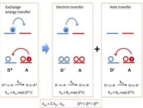
Figure 1.5 Exchange energy transfer can be represented as an electron and a hole transfer. The relationship between the rate constants and the attenuation factors of the three processes are also shown.
The exchange interaction (Figure 1.4b) can best regarded as a double electron transfer process, one electron is moving from the LUMO of the excited donor to the LUMO of the acceptor, and the other from the acceptor HOMO to the donor HOMO. This important insight is illustrated in Figure 1.5, from which it is clear that the attenuation factor
β
en for the exchange energy transfer should be approximately equal to the sum of the attenuation factors for two separated electron transfer processes, that isβ
el for electron transfer between the LUMO of the donor andacceptor, and
β
ht for the electron transfer between the HOMOs (superscript htdenotes hole transfer from the donor to the acceptor).8
The spin selection rules for this type of mechanism arise from the need to obey spin conservation in the reacting pair as a whole, Wigner’s rule.9 This enables the
15
exchange mechanism to be operative in many instances in which the excited states involved are spin-forbidden in the usual spectroscopic sense. Thus, the typical example of an efficient exchange mechanism is that of triplet-triplet energy transfer:
D*(T1) + A(S0)
→
D(S0) + A*(T1)
This sensitisation process is often used to selectively populate triplet states of molecules that do not undergo efficient intersystem crossing following direct excitation: it can be useful for a variety of purposes, including energy upconversion, preparative photochemistry and elucidation of photoreaction mechanisms.
Although the exchange mechanism was originally formulated in terms of direct overlap between donor and acceptor orbitals, it can be extended to coupling
mediated by the intervening medium (i.e., a connecting bridge).10
To summarise, the most important differences between the two non-radiative mechanisms are:
1. Range: coulombic mechanism is a dipole-dipole long-range mechanism (in favourable conditions, efficient over 5 nm); exchange mechanism is a short-range (collisional) mechanism (less than 1 nm) and has an exponential dependence on distance as orbital overlap is required.
2. Media: coulombic mechanism is efficient in rigid media (sphere-of-action kinetics); exchange mechanism is blocked in rigid media when D and A are two species dissolved in diluted solutions.
3. Oscillator strength: coulombic mechanism is fast when both donor and acceptor have large oscillator strength; exchange-mechanism rate is independent from oscillator strength.
4. Stern–Volmer behaviour: coulombic mechanism in fluid solutions shows non-Stern–Volmer kinetics; exchange mechanism in fluid solutions shows Stern–Volmer behaviour: coulombic mechanism in fluid solutions shows non-Stern–Volmer behaviour.
5. Treatment: for coulombic mechanism it is applied the Förster equation for calculating energy transfer rate constants from experimental data on D and A molecules; for exchange mechanism the Marcus-type treatment is applied.
based on energetic considerations:
1. Very endothermic energy transfer processes are in general inefficient (even if spin-allowed) because there is no overlap between donor emission spectrum and acceptor absorption one.
2. Exothermic spin-allowed energy transfer processes are generally efficient. 3. There is no general rule for exothermic spin-forbidden energy transfer processes.
17
References
1) V. Balzani, F. Bolletta, F. Scandola, J. Am. Chem. Soc., 1980, 102, 2152–2163. 2) G. Orlandi, S. Monti, F. Barigelletti, V. Balzani, Chem. Phys., 1980, 52, 313–319.
3) T. Förster, 10th spiers memorial lecture. Transfer mechanisms of electronic excitation, Discuss. Faraday Soc., 1959, 27, 7–17. 4) F. Barigelletti, L. Flamigni,, Chem. Soc. Rev., 2000, 29, 1–12. 5) J. R. Lakowicz, Principle of Fluorescence Spectroscopy, 3rd edn, Springer, New York, 2006. 6) T Pullerits, V. Sundström, Acc. Chem. Res 29, 1996, 381 and references therein., 7) D. L. Dexter, J. Chem. Phys., 1953, 21, 836–850. 8) G. L. Closs, M. D. Johnson, J. R. Miller, P. Piotrowiak, J. Am. Chem. Soc., 1989, 111, 3751–3753. 9) P. Klán, J. Wirz, Photochemistry of Organic Compounds: From Concepts to Practice, John Wiley & Sons, Ltd, Chichester, 2009 10) P. Piotrowiak, Relationship between electron and electronic excitation transfer, in Electron Transfer in Chemistry (ed. V. Balzani), Wiley-VCH Verlag GmbH, Weinheim, 2001, 215–237.
Chapter 2
Artificial Light Harvesting and Dendrimer as Antenna Systems
Introduction
Several photosynthetic organisms exist that perform the photosynthetic process and all of them use the same strategy. The photosynthetic machinery uses three components to drive solar fuel production: (i) the antenna system, (ii) the reaction centre, and (iii) systems for the multielectronic catalysis. They work is sequence, as following: firstly sunlight is absorbed by the antenna systems, which are collections of chromophores that absorb a large range of solar light spectrum. Then, they transfer excitation energy among one another via Föster singlet-singlet energy transfer, and
finally to the next component:1 the reaction centre protein. Here, the energy received
is used for a charge separation process. The so-formed charges are used to obtain the products of the photosynthesis (organic compounds, biomass, fossil fuels, and so on) by multielectronic catalysis. The burning of such products with oxygen by combustion forms the original compounds (water and carbon dioxide) and releases the energy originated from sunlight.2
As explicative example to understand the mechanisms behind the photosynthetic components, deep investigations have been carried out on the Rhodopseudomonas acidophila. Herein, the antenna apparatus is composed by two systems: LH2 and LH1. The first one consists of two organised sets of bacteriochlorophylls, absorbing each at
800 nm and at 850 nm.3 Sunlight absorbed by the higher-energy absorbing set (800
nm) is transferred to the lower-energy absorbing set of chlorophylls (850 nm). The energy is then transferred to LH1, which is larger than LH2 and it is composed by 32 bacteriochlorophylls, even if the structure of the system is not well known. LH1 absorbs at 880 nm and the short distance (30 Å) between the two systems allows a fast energy transfer (3 ps) from LH2 to LH1. In the antenna systems (in particular in LH2), auxiliary chromophores (like carotenoids, phycoerythrins, and phycocyanins) are employed to absorb light in regions where chlorophyll does not absorb, and then they transfer the energy to chlorophylls. Antenna systems are also involved in
photoregulation and photoprotection of the photosynthetic apparatus.1
inside the LH1 system. Then, a photoinduced electron transfer process yields to the formation of a charge separated species, whose charges are captured by the multielectronic catalysts.
Among the others, the photosynthetic mechanisms occurring in the plants appear the most attractive to study and to mimic. In the plants, absorption of light by photosynthetic pigments is followed by a series of energy transfers and charge separation processes which lead to the oxidation of water to molecular oxygen, while the reducing equivalents are used for the reduction of CO2 into carbohydrates. Figure 2.1 Schematic representation of an artificial photosynthetic device.
To perform an artificial photosynthesis many structurally-organised and functionally-integrated components, inspired by natural photosynthetic systems, are needed (schematised in Figure 2.1): (i) the antenna system, an assembly of chromophores which has the function of collecting light energy and conveying it by a series of elementary energy transfer steps to a specific subunit;4,5,6 (ii) the
charge-separation component, which essentially should transform electronic energy into chemical (redox) energy; (iii) multi-electron storage systems, which have to collect more than one electron (or hole) in reversible ways, also in successive steps, and deliver all the collected electrons (or holes) to suitable substrates in a single shot (most of the species which are potentially used to store chemical energy in usable forms need multi-electron processes – this is the case for water splitting or carbon dioxide reduction, for example). It could be noted that each component of this
21
artificial photosynthetic device is itself a multicomponent system, so a hierarchical
supramolecular organisation is required.7
Despite the complexity of this kind of system, the outstanding developments in
supramolecular chemistry8,9 and ultrafast spectroscopy10 in the last decades granted
us a better knowledge to design multicomponent systems. A rational way to design efficient artificial photosynthetic systems is studying the various components separately. Since an optimal antenna system needs a lot of chromophores, a good way to achieve this is using dendrimers;11,12 in fact, because their structure, they can
concentrate a lot of chromophores in a limited space by few synthetic steps. Moreover, choosing between divergent and convergent synthetic strategy allows tuning the system energy gradient. In the research group where I have worked it has been studied dendritic antenna systems based on Ru(II) and Os(II) polypyridine subunits, also in collaboration with research groups in Bologna and Pisa13,14,15.
2.1 Dendrimers
Dendrimers16,17 are well-defined macromolecules exhibiting a tree-like structure
which can be built via an iterative sequence of reaction steps. In a dendrimer it is possible recognise a core and one or more layers of concentric shells containing several repetitive subunits and the number of layers defines the generation of the dendrimer (Figure 2.2). Figure 2.2 Schematic representation of a generic dendrimer.
The interest on dendrimer chemistry has evolved from the simple construction of these intriguing molecules to their characterisation, and finally toward their functionalisation, in view of potential applications in many different fields, such as chemistry, physics, engineering, biology and medicine. Both organic and inorganic units have been introduced in each of the topologically different positions available within the dendrimer structure, i.e. in the core, in the branches, and on the surface. Multiple functionalisations have also been achieved by placing two or more different active units in distinct regions of the same dendrimer. Furthermore, host–guest chemistry can be used to incorporate functional species in the cavities present in the dendrimer’s interior. The interaction of different components, modulated by the dendritic structure, may give rise to a molecular-level device,18,19 that is an assembly
of a discrete number of molecular components designed to achieve a complex function, resulting from the cooperation of the various units.
Molecular level devices, like macroscopic devices, need energy to operate and signals to communicate with the operator. Photons and electrons constitute the most viable answer to this dual requirement. Light is indeed used by Nature, where photons are used as energy in the devices involved in the photosynthetic processes and as signals by the devices involved in vision-related processes. Electrical energy is another simple way to induce molecular-level functions, and electrochemistry is a very useful means to monitor the occurrence of such functions. For all these reasons, it is appealing to design and construct dendrimers containing photo- and redox-active units, which could thus play the role of molecular-level photonic and electronic devices.
It is worth emphasising that the photochemical and photophysical properties of dendrimers are particularly interesting since (i) cooperation among the photoactive components can allow the dendrimer to perform useful functions such as light harvesting and frequency converting, (ii) changes in the photophysical properties can be exploited for sensing purposes with signal amplification, and (iii) the presence of luminescence signals can offer a valuable handle to better understand the dendritic structure and superstructure. On the other hand, the electrochemical properties of dendrimers are interesting since (iv) redox active units present at the core of a dendrimer can be “encapsulated” by the surrounding branches, thus modulating the
23
electron transfer rate, (v) the presence of multiple equivalent, non-interacting units gives rise to the simultaneous exchange of a large and predetermined number of electrons, and (vi) electroactive units of the same or different types can be placed in topologically equivalent or non-equivalent sites of a dendrimer to obtain specific redox patterns. Many new valuable functions can be obtained by introducing photo- and redox-active units in appropriate sites of the dendritic structure. As a consequence, new are foreseen in several different fields, ranging from biology and medicine (tissue engineering, diagnostics, artificial proteins, drug-delivery systems)
to nano-engineering (photoresponsive molecules, light-emitting diodes,
electrochemical sensors, molecular batteries), data processing (information storage, fiber optics), catalysis (multielectron transfer and asymmetric catalysis), and energy harvesting devices, mimics of the natural photosynthetic system.
Photoactive units (metal-based subunits) can be directly incorporated or appended with covalent or coordination bonds in different regions of a dendritic structure. From a topological point of view, metal-based dendrimers may be classified in four groups:
1. Dendrimers with a metal subunit as core: these compounds can be treated as metal complexes whose ligands have dendritic substituents. Most common metal complexes used as core are porphyrin and polypyridine complexes and ferrocene compounds.
2. Dendrimers with peripheral metal subunits: these dendrimers are functionalised on the surface.20
3. Dendrimers with metal subunits among branches: in these dendrimers the metal subunits are the connectors of the dendritic structure, or can be attached to specific sites.21
4. Dendrimers where metals occupy every branches site: in these dendrimers the ligands in the structure can coordinate two or more metal centres.
Besides ion metals and bridging ligands, they contain terminal ligands.22
There are also metal-based dendrimers that can be part of more of a single group. The kinds of dendrimer structures are schematised in Figure 2.3.
Figure 2.3 Schematic representations of the different typologies of metal-based dendrimers. Circles represent generic metal subunits. Figure 2.4 Schematic representation of a divergent methodology.
Synthetic methodologies to obtain dendrimers consist usually in a divergent or convergent approach.
In a divergent approach the dendrimer is synthesised starting from the core and proceeding towards the periphery adding the repetitive subunits. More specifically, the core at first reacts with suitable building blocks to form a first generation
25
dendrimer. If the peripheral subunits have free or reactive sites, the dendrimer can further react. This process can be iterated and at each growing step a new layer of branching units is added, thus increasing by one the generation number (Figure 2.4).
A significant characteristic of the divergent approach is the rapid increasing of peripheral reactive site number; such thing can lead to possible issues about growing process: any incomplete reaction centred on a terminal subunit may lead to imperfections and failures for successive steps. Moreover, it is necessary using a great amount of reagents, getting purification harder.
In a convergent method, on the contrary, the synthesis starts at the periphery and proceeds towards the core. A small dendron is initially formed by connecting two peripheral groups to a branching unit. Then, two of these dendrons can again be connected to a branching unit to generate a higher generation dendron, and this coupling process can be repeated doubling each time the dendron size. Finally, a symmetrical dendrimer can be formed by connecting these dendrons to a polyfunctional core through their focal point (Figure 2.5). In the convergent approach the number of reacting partners does not change on increasing generation, so that structural defects can be more easily avoided. However, the preparation of high-generation dendrons is hampered for steric reasons because coupling must occur at the focal point.
Figure 2.5 Schematic representation of a convergent methodology.
To develop an antenna system is useful, like Nature does, maintaining a modular approach, so it is important focusing on the single modules, which can be used as building blocks to prepare dendrimeric antenna systems. The building blocks’ features to design a good photoactive system are several: ground and excited state stability (especially because, differently from natural systems, artificial ones cannot self-repair); efficient UV/Vis absorption; relatively long-lived excited states, to grant minimal loss of energy when energy transfer processes occur. There were chosen Ru(II) and Os(II) polypyridine complexes as building blocks because their optimal properties for such photoactive systems:23,24 good stability of ground, excited and
redox states; presence of intense metal-to-ligand charge transfer (MLCT) bands which allow a good absorption in the visible region; relatively long-lived and luminescent excited state (in the order of microseconds) due to radiative deactivation of the lowest-lying 3MLCT level(s); reversible metal-centred oxidation and
ligand-centred reduction processes at accessible potential; tunability of all the properties by varying the ligands.
2.2 Ru(II) and Os(II) polypyridine complexes
Ruthenium and osmium, in oxidation state of +2, have a d6 electronic
configuration. Polypyridines are strong field ligands that act as σ-donor by the orbitals localised on N atoms and as π-acceptor by π* orbitals delocalised within the aromatic rings. A typical absorption spectrum of this kind of complexes shows several bands characterised by different molar attenuation coefficient in the UV/Vis region. Ground, low energy excited and redox states can be described by localised molecular
orbitals approximation.25 This approximation makes easier band-assignment of
spectra.
Electron promotion from a πM metal orbital to a πL* ligand orbital generates a
MLCT (metal-to-ligand charge transfer) excited state; the one from a πM orbital to a
σM* orbital generates a MC (metal centred) excited state; the one from a πL orbital to a
πL* generates a LC (ligand centred) excited state (Figure 2.6); LMCT (ligand-to-metal
charge transfer) excited states may not be considered because in low spin octahedral complexes πM(t2g) are full so it is not possible observing these kinds of transition at
27
low energy. In general, MC excited states energy depends on ligand field strength, which depends on π-acceptor and σ-donor properties, steric hindrance and polydentate ligand bite angle.
Figure 2.6 Scheme of possible electronic transitions in a complex.
MLCT excited states energy depends on ligand reduction potentials, metal oxidation potentials (which are influenced by ligands themselves) and charge separation derived from the transition. LC excited states energy derives from the ligand intrinsic properties, such as HOMO-LUMO energy difference and singlet-triplet separation. All of these states can have a singlet or triplet multiplicity, although spin-orbit interaction may cause a combination between singlet and triplet states.
Cation complexes [M(L)3]2+ (M = Ru and Os; L is a generic bidentate polypyridine
ligand) have a D2 symmetry.26 π* orbitals can be symmetric or asymmetric referring
to C2 rotation axis of each M(L) subunit (χ and ϕ respectively, according to Orgel
notation).27 In Figure 2.7 there are schematised the possible MLCT transitions for
these kinds of systems.
Highest occupied molecular orbitals (HOMO) are πMa1(d) and πMe(d), that are
localised on metal. Lowest unoccupied molecular orbitals (LUMO) are πLa2(ϕ) and
πLe(ϕ), that are localised on ligands. Such complexes’ ground state is a singlet derived
energy excited states lead to fast non-radiative decays, so only lowest energy state (and all the states which can be populated according to Boltzmann distribution) can
be implicated in luminescent and bimolecular processes.28
Figure 2.7 A more detailed representation of MLCT transitions in an octahedral complex with a D2 symmetry. In Ru(II) and Os(II) complexes, LMCT excited states have high energy because the elevated metal electronic affinity; so, the lowest energy excited state may be a MLCT or LC state.29
Figure 2.8 Schematic representation of processes that take part when a MC state is the lowest-energy excited level.
MC excited state of d6 metals octahedral complexes exhibit a very distorted
geometry along metal-ligand vibration coordinates compared to ground state one.25,30
29
(Figure 2.8); at room temperature, excited states lifetimes are very short and it is not
possible observing luminescent processes or bimolecular reactions.31
On the other hand, MLCT and LC excited states geometries are not highly distorted compared to ground state one, so it is more probable a radiative decay, with the exception of high temperatures because the population of higher energy non-radiative states can be thermically promoted (Figure 2.9).
Figure 2.9 Schematic representation of processes that take part when a LC or a MLCT state is the lowest-energy excited level.
3MLCT, compared to 3LC excited states, are more influenced by spin-orbit
interaction (in particular in Os(II) compounds), resulting in greater radiative decay constant rates. Because of this, at low temperature in rigid matrix it is more probable
the emission is due to a deactivation from 3LC excited states; at room temperature in
liquid solution such states easily are deactivated, populating non-radiative MC excited states. So, in these experimental conditions, emission from 3MLCT excited states
dominate the spectrum.
In Ru(II) and Os(II) polypyridine complexes the excited states which produce
luminescence are only MLCT excited states formally spin-forbidden.32 The energy of
luminescent state is correlated to both nature of metal and nature of ligands. As it is easier oxidising Os(II) than Ru(II), the luminescent excited state of an Os(II) complex is lower in energy than the one of the equivalent Ru(II) complex.33 Moreover, the
energy can be modulated using different polypyridine ligands.32, 34 For instance,
one of [M(biq)3]2+ (biq = 2,2’-biquinoline) because biquinoline is easier to be reduced
than bipyridine. Nature of ancillary ligands (that are ligands which do not take part in the MLCT transition) influences energy of luminescent energy level too; for instance, if a ligand X in a MLnXm complex is replaced by a better electron-donor ligand, the
3MLCT state gets lower in energy because the increased electron density (that leads
to a lower oxidation potential) around the metal.
Polypyridine complexes show an intense absorption in UV/Vis region. Their spectra are dominated in UV region by intense bands due to spin-allowed LC
transitions (π
→
π*) and bands in visible region due to spin-allowed MLCT transitions.In polynuclear complexes, the presence of different or non-equivalent metal centres (due to non-equivalent chemical environments) or different ligands lead to different MLCT transitions and the bands overlap, causing broadened bands. On the basis of previous text, it is possible determining the energies correlated to the several MLCT transitions:
1. Os(II)
→
ligand transition occurs at a lower energy than Ru(II)→
ligand transition (considering equivalent acceptor and ancillary ligands);2. The energy of M
→
bpy transition is higher than M→
biq one (consideringequivalent metals and ancillary ligands).
In Os(II) complexes the presence of such heavy metal permits partially spin-forbidden MLCT transitions, with significant absorption bands at low energy.
The oxidation processes in Ru(II) and Os(II) complexes are generally centred on metal orbitals, and Ru(III) and Os(III) (with low-spin d5 electronic configuration)
form. Commonly, they do not undergo further reactions, permitting the electrochemical reversibility.
Oxidation potentials are strongly dependent on nature of metals (Os(II) is easier to be oxidised than Ru(II)) and on acceptor and donor properties of ligands: electron-acceptor ligands get the potentials higher; electron-donor ligands get the potentials lower.
Reduction processes in Ru(II) and Os(II) polypyridine complexes involve usually π* ligand orbitals. Reduced species keep a d6 electronic configuration, which is in general inert enough to make the process reversible.
31
excited state (so, the one mainly involved in photophysical and electrochemical processes) is a MLCT state. Even overlooking an accurate description of spin and symmetry properties, it may be questionable whether the orbital can be described as a delocalised orbital over the multichelated system or localised on a single chelated unit. From low-temperature cyclic voltammetry, electronic absorption, Raman spectroscopy, NMR and EPR, the second hypothesis seems to be the actual behaviour of these systems. Reduction potential of every ligand depends on its electronic properties and, to a lesser extent, on the nature of the metal centre and the other ligands coordinated to it.
2.3 Bridging ligand
When the bridging ligand is conjugated, processes like electron and energy transfer can occur from one metal to the other via the ligand; the rate can then be quite sensitive to the nature of the ligand. For example, a pyrazine ligand and a 1,2-bis(diphenylphosphino)methane ligand give approximately the same length of the bridge, but the rate of the electron transport over the bridge is 30-fold as fast for the pyrazine bridge, since the process can involve the bridge, rather than just tunnel around (or under) it.35
To build up multinuclear metal complexes for intercomponent electron transfer and energy migration, the bridging ligands among the metal centres should allow a relative weak electronic coupling between the subunits, letting them maintaining their own individual properties, but, at the same time, be strong enough to allow fast and efficient energy and/or electron transfer processes between the metal subunits.
This means the system has to be supramolecular36 and not delocalised, but it does not
forbid that the properties of the individual building blocks can be largely perturbed in the assembly, in comparison with the isolated subunits. It is clear that there is a strong similitude to the realm of mixed-valence chemistry, in which two redox-active subunits are connected by some covalent spacer, or bridging ligand. In particular, the bridging ligand must give origin to a dinuclear species (and in general to multinuclear species) that resembles the Class II limit of mixed-metal compounds, according to the Robin–Day definition.37 Actually, Robin–Day definition classifies dinuclear metal
coupling between the two subunits is negligible; Class III, in which the electronic coupling is so large that each component losses its individuality and the dinuclear species can be regarded as a new large molecule; Class II, an intermediate case, somehow the most interesting, since the components keep their individuality – although slightly changed – but the dinuclear system exhibits new properties compared to the separated units. Such is the reason why the research group where I have worked used 2,3-dpp and 2,5-dpp (dpp = bis(2’-pyridyl)pyrazine) as bridging ligand for previous works based on Ru(II) and Os(II) polypyridine complexes.
2.4 Synthetic strategy
An optimal synthetic strategy to assemble a high number of chromophores in the fewest steps possible is “cal/cam” (complex as ligand/complex as metal) approach.38Basically, it is convenient preparing simpler (multi)component structures and assembling them into structurally organised systems by taking advantage of some specific and complementary reaction sites, to obtain large supramolecular structures. This strategy contemplates three kinds of precursor for the synthesis, classified by the nature of their reactive sites:
1. complexes as metals, in the case they are coordinated to easy-replaceable ligands so that they can act as metal with other ligands;
2. complexes as ligands, if it is present in the coordination sphere at least one polydentate ligand which has one or more free coordinating sites;
3. closed complexes, if there are no further reactive sites unless extreme conditions.
Mononuclear transition metal complexes are typically synthesised by the reaction between metal ion (M) and free ligands (L) following the scheme M+nL
→
MLn;“cal/cam” strategy is instead based on using complexes in the place of metal ion and
free ligands.38,39 The place of the metal is taken by mono- or oligonuclear complexes
which have ligands easily replaceable (complex-metal); the place of free ligands is taken by mono- or oligonuclear complexes which contain free chelating sites (complex-ligand).
33
Figure 2.10 Reaction between a complex as metal and a complex as ligand to obtain a dinuclear complex.
A simple application of this methodology is shown in Figure 2.10, where Ru(bpy)2Cl2 acts as complex-metal because its two chloride ligands are easily
removable under reflux, leaving the Ru(II) complex unsaturated;
[Ru(bpy)2(2,3-dpp)]2+ plays instead the role of complex-ligand because its
free-chelating site of 2,3-dpp which can coordinate the unsaturated complex-metal, after the removal of chlorides. By this reaction, complex Ru2 is obtained.
However, this example has been shown just to clarify the cal/cam methodology, as the Ru2 complex can be synthesised with easier paths. Cal/cam strategy is more useful when polynuclear and/or multifunctional metals and
complex-ligands are available. An example is shown in Figure 2.11, where a monofunctional,
trinuclear complex-metal and a trifunctional mononuclear complex-ligand (with free chelating sites) react to form a decanuclear complex.43
The reaction in Figure 2.11 warrants some comments: (i) a high-nuclearity complex is formed in a single step by taking advantage of the functionalities of the reaction partners. (ii) The topography of the final compound is fully controlled by synthesis: the metal centre in the central position (Mc) of the decanuclear species is
the metal initially belonging to the trifunctional complex ligand; the intermediate positions metal centres (Mi) are the metals of the trinuclear complex metal with the
leaving chloride ligands; and the metals in the peripheral positions (Mp) are the
terminal metals of the parent trinuclear complex metal. Similarly, the positions of the bridging ligands in the final structure are also determined by the metal precursors used in the synthetic reaction. (iii) The decanuclear species can be considered a second-generation dendrimer. It should be noted that point (ii) in particular is due to the stability of the metal-polypyridine linkages, typical (with some exceptions) of
Ru(II) and Os(II) polypyridine compounds: a prerequisite for the application of this method is indeed that ligand scrambling does not occur, as it is the case for Ru(II) and Os(II) complexes. Figure 2.11 Synthetic approach for the synthesis of a decanuclear complex. The topography of the final product (i.e., the position of the various metal centres in the dendritic structure) is governed by the synthons used. M can be Ru(II) and/or Os(II).
35
2.5 Complexes previously studied as antenna systems
The research group where I have worked in these years studied in the past several Ru(II) and Os(II) polypyridine dendrimers based on, as previously said, 2,3-dpp and 2,5-dpp as bridging ligand (Figure 2.12). Main aim was using such dendrimers for photoinduced energy migration across the dendritic arrays, with predetermined redox patterns.40 Figure 1.12 Molecular structures of dpp-based bridging ligands. It is necessary explaining briefly the general properties of these dendritic species. (i) As said previously, each metal-based subunit exhibits specific photophysical and redox properties, but in the assemblies the electronic properties (which are correlated to photophysical and redox ones) of the 2,3-dpp and 2,5-dpp ligands change substantially whether they act as bridging ligands (bis-coordination) of
terminal ligands (mono-coordination). More specifically, their reduction potential
gets less negative values by several hundreds of mV on double coordination. For example, the dpp-based reduction moves from about -1.10 V in [Ru(bpy)2(2,3-dpp)]2+
to -0.60 V in [(bpy)2Ru(μ-2,3-dpp)Ru(bpy)2]4+ (reported potentials are in acetonitrile
vs. SCE). As a consequence, the 3MLCT state (that is, a formally Ru
→
μ-2,3-dpp CTstate) undergoes a strong decrease in energy. So, although the dendrimers contain a number of monometallic Ru(II) subunits, the “individual” subunits that contain dpp ligands in their “bridging” form and properties. In other words, the mononuclear species, which does not contain bridging ligands, are not good model as building block for the monometallic units of the dendrimers, as far as their electronic properties are concerned, but rather we should consider building blocks with bridged dpp.
(ii) Since the MLCT state depends on the oxidation potential of the metal centre (which depends on all the ligands whose it is coordinated) and on the reduction potential of the easiest ligand to reduce connected, the [Ru(µ-2,3-dpp3)]2+ subunit has