DIPARTIMENTO DI INGEGNERIA DELL’INFORMAZIONE, DELLE INFRASTRUTTURE E DELL’ENERGIA SOSTENIBILE (DIIES) PHD IN INFORMATION ENGINEERING
S.S.D. ING-INF/02 XXXI CICLO
Optimal Synthesis of Continuous Aperture Sources and their
Discretization into Isophoric Sparse Arrays
CANDIDATE
Pasquale Giuseppe
N
ICOLACIADVISOR
Prof. Andrea Francesco
M
ORABITOCOORDINATOR
P
rof. TommasoI
SERNIAFinito di stampare nel mese di Febbraio 2019
Edizione
Quaderno N. 42
Collana Quaderni del Dottorato di Ricerca in Ingegneria dell’Informazione
Curatore Prof. Claudio DE CAPUA
P
ASQUALEG
IUSEPPEN
ICOLACIOptimal Synthesis of Continuous Aperture Sources and their
Discretization into Isophoric Sparse Arrays
The Teaching Staff of the PhD course in
INFORMATION ENGINEERING
consists of:
Tommaso ISERNIA(coordinator) Pier Luigi ANTONUCCI Giovanni ANGIULLI Giuseppe ARANITI Francesco BUCCAFURRI Rosario CARBONE Riccardo CAROTENUTO Salvatore COCO Maria Antonietta COTRONEI Francesco DELLA CORTE Claudio DE CAPUA Francesco DELLA CORTE Aimè LAY EKUAKILLE Pasquale G. F. FILIANOTI Patrizia FRONTERA Sofia GIUFFRE' Antonio IERA Gianluca LAX Giacomo MESSINA Antonella MOLINARO Andrea Francesco MORABITO Rosario MORELLO Fortunato PEZZIMENTI Sandro RAO Domenico ROSACI Giuseppe RUGGERI Maria Teresa RUSSO Valerio SCORDAMAGLIA Domenico URSINO and also: Antoine BERTHET Domenique DALLET Lubomir DOBOS Lorenzo CROCCO Ivo RENDINA Groza VOICU
Amor, ch’a nullo amato amar perdona, mi prese del costui piacer sì forte, che, come vedi, ancor non m’abbandona…”
2
Acknowledgment
Thank is what I want to say at this moment of my academic carrier and after a long journey which covers the last three years of my life.
Thank to Professor Isernia, for having given me the important possibility to join his research team and to reach my last academic dream, and all the Professors of the PhD course.
I am very grateful to Dr. Andrea Morabito for his competence in the antenna synthesis and for dedicating his time and patience giving me the opportunity to conclude my research notwithstanding my work in Space Engineering and the long distance between us; also an airport can become a comfortable office where speaking about antenna optimization!
Thank to all the people, colleagues, who wanted to speak me about antennas and taught me theoretical and practical aspects of a world which makes me to become a dreamer and an enthusiast.
Thank to all people has believed in me and in my capabilities, in particular to my family who has supported me and my choice to come back at the academic studies.
4
Abstract
An innovative deterministic approach to the optimal power synthesis of mask-constrained shaped beams through concentric-ring isophoric sparse arrays is presented and tested. The design procedure exploits at best the state-of-the-art techniques respectively available in the cases of circular-ring isophoric arrays radiating pencil beams and of linear isophoric arrays generating shaped beams. Moreover, it avoids the exploitation of global-optimization algorithms (with the inherent advantages in terms of computational burden) and compares favorably to the (few) available procedures.
The proposed deterministic design procedure starts from the definition of the power mask constraints for the radiation pattern for the overall azimuth cuts. After that, the workflow foresees the definition of the optimal continuous circular aperture (which acts as a reference and benchmark in the following step) able to meet the requirements for the far field. Finally, the arrays synthesis is performed by means of an optimal discretization of the reference source where, by minimizing the difference between the array’s and continuous source’s cumulative functions, an optimal isophoric sparse array arranged in circular rings is obtained.
The optimal results achieved in the first part of the research activity suggested applying the proposed approach also to the optimal, mask-constrained power synthesis of circular continuous aperture sources able to dynamically reconfigure their radiation behavior by just modifying their phase distribution. The design procedure relies on an effective a-priori exploration of the search space which guarantees the achievement of the globally-optimal solution. The synthesis is cast as a convex programming problem and can handle an arbitrary number of pencil and shaped beams. The achieved solutions are then exploited as reference and benchmark in order to design phase-only reconfigurable isophoric circular-ring sparse arrays. Numerical results concerning new-generation telecommunication systems are provided in support of the given theory.
6
Contents
INTRODUCTION ... 13 1.1 NEW ANTENNA ARCHITECTURE AND STATUS OF THE ARRAYS ANTENNA
SYNTHESIS ... 13 1.2 OBJECTIVE, MOTIVATION AND OUTLINE OF THE THESIS ... 21 STATE-OF-THE-ART ON THE POWER MASK CONSTRAINTS
DETERMINISTIC SYNTHESIS ... 27 2.1 OPTIMAL SYNTHESIS OF LINEAR ARRAYS WITH FIXED GEOMETRY RADIATING
PENCIL BEAM ... 27
2.2 OPTIMAL SYNTHESIS OF PLANAR ARRAYS WITH FIXED GEOMETRY RADIATING PENCIL BEAM ... 34 2.3 OPTIMAL SYNTHESIS OF LINEAR ARRAYS WITH FIXED GEOMETRY RADIATING
SHAPED BEAM ... 34 2.4 OPTIMAL SYNTHESIS OF PLANAR ARRAYS WITH FIXED GEOMETRY RADIATING
SHAPED BEAM ... 40
2.5 LINEAR ARRAYS WITH FIXED GEOMETRY SYNTHESIS RADIATING RECONFIGURABLE BEAM ... 42
2.6 PLANAR ARRAYS WITH FIXED GEOMETRY SYNTHESIS RADIATING RECONFIGURABLE BEAM ... 50 2.7 ISOPHORIC SPARSE DIRECT RADIATING ARRAY... 51 SYNTHESIS OF CIRCULARLY SYMMETRIC CONTINUOUS SOURCES
RADIATING PENCIL BEAMS, SHAPED BEAM AND ONLY-PHASE RECONFIGURABLE BEAMS ... 57 3.1 INTRODUCTION TO THE SYNTHESIS OF CIRCULARLY SYMMETRIC CONTINUOUS
SOURCES ... 57
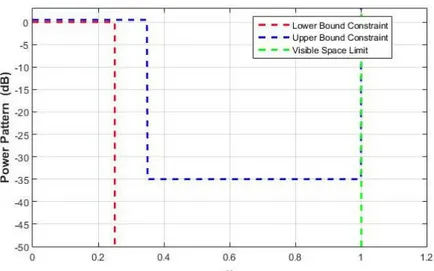
3.2 OPTIMAL SYNTHESIS OF A CIRCULARLY SYMMETRIC SOURCE RADIATING PENCIL BEAM: STATEMENT OF THE PROBLEM AND DESIGN PROCEDURE ... 58 3.3 OPTIMAL SYNTHESIS OF A CIRCULARLY SYMMETRIC SOURCE RADIATING SHAPED
BEAM.THE PROPOSED PROCEDURE ... 61 3.4 OPTIMAL SYNTHESIS OF A CIRCULARLY SYMMETRIC ONLY-PHASE
RECONFIGURABLE APERTURE SOURCE ... 70 3.4.1 NUMERICAL ASSESSMENT OF THE ONLY-PHASE RECONFIGURABLE CIRCULAR
SYMMETRIC CONTINUOUS APERTURE SOURCE ... 76
OPTIMAL DETERMINISTIC DISCRETIZATION OF THE CONTINUOUS SOURCE APERTURE INTO ISOPHORIC SPARSE ARRAY ... 85 4.1 INTRODUCTION TO THE OPTIMAL AND DETERMINISTIC DISCRETIZATION OF A
CONTINUOUS SOURCE ... 85 4.2 DENSITY TAPER FOR THE DISCRETIZATION OF A REAL CONTINUOUS SOURCE
INTO ISOPHORIC SPARSE LINEAR ARRAYS... 87 4.3 TWO-DIMENSIONAL DENSITY TAPER APPROACH FOR THE DISCRETIZATION OF A
8
ISOPHORIC SPARSE ARRAY. ... 105
4.5.1 RATIONALE OF THE DESIGN PROCEDURE ... 107
4.5.2 A NUMERIC EXAMPLE OF THE DETERMINISTIC SYNTHESIS OF THE SHAPED BEAM ... 111
4.5.3 COMPARISON WITH THE RECENT LITERATURE RESULTS ... 119
4.5.4 PHASE-ONLY RECONFIGURABLE CIRCULAR CONTINUOUS SOURCES DISCRETIZED INTO ISOPHORIC SPARSE RING ARRAYS ... 129
CONCLUSION AND FUTURE DEVELOPMENT ... 135
REFERENCES ... 139
List of Figures
Fig. 1.1-1: Active phased arrays in GIOVE-B satellite ... 14
Fig. 1.1-2: Multi-feed for beam concept ... 15
Fig. 1.1-3: Active antenna generating reconfigurable beam coverage ... 15
Fig. 1.1-4: Active DRA generating multibeam coverage ... 16
Tab. 1.1-3: Classification of the arrays antenna synthesis problems ... 19
Tab. 2.1-1: Antenna coefficients for the pencil beam ... 30
Fig. 2.1-1: Amplitude distribution of the linear array ... 30
Fig. 2.1-2: Comparison between the theoretical pattern and the CST pattern31 Fig. 2.1-3: Linear arrays with 11 radiating elements simulated in CST ... 32
Fig. 2.1-4: Asymmetric power mask constraints ... 32
Fig. 2.1-5: Amplitudes and phases of the optimal linear array ... 33
Fig. 2.1-6: Comparison between the theoretical pattern and the CST simulation pattern ... 33
Fig. 2.3-1 Assigned constrained power mask ... 38
Fig. 2.3-2: Theoretical power pattern satisfying the assigned power mask ... 38
Fig. 2.3-3: Zeros distribution on the complex plane ... 39
Fig 2.3-4: Radiation pattern of the synthesized array (blue line) and the comparison with the full wave analysis (black line) ... 40
Fig. 2.4-1: Example of factorable pattern: flat-top pattern along u-axis and pencil beam pattern along v-axis ... 41
Fig. 2.5-1: Multibeam coverage with reconfigurable beams ... 43
Fig. 2.5-2: Representation of the admissible solutions on space of all possible amplitude distributions ... 45
Fig 2.5-3: Shaped beam radiated by a fixed geometry array ... 46
Fig 2.5-4: The complete set of admissible amplitude (a) and phase (b) distribution ... 47
Fig. 2.5-5: Complete set of complex distribution which fit the shaped beam power mask and the unique real solution for the pencil beam pattern ... 48
Fig. 2.5-6: The nearest amplitude distribution for the shaped operative mode (blue line) and the pencil beam (dark line) ... 49
Fig. 2.5-7: Final amplitude distribution for the two operative modes ... 49
Fig. 2.5-8: Final phase distribution for the two operative modes: blue the phase for the shaped beam and in red the phase for the pencil beam ... 50
Fig. 2.7-1: Representation of the isophoric sparse array ... 52
Fig. 2.7-2: Gratin lobes for an array with regular lattice and an inter-element distance greater than half wavelength ... 53
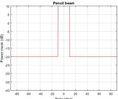
Fig. 3.2-1: Example of pencil beam power mask with a sidelobe of -20 dB ... 59
Fig. 3.2-2: Synthesis procedure of the continuous source radiating pencil beam ... 61
10
procedure ... 68 Fig. 3.3-5: Different amplitude and phase continuous aperture distribution
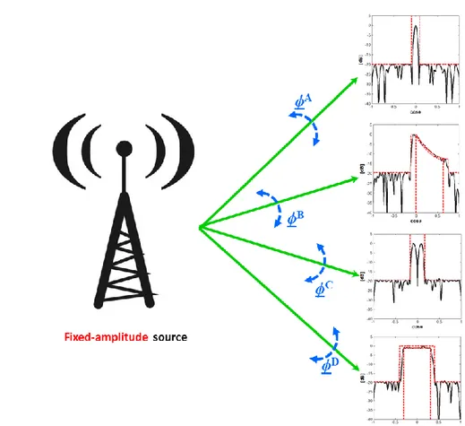
given the same shaped beam ... 70 Fig. 3.4-1: Only-phase reconfigurable source concept. Acting on the phase
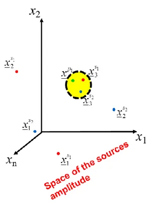
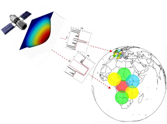
distribution different radiation patterns are available ... 71 Fig. 3.4-2: Representation of the solutions in the space of source amplitude 74 Fig. 3.4.1-1: Only-phase reconfigurable source covering the Earth surface
with a different kind of radiation pattern ... 76 Fig. 4.2-1: Cumulative distribution divided in N equal intervals ... 88 Fig. 4.2-2: Location of the radiating element according to the amplitude
current distribution ... 89 Fig. 4.2-3: Reference linear arrays with density taper approach ... 89 Fig. 4.3-1: Geometry of the problem considering the k-th ring ... 92 Fig. 4.3-2: Representation of cumulative discretization of the 2D density taper approach ... 96 Fig. 4.4-1: 3D representation of the cumulative function, blue and green curve
... 101 Fig. 4.4-2: Geometrical representation of a segment of the equilateral polygon dividing the continuous source ... 102 Fig. 4.4-3: Representation of the synthesis procedure for isophoric sparse
arrays radiating shaped beam ... 104 Fig. 4.5.1-1: Pictorial view of the m-th ring of a generic CRISA... 107 Fig. 4.5.1-2: Representation of S() in the complex plane (green color:
reference function; red color: discretized function) and as a curve in a three-dimensional space where the first and second coordinates are its real and imaginary parts, respectively, and the third coordinate is the radial coordinate (blue curve) ... 110
List of Tables
Tab. 1.1-1: Advantages of each active antenna configuration ... 17
Tab. 1.1-2: Disadvantages of each active antenna configuration ... 17
Tab. 1.1-3: Classification of the arrays antenna synthesis problems ... 19
Tab. 2.1-1: Antenna coefficients for the pencil beam ... 30
Tab 2.3-1: Amplitude and phase of the designed arrays radiating a shaped beam ... 39
1
Introduction
1.1
New antenna architecture and status of the arrays
antenna synthesis
The satellite communications in the last years have been the object of considerable changing in terms of performance and services offered to the customers. The new payloads require flexibility in terms of frequency/bandwidth or power allocation of coverage on the Earth surface, in order to have a product that satisfies the customers and the business needs. Flexible payload products are designed to reprogram a satellite mission when the spacecraft is already in orbit.
A satellite, which can reconfigure its characteristics, frequencies, coverages and/or power allocation, will allow the operator to follow in a very quick manner the evolving market request or access new businesses. Moreover, a flexible satellite opens plenty of opportunities for operators in their fleet, frequency rights and orbital slots management as well as allowing for the progressive deployment of the associated ground segments and gateways. Beam reconfiguration permits satellite to track mobile terminals. For example, in the marine industry, a beam can be re-configured to seamlessly track the progress of a terminal across an ocean, without having to lease multiple beams to cover the relevant regions.
Quantum satellite, manufactured by Airbus, will be the first generation of universal satellites able to serve any region of the world and adjust to new business needs without the user procures and launches a new satellite. Quantum will be able to adjust its coverage and capacity to suit customers’ needs as and when they change. In addition, the re-configurability is not only an essential feature in the new telecommunications satellite. Also in the radar
14
sector it is a crucial aspect to achieve a reconfiguration of the radiative properties in order to have a product which can be adapted to several cases.
Regarding the request of flexibility (re-configurability in terms of spot beam shape, steerable antennas and high gain), the DRA (Direct Radiating Array, see Fig. 1.1-1) may represent an attractive alternative to the conventional well-known solution based on single or multi-reflector system. All the reflector solutions based on single feed per beam configuration or multiple feed per beam configuration are not able to meet the requested re-configurability.
Fig. 1.1-1: Active phased arrays in GIOVE-B satellite
The main limitation for the classical architectures with single feed per beam is the impossibility to reconfigure the antenna during the lifetime of the satellite, in other words, to follow the changes of the user traffic request in terms of coverage footprint (beam pointing/steering), EIRP (beam power), and frequency plan (beam frequency). The second limitation is the fact that, for generating contiguous spot coverage, the satellite should embark more reflectors with large dimensions and consequently it has an impact on the overall mass and volume (critical aspect for the satellite). The alternative solution, multi-feed per beam that represents still the State of the Art, solves
the mass and volume issues but it is in any case not completely reconfigurable. In the multi feed per beam antenna more feeds participate for generating a spot beam on the Earth surface (see Fig. 1.1-2)
Fig. 1.1-2: Multi-feed for beam concept
The active antenna is the suitable candidate architecture to solve the mentioned problems and to design an antenna with maximum flexibility. Active antennas allow to re-configure the footprint coverage by the pointing capabilities, matching the possible modification of the SATCOM mission scenario due to longitude satellite position modification or to a new coverage shape or position, see Fig. 1.1-3.
16
Active antennas allow setting the EIRP (Equivalent Isotropic Radiated Power) performance of each beam matching the user traffic request sharing the power available from the radiating elements amplifiers. Moreover, active antennas allow generating multiple beams coverage with continuous footprint by means of the same aperture minimizing the complexity of the satellite layout.
Fig. 1.1-4: Active DRA generating multibeam coverage
The active antenna family is constituted by several antenna architectures as:
Arrays Fed Reflector (AFR) – focused or defocused Direct Radiating Arrays (DRA)
Imaging Confocal Arrays (ICA) Active Discrete Lens (ADL)
Tab. 1.1-1 and Tab. 1.1-2 resume shortly the main advantages and disadvantage between the main active antennas configuration which are under investigations by ESA in the last ten years.
As it can be noted all these configurations are based on the use of a DRA integrated with a single o multi-reflector system or in stand-alone condition. The techniques for the design of arrays in regular o irregular lattice are shared from all the active antennas.
Tab. 1.1-1: Advantages of each active antenna configuration
18
In the family of the DRA one particular class of antenna is very appealable and promising for the new onboard missions: the isophoric sparse DRA, an arrays with an equal signal amplitude at each radiating element which are not accommodate in a periodic lattice. The isophoric sparse arrays permits to optimize the efficiency of the SSPAs (Solid State Power Amplifiers) allowing them to work at the same working point. In addition, this kind of antenna architecture guarantees the performance (bandwidth and SLL) which are comparable with the full populated periodic arrays by using a smaller number of elements. The reduction of active elements inside the antenna permits to reduce the complexity of the antenna, of the cost and of the overall weight.
The mentioned above requests from the new business market give the opportunity to the scientific community to investigate new arrays antenna architectures and encouraging the development of new synthesis techniques as demonstrated by several publications on the subject.
Considering the kind of radiated pattern which will be designed and the available degrees of freedom a very large number of synthesis problems can be identified. Executing an excursus of the literature on the arrays synthesis problems, a possible classification can be carried out as the one reported in Tab. 1.1-3 where the rows refer to the kind of radiated pattern (pencil beams, difference patterns, shaped patterns, steerable patterns, reconfigurable patterns), while the columns refer to the available degrees of freedom [just excitations, constrained excitations (binary or quantized), just locations, both excitations and locations, phase-only, combinations of the above].
Tab. 1.1-3: Classification of the arrays antenna synthesis problems
Due to intrinsic simplicity of the problems, a large number of contributions in the literature ensuring the achievement of an optimal solution is available for a fixed geometry and arbitrary excitation (corresponding the first column of Tab. 1.1-3 ).
In particular, optimal solutions have been designed for the synthesis of pencil beams or difference beams subjected to full arbitrary bounds on the sidelobe level by means of arbitrary geometry arrays (including linear, planar, and conformal arrays, the only constraint being the fact that positions of the elements are fixed in advance).
While previous analytical results exposed were limited to the case of an equal level of the sidelobes [5-7], the approach in [8-11] by Isernia et all suggests that the problems of maximizing the field (or its slope) in a given direction while keeping the field below given values can be conveniently reduced to Convex Programming [8-10] or even to Linear Programming [11] problems and therefore a unique global optimum exists for such a class of problems. In addition, this approach is applied to the maximization of directivity subject to given constraints for the sidelobes. As a consequence, these classes of canonical problems are solved. An important result achieved by these solutions is the absence of global optimization algorithm, characterized often by a very high computational cost.
Optimal solution strategies have been designed for the optimal synthesis of shaped beams with uniformly-spaced one-dimensional arrays [12] (wherein an effective procedure for general arrays is also devised).
20
Unlike the previous cases, the literature presents much less theoretical results for the classes of arrays synthesis problems where the locations are the unknowns. In fact, in all cases wherein the locations of the radiating elements have to be determined the radiated field depends in a non-linear manner from the unknowns and therefore a more difficult relationship has to be considered in the synthesis.
The interesting theoretical question arises of how to tackle these classes of problems in such a way to achieve a kind of optimal solution to the design problem at hand without exploiting global optimization procedures, wherein by ‘optimal’ it means
“an arrays able to fulfill given design goals by exploiting the minimum number of elements (or the minimum aperture size, or the minimum number of other resources) or, equally, to optimize given performances for a fixed number of elements (or fixed aperture dimensions, or fixed other resources)”.
It is worth noting that the need for using possibly deterministic procedures is due to a number of reasons. The main ones being that of avoiding the computational burden of the global optimization algorithms and the fact that local (or quasi-analytical) solution procedures allow one to better understand and check the expected properties of the different solutions which can be devised. In [17] and in [21] the deterministic procedures for the synthesis of uniform-amplitude linear sparse arrays radiating a pencil beam or a shaped beam are discussed. These approaches include the well know density taper procedure. These methods exploit an analytical formulation of the problem and the convex programming routine achieving the optimal solution without recurring to global optimization.
A more general problem, with an increased number of degrees of freedom, is the case of the synthesis using both locations and excitations of the elements of the array. The goal is generally that of exploiting the additional degrees of freedom deriving from the possibility to choose locations in order to save a number of elements, thus saving costs. The problem, which is of interest in radar applications as well as in many other
cases, has attracted the interest of a number of researchers, giving rise to solution procedures ranging from global optimization, hybridization of global and local procedures, to the use of the so-called ‘Matrix Pencil Method’ [30] and its modifications [31-32], up to the exploitation of the theory of ‘compressive sensing’ [33]. Hybridizations amongst all these different methods have also been considered.
Another very interesting class of problem of large applicative interest is the one wherein one tries to synthesize two, or more, different patterns by means of excitations having a common amplitude distribution for the different modalities, so that reconfigurability is achieved by simply acting on phase distributions. In the last years several publications ([34-35]) appears for the case of linear arrays but a gap is presented for the case planar arrays able to be reconfigured in terms of radiation patterns (pencil and shaped beam). The few synthesis procedures for the reconfigurable planar are not completely deterministic or they are sub-optimal solution ([36]). In order to fill up this gap, this Ph.D. thesis introduces a deterministic procedure design instead of stochastic optimization to deal with the open problems for the synthesis of isophoric sparse arrays organized in concentric rings which are able to be reconfigurable acting only in the phase distribution.
The next paragraph reports the novelty included in this thesis work and how the chapters are organized.
1.2
Objective, motivation and outline of the thesis
The aim of this thesis is to consider an open point in the array synthesis that concerns the optimal synthesis of reconfigurable isophoric sparse arrays organized in concentric rings. In order to fulfill this need a preliminary step is required in order to solve another open problem in the arrays synthesis that is related to the optimal synthesis of shaped beams radiated by a concentric ring isophoric sparse array architecture. These two array synthesis problems have a common kernel which is represented by the need to use a full deterministic procedure for the discretization of a reference complex source into an isophoric sparse array.
22
The sparse array antennas, arrays whose elements are located over an aperiodic layout such to fulfill given radiation requirements, represent an important topic for antenna designers. This is shown by a large number of both ‘classic’ ([2]-[4]) and more recent ([13]-[26]) contributions.
Such a large interest is due to the advantages offered by these systems with respect to equispaced arrays. In fact, for a fixed aperture size, sparse arrays allow decreasing the number of elements without significantly affecting the beamwidth [19]. Such a lowering, in turn, mitigates mutual-coupling issues (due to the increased value of the average inter-element spacing) and it implies a reduced cost, weight, and complexity of the feeding network [2]. Moreover, the aperiodicity of the layout allows reducing grating lobes in the radiation pattern and hence an improvement of performance in terms of both sidelobes level (SLL) and bandwidth [17]. Finally, aperiodic arrays may allow a SLL reduction without resorting to an excitation-amplitude tapering [22]. The last advantages above led over the years to the large diffusion of a particular kind of sparse arrays: the so-called ‘Isophoric’ Sparse Arrays (ISA) [17]-[26], aperiodic arrays having a constant excitation amplitude over the whole aperture. This feature allows the feeding power amplifiers to operate at their point of maximum efficiency and it greatly simplifies the beam forming network [19],[22].
Amongst all ISAs planar architectures, Concentric Ring Isophoric Sparse Arrays (CRISAs), isophoric sparse arrays whose elements are located onto concentric rings, appear being the most convenient ones due to their capability of uniformly spreading the antenna energy over all azimuth directions [18],[21]-[26]. In fact, CRISAs constitute one of the usual choices to realize the satellite multibeam coverage of Earth [18],[23],[24].
Of course, isophoric sparse arrays configuration has also its disadvantages. The most critical drawback is related to the corresponding synthesis procedures. In fact, since the elements’ locations are an unknown of the design problem, the synthesis is unaffordable through Convex Programming (CP) procedures of the kind presented in [27]. Therefore, as done for instance in [13]-[16], the antenna designers often recur to Global Optimization (GO) procedures. However, due to their high computational
weight, GO techniques practically result unsuitable for the synthesis of isophoric sparse arrays composed by a very large number of elements. To overcome such difficulties, the following two-steps procedure has been recently devised for the design of Linear Isophoric Sparse Arrays (LISA) and Concentric Ring Isophoric Sparse Arrays (CRISAs) [17]-[24]:
1. Identify a Reference Continuous Aperture Source (RCAS) fulfilling ‘at best’ the radiation requirements at hand;
2. Derive the arrays layout as a discretization of the RCAS.
This procedure allowed to outperform previous approaches [17]-[24]. In fact, a number of well-assessed methods already exist to perform step 1 ([28], [29]) and, only in the ‘pencil beams’ case, step 2 ([2], [17], [18], [22]-[24]). Unfortunately, much fewer alternatives to perform step 2 are available in the ‘shaped beams’ case. The reason of such lack derives from a simple circumstance. The RCASs generating sufficiently narrow pencil beams are real functions [28], in the shaped beams case they result to be complex ones [29]. This issue, which drastically complicates step 2 [23], has been recently solved for the case of LISAs (Linear Isophoric Sparse Arrays) in [21] but still results unsolved for CRISAs. In fact, the unique approach currently available to perform step 2 in the CRISAs case is the ‘rough’ one in [23], which bypasses the problematic of the RCAS’s complexity by:
a) Identifying the elements’ locations by applying the technique presented in [18] only to the RCAS’s amplitude;
b) Assigning to each arrays element an excitation phase equal to value assumed in its location by RCAS’s phase.
This procedure neglects the fact that, as discussed in [21], the arrays elements locations must be a function of both the RCAS’s amplitude and phase distributions, and hence its performance is considerably improvable. On the other side, beyond [23], the unique contribution addressing the synthesis of CRISAs in the shaped beams case is [16]. It relies on GO and hence it is exploitable only in case of CRISAs composed by a low number of elements. In the attempt of filling such a gap, this thesis proposes a new approach to
24
the mask-constrained power synthesis of shaped beams through CRISAs. The technique can be seen as the extension of the approach in [21] to the case of ring symmetric arrays layouts and it results fast and effective even in case of arrays composed by a large number of elements.
After the definition of the deterministic procedure for the optimal synthesis of the isophoric sparse concentric ring arrays radiating a shaped beam, the introduced method can be used in the synthesis of only phase reconfigurable isophoric sparse concentric ring array. The only-phase isophoric sparse concentric ring arrays are a particular class of the reconfigurable antennas. In particular, the reconfigurability, i.e., the possibility to change the kind of radiating pattern (pencil beam, shaped beam, cosecant beam, fan beam, etc), is obtained only by changing the phase on the array while keeping the isophoricity requirement in terms of amplitude. This constraint permits to have several advantages at the satellite level. In facts, the reconfigurability permits to change the radiation modality in according to the load on the Earth surface (large beam in low-density traffic zone and small beams in the high-density traffic region). Moreover, the only-phase reconfigurability in active phased arrays can be implemented in very easy way without to increase the number of components and the complexity of the arrays (the same phase shifter of the phased arrays can be reprogrammable changing the phases on the antenna aperture).
To perform the synthesis of an only-phase reconfigurable isophoric sparse concentric ring arrays the following steps are required:
1. Identify a Reference Continuous Aperture Source that is an only-phase reconfigurable continuous aperture.
2. Derive the arrays layout as a discretization of the only-phase reconfigurable continuous aperture exploiting the synthesis procedure implemented for the shaped beam case.
Regarding point 1 a new synthesis technique for continuous source aperture will be derived and presented in this thesis.
The novelty of this thesis work respect to the state of the state-of-the art is the definition of a full deterministic and fast procedure that exploits at the
best the characteristic of a planar complex source used as reference for the array synthesis. The introduced method does not have any type of limitation in terms of array dimension and therefore in terms of variable that are to be addressed. The proposed method permits also to define a complete workflow for the synthesis of only-phase reconfigurable source and its optimal discretization to design the isophoric sparse array organized in concentric rings.
In summary, in the thesis the following arguments will be dealt with: i. State-of-the-art on the power mask constrains synthesis of arrays
radiating pencil beam, shaped beam and reconfigurable beams ii. Optimal synthesis of a continuous source for the synthesis of pencil
beam, shaped beam and the introduction of the synthesis procedure of continuous source for the only-phase reconfigurable beams exploiting at the best the optimal synthesis of pencil and shaped beams.
iii. Synthesis of isophoric sparse concentric ring arrays radiating pencil beam, shaped beam and reconfigurable beams. In this chapter the starting point will be the presentation of the results present in the literature for the case of pencil beam (1-D and 2-D problem) and shaped beam (only 1-D was literature) in order to derive the synthesis of shaped beam and only phase reconfigurable beams for the 2-D case (objective of the work).
26
2
State-of-the-art on the power mask
constraints deterministic synthesis
2.1
Optimal synthesis of linear arrays with fixed geometry
radiating pencil beam
In this chapter a survey on the state of the art for the synthesis of linear and planar arrays with fixed geometry able to radiate pencil beam, shaped beam and/or reconfigurable beam is performed. As it just explained, this kind of synthesis problem is simpler than the other ones which were presented in the introduction of this thesis (i.e. where the location of the elements are the unknowns). This survey is carried out in order to acquire the methodologies used for the optimal research of the synthesis problem solutions and to well understand what is needed for the synthesis of isophoric sparse arrays radiating reconfigurable beam.
In the case of linear uniformly spaced arrays with constant sidelobe levels globally optimal solutions to the pencil beam problem are obtained by exploiting the properties of the Chebyshev polynomials ([37], [38]). Once the number of elements, the uniform spacing, and the SLL have been fixed, these arrays exhibit a larger directivity than conventional Chebyshev arrays, provided the number of elements exceeds a minimum value depending on the SLL and element spacing. However, these “modified” Chebyshev polynomials also exhibit a larger beamwidth. The drawback associated to these approaches is that they are unable to deal with non-uniform, asymmetric, sidelobes pattern. In a few of words, they are not able to shape the sidelobes to reduce the arrays radiation on angle range where an undesired interference is present. A second important limitation in the modified Chebyshev approaches is that they can only work with arrays having a
uniform spacing (on a line or on a plane) and with identical radiating elements.
In [9] Isernia et all provided an improvement and the problem of determining the excitations of a given set of arbitrarily positioned sources so as to produce a far-field intensity that is maximum in a prescribed direction and subjected to completely arbitrary upper bounds elsewhere was tackled. The formulation includes any kind of fixed geometry arrays and can be naturally applied to considering mutual coupling.
In particular, considering a set of N radiating element, each characterized by a proper radiation behavior,𝑖(𝑟), the total radiation pattern of the array can
be written as:
𝐸(𝑟) = ∑ 𝑎𝑖𝑖(𝑟) 𝑁
𝑖=1
(1)
where the 𝑎𝑖, 𝑖 = 1, … , 𝑁 are the complex excitations of the N radiating
elements and they represent the unknowns of the problem. An important consideration is required. The expression (1) relates the desired far field with the unknown excitations in linear manner. This relationship permits to consider the synthesis problem with fixed geometry as the simpler one problem.
Therefore, the synthesis problem can be formulated as follows:
“Determine the set of complex excitations {𝑎𝑖, 𝑖 = 1, … . 𝑁} such that
|𝐸 (𝑟0)| 2 = |∑ 𝑎𝑖𝑖(𝑟0) 𝑁 𝑖=1 | 2 (2)
is maximum and respects the constraints
|𝐸(𝑟)|2 = |∑ 𝑎𝑖𝑖(𝑟) 𝑁 𝑖=1 | 2 ≤ 𝑆𝐿𝐿(𝑟) (3)
where SLL(r) is the non-negative arbitrary function which defines the sidelobes level in the whole observation space and 𝑟0 is the antenna point
Recurring to the bandlimitedness properties of the far field, considering a sufficiently dense distribution of sampling points over the observation domain S and without any loss of degrees of freedom, the problem can be formulated as:
Determine the complex excitation (𝑎𝑖 = 𝑥𝑖 + 𝑗𝑦𝑖 , 𝑖 = 1 … 𝑁) such that
−𝑅𝑒𝑎𝑙(𝐸 (𝑟0)) is minimum (4)
with the following constraints
𝐼𝑚𝑎𝑔 (𝐸 (𝑟0)) = 0 (5) { |𝐸 (𝑟1)| 2 ≤ 𝑆𝐿𝐿(𝑟1) : |𝐸 (𝑟𝐿)| 2 ≤ 𝑆𝐿𝐿(𝑟𝐿) (6)
where 𝐿 is the number of observation points of the dens grid in the domain. In equation (4) the sign minus is due to the fact that the reference phase of the field for direction 𝑟0 is .
Since |𝐸 (𝑟1)| 2
is a positive semidefinite quadratic form (a hypercylinder) as a function of the complex excitations, each constraint in (6) define a convex set in the space of the unknowns. Moreover, the constraint of (5) is linear in terms of the excitation so that it also defines a convex set (an hyperplane) in the space of the unknowns. The intersection of convex sets in turn is a convex set, and therefore the (5) and (6) define a convex set. Finally, the objective function (4) is a linear function of the unknowns and consequently the overall problem is equivalent to the minimization of a linear function in a convex set C. This kind of optimization problem has been analyzed in operations research, and it can be demonstrated that it admits a unique minimum value, which is the global optimum, and it is achieved in a single point or in a connected (convex) subset of C.
In order to assess this fast deterministic optimal procedure, a numerical example is proposed. A linear arrays radiating a pencil beam with a “null-to-null” beamwidth of 29.5 degrees and a sidelobe level of -30 dB is designed
and verified by means of a virtual demonstrator in CST (Computer Simulation Technology).
Performing the synthesis of the linear arrays with equally spaced elements, /2 at the frequency of 30 GHz, the following eleven normalized coefficients are obtained, see Tab. 2.1-1 and Fig. 2.1-1.
Id element Amplitude [dB] Phase [deg]
1 -7.38 0 2 -4.42 0 3 -2.39 0 4 -1.02 0 5 -0.26 0 6 0 0 7 -0.26 0 8 -1.02 0 9 -2.39 0 10 -4.42 0 11 -7.38 0
Tab. 2.1-1: Antenna coefficients for the pencil beam
Fig. 2.1-2 reports the comparison of the radiation pattern between the theoretical pattern achieved implementing the deterministic procedure and the virtual demonstrator pattern achieved by means of a full wave simulation in CST. In order to have a more accurate synthesis, the mutual coupling effect between the radiating elements is considered including in the deterministic procedure the radiation pattern of the feed in embedded condition (the radiation pattern radiated by the only central element of the array constituted by 11 radiating feeds). As demonstrated by Fig. 2.1-2, the results of the optimal synthesis are confirmed by the full wave analysis in CST; a good agreement is obtained validating the design procedure.
Fig. 2.1-2: Comparison between the theoretical pattern and the CST pattern
Fig. 2.1-3 shows the linear arrays modeled for the full wave analysis. Eleven rectangular waveguides with an inner dimension of 8.36x4.132 mm are used. A ground plane is considered in order to avoid the appearance of the back lobe.
Fig. 2.1-3: Linear arrays with 11 radiating elements simulated in CST
After the validation of the synthesis procedure for the case of uniform sidelobe level, a second example is carried out considering the case of radiation pattern with asymmetric sidelobes. Fig. 2.1-4 shows the normalized asymmetric power mask constraints for the synthesis. The “null-to-null” beamwidth is 12.5 degrees. Implementing the synthesis procedure, the minimum number of radiating elements to meet the requirements is 21.
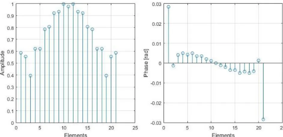
Fig. 2.1-5 reports the amplitudes and phases of the optimal linear arrays synthesized with the proposed deterministic procedure.
Fig. 2.1-5: Amplitudes and phases of the optimal linear array
Fig. 2.1-6 shows the radiation patterns of the theoretical optimal solution and the simulated pattern evaluated with CST. The agreement between the two patterns demonstrates, once again, the capability of the procedure to design in a fast and deterministic way the optimal solution for the assigned constraints. The CST simulation is performed considering as radiating element a rectangular waveguide working at 30 GHz. The arrays is composed of 21 rectangular waveguides with an inter-element distance of /2.
Fig. 2.1-6: Comparison between the theoretical pattern and the CST simulation pattern
2.2 Optimal synthesis of planar arrays with fixed geometry
radiating pencil beam
In an equivalent manner as the linear case introduced in the previous section, also for an arbitrary fixed planar arrays geometry the optimal synthesis of a pencil beam pattern with arbitrary sidelobe constraints can be dealt with a Convex Programming problem. In fact, all constraints on the sidelobes are convex in terms of the excitations, and the cost function to be optimized turns out to be convex in both cases where one wants to maximize the field in the target direction [9] as well as in the case one wants to optimize the directivity for a given peak Side Lobe Level (SLL) ( for an assigned minimum separation between the peak lobe and sidelobes [11]). As a consequence of convexity inside the problem definition, in both cases, the globally optimal solution can be determined without the need of global optimization techniques.
2.3 Optimal synthesis of linear arrays with fixed geometry
radiating shaped beam
Differently from the pencil beam pattern described in the previous section, in the case of a shaped beam pattern the constraints for the power pattern are furnished in terms of lower bound (LB) and upper bound (UB). The UB and LB are functions of the observed angles, and they represent the functions where the power radiation pattern can lay. The upper and lower bound compose the mask power constraints for the desired radiation pattern. For a linear arrays with fixed geometry the synthesis problem for the shaped beam can be synthesized in the following sentence:
“Define the set of 𝑁 complex excitations such that
𝐿𝐵(𝜗) ≤ |𝐸(𝜗)|2 ≤ 𝑈𝐵(𝜗) ”
In this case the problem of synthesis and optimization is more complex with respect to the pencil beam case. In fact, the problem is not a linear one in terms of the unknowns but, specifically, it requires to solve a set of non-linear inequalities.
In [12] Isernia and Bucci have defined a general criteria to establish a priori if a given antenna can radiate or not a pattern according to the assigned power mask. To ascertain a priori the feasibility of an assigned power synthesis problem, the mathematical characteristics of a squared amplitude radiated field distribution are exploited.
As can be easy to demonstrate, for a linear arrays with N equispaced elements along the z-axis the arrays factor can be represented with the following square amplitude function: 𝑃(𝑢) = 𝑐0+ ∑[𝑐𝑝cos(𝑝𝑢) + 𝑠𝑝sin(𝑝𝑢)] = 𝑁−1 𝑝=1 ∑ 𝑃(𝑢𝑝)𝐷2𝑁−1(𝑢 − 𝑢𝑝) 𝑁−1 𝑝=1−𝑁 (7)
where u = bdcos(ϑ), up =2N−12 and 𝑑 is the separation between adjacent
antennas. The formula (7) can be generalized with the following expression:
𝑃(𝜗, 𝜑) = ∑[𝐷𝑝𝑝(𝜗, 𝜑)] 𝑇
𝑝=1
(8)
Due to the representation of the power pattern of a linear arrays with fixed geometry obtained in (8), it is easy to show which conditions have to be satisfied in order that the pattern respects the power mask constraints. In fact, equation (8) represents all possible patterns radiated from a given class of sources, a necessary condition for the existence of a pattern fulfilling the given constraints is that it satisfies the following system of functional linear inequalities expressed in the variable Dp:
{ ∑[𝐷𝑝𝑝(𝜗, 𝜑)] 𝑇 𝑝=1 ≤𝑈𝐵(𝜗, 𝜑) ∑[𝐷𝑝𝑝(𝜗, 𝜑)] 𝑇 𝑝=1 ≥𝐿𝐵(𝜗, 𝜑) (9)
As demonstrated in [39] the function P(ϑ, φ) is a bandlimited function with a band of 2a and consequently the equation system (9) can be discretized in a suitable dense manner so that a simplification on the system is obtained:
{ ∑[𝐷𝑝𝑝(𝜗𝑖, 𝜑𝑗)] 𝑇 𝑝=1 ≤𝑈𝐵(𝜗𝑖, 𝜑𝑗) ∑[𝐷𝑝𝑝(𝜗𝑖, 𝜑𝑗)] 𝑇 𝑝=1 ≥𝐿𝐵(𝜗𝑖, 𝜑𝑗) (𝑖 = 1 … 𝑀1, 𝑗 = 1 … 𝑀2) (10)
The mathematical system (10) is a common linear inequality system expressed in the variable Dp. The solution of this class of problem is well known and it
is equivalent to assess the existence of a feasible point for a linear programming problem. As demonstrated, this existence criterion requires the solution of a linear problem which is clearly simpler than the initial system of functional inequalities. It is obvious that solving a system of linear inequalities is faster than solving a system of functional inequalities with the same number of unknowns. Another aspect is that the existence criterion is able to work with any constraints if they are expressed in terms of linear functions of the squared amplitude distributions. Moreover, any type of constraints which is convex with respect to square amplitude distribution can be added at the initial equation system without affecting the possibility to find a solution and defining the feasibility point. Due to the fact that T ≥ 2C, where C is the number of complex degree of freedom of the field, the set of feasible pattern is a subset of the full space determined by (9) and therefore the fulfillment of (10) is usually necessary but not sufficient for the existence of a pattern satisfying the mask constraints. However, there is a special case where the existence criterion is well necessary and sufficient and it is the case of linear array.
Regarding the linear arrays with fixed geometry, the equation (8) can be specialized in the following one:
𝑃(𝑢) = ∑ [𝐷𝑝𝑒𝑗𝑝𝑢] 𝑁−1
𝑝=−𝑁+1
𝑤𝑖𝑡ℎ 𝐷𝑝= 𝐷∗𝑝 (11)
Where the power pattern is a real function and therefore being the 𝑃(𝑢) a non-negative trigonometric polynomial and, according to the Fejér-Riesez theorem [40], the 𝑃(𝑢), it can be factorized as
Where
𝐹(𝑢) = ∑[𝐹𝑝𝑒𝑗𝑝𝑢] 𝑁−1
𝑝=0
(13)
which can be considered as an arrays factor of a linear arrays with 𝑁 radiating elements. Therefore if exists a 𝑃(𝑢) as expressed in (11) which satisfies the power mask constraints assigned to the antenna designer, it certainly exists a set of coefficients able to radiate this pattern. An important aspect related to the factorization of the 𝑃(𝑢) need to be addressed. In particular, the factorization is not unique and the flipping of the zeros which lying outside the real axis of the complex u plane permits to identify 2𝑁0 (𝑁0 is the number
of zeros not lying on the unit circle) distinct sets of coefficients able to radiate 𝐹(𝑢).
As described above the existence criterion, for the specific case of linear arrays with fixed geometry, is a necessary and sufficient criterion able to determine if a pattern lying in a specific power mask can be radiated by an arrays of a given size. The described synthesis method can be considered as a modified case of the classical pattern synthesis method based on the “zero location” (see [41]).
The possibility to identify 2𝑁0 possible equivalent solutions gives the
opportunity to select the most convenient solution according to some project constraints.
To give a prove of the goodness of this synthesis procedure and to verify the performance an example is carried out.
Fig. 2.3-1 reports the constrained power mask for the synthesis of a linear arrays with fixed geometry, in red the upper bound constraint and in blue the lower bound constraint. The power mask asks to synthesize a shaped beam with:
a ripple maximum of 1.5 dB,
a flat region in the angles −1 ≤ 𝑢 ≤ 1
-20 dB of SLL and a suppression region in |1.7≤ 𝑢 ≤ 2| with a SLL of -30 dB
Fig. 2.3-1 Assigned constrained power mask
Performing the existence criterion the power pattern which lying in this power mask is found as shown in Fig. 2.3-2. The criterion permits to define the minimum number of elements in order to satisfy the assigned power mask.
Fig. 2.3-2: Theoretical power pattern satisfying the assigned power mask
As described in the previous part of this section, the theoretical solution is not a unique solution but 2N0 possible equivalent ones are available. For this
specific example N0 = 10 and therefore 1024 equivalent solutions are valid to
satisfy the request of the problem in terms of square amplitude far field, see Fig. 2.3-3.
Fig. 2.3-3: Zeros distribution on the complex plane
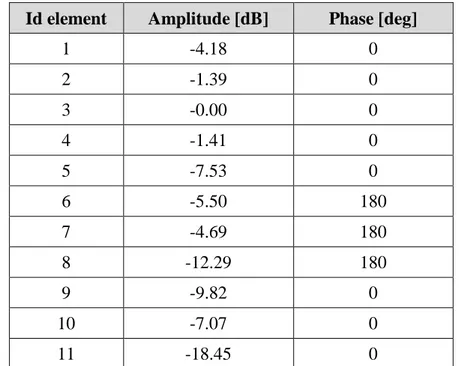
Tab 2.3-1 reports the set of the synthesized complex coefficients for the linear arrays able to fulfill the constraints.
Id element Amplitude [dB] Phase [deg]
1 -4.18 0 2 -1.39 0 3 -0.00 0 4 -1.41 0 5 -7.53 0 6 -5.50 180 7 -4.69 180 8 -12.29 180 9 -9.82 0 10 -7.07 0 11 -18.45 0
Tab 2.3-1: Amplitude and phase of the designed arrays radiating a shaped beam
Fig 2.3-4 reports the radiation pattern calculated by means of a full wave simulation in CST. It can be noted a good agreement between the pattern calculated with the existence criterion and the one calculated with the full wave simulation.
Fig 2.3-4: Radiation pattern of the synthesized array (blue line) and the comparison with the full wave analysis (black line)
2.4 Optimal synthesis of planar arrays with fixed geometry
radiating shaped beam
In the previous paragraph the feasibility criterion is introduced for the synthesis of a linear arrays with fixed geometry able to radiate a shaped beam. As demonstrated for the one-dimensional case the feasibility criterion is at the same time necessary and sufficient. In fact the feasibility criterion permits to assess a linear arrays can satisfy the power mask constraints (necessary condition), or not, and then by means of the factorization, it permits to synthesize the complex coefficients (sufficient condition) of the arrays in order to radiate the desired far-field. For the two dimensional case there is an important difference respect the one-dimensional case. In fact for the two dimensional case a factorization rule analogous to the one for 1-D arrays does not exist. 𝑃(𝑢, 𝑣) = ∑ ∑ 𝑃(𝑢𝑝)𝐷2𝑁−1(𝑢 − 𝑢𝑝) 𝑀−1 𝑝=1−𝑀 [𝐷2𝑀−1(v − 𝑣𝑝)] (14) 𝑁−1 𝑞=1−𝑁
In fact, if the equation (14), which is an explicit form of equation (8) and it represents the power pattern of a NxM equispaced element array, satisfies the power mask constraints the feasibility criterion is necessary. But,
at the same time it is not possible to factorize the power patter and therefore a feasibility solution is not available and the criterion is not sufficient.
However, there exists a particular exception: power pattern mask which can be factorized as product of two masks along the principal axis, Fig. 2.4-1. In this case, for each of the principal cuts the procedure presented for the linear case can be used. It has to be noted that in this cases the criterion is sufficient but not necessary. In fact, while it provides a solution to the synthesis, it looks for factorizable excitations, which represent a subset of all the possible ones.
Nevertheless, wherein the sufficiency is not guaranteed, the criterion can be used to discard those problems which are certainly unfeasible.
Fig. 2.4-1: Example of factorable pattern: flat-top pattern along u-axis and pencil beam pattern along v-axis
In the "feasible" cases, the pattern furnished by the criterion will be quite certainly not factorizable. However, exploitation of representation (14) allows to state the power synthesis problem in a linear space as small as possible, thus drastically reducing the set of possible patterns with respect to the much larger set of all generic functions compatible with the constraints. In such a way, an effective synthesis procedure can be devised.
To this end, let us note that the operator which relates the unknown excitations to the squared amplitude distribution of the radiated field can be regarded as a quadratic operator, Q, acting on the vector, a, of the real and imaginary parts of the excitations coefficients. Defining with 𝑃 the set of realizable power pattern furnished from the existence criterion. The synthesis procedure can be seen as the minimization of the distance between 𝑄(𝑎) and the convex set of patterns 𝑃
𝛩(𝑎, 𝐷) = ||𝑄(𝑎) − ∑ 𝐷𝑝
𝑇
𝑝=1
𝛹𝑝(𝜗,) || 14. 𝑐
wherein 𝐷 is the vector of the 𝐷𝑝 coefficients.
2.5 Linear arrays with fixed geometry synthesis radiating
reconfigurable beam
The design of a single antenna aperture able to radiate different kind of beams is a very interesting problem in the sector of the antenna synthesis due to the large number of application from remote sensing, radar antenna or satellite communications. The satellite communication is the principal field of application where the request of reconfigurable single aperture antenna is demanding. In fact, the satellite operators increase in the last years the request of reconfigurable beams in order to adapt the beam dimension in according to the traffic load in a specific area of the Earth as shown the Fig. 2.5-1 where large beam and very small beam are used in order to contrast the load traffic requests.
As described in the introduction of this thesis, among the different kind of antenna technological solutions, the phased arrays antenna is the solution which permits to implement this kind of flexibility because they can be controlled by means of a completely electronic technique and in a very fast manner. The problems which affect the phased arrays is that regarding the complexity in the BFN (beam forming network) design. In order to maintain the cost and the complexity of the phased arrays architecture, a solution is to realize the reconfigurability acting only in the phase, the excitation sets corresponding to the various patterns differ only in their phase distributions. This has a great advantage because new hardware is not required and, moreover, using in the BFN a single power-divider network it makes the solution cheaper and more efficient than those which dynamically modify the amplitude of the weight coefficients.
Fig. 2.5-1: Multibeam coverage with reconfigurable beams
The main drawback of the only-phase reconfigurability concerns the intrinsic difficulty in solving the corresponding synthesis problem in an optimal fashion, i.e., in fulfilling given design goals by exploiting the minimum number of elements or optimizing given performances for a fixed number of elements. Indeed, the ‘common amplitude’ requirement on the excitations results in non-linear and non-convex constraints, which implies considerable additional difficulties in the development of effective synthesis procedures.
In the literature, the problem has been approached both using the so-called ‘alternating projections’ technique [42]-[44] and exploiting global optimization strategies [45]- [49]. Because of the non-linear constraints and the arising non-convex sets involved in the alternating projection technique, the optimization procedure can be trapped into local minima far from the actual optimal solution. Differently, for ‘global optimization’ algorithm the computational cost increases with the problem size.
In the recent years A. F. Morabito et al. proposed in [50] an effective approach for the linear arrays only-phase reconfigurable antenna making use of only deterministic procedure. The approach benefits from theoretical results and optimal solutions available in the separate synthesis of pencil and shaped beams with fixed geometry introduced in the previous section of this chapter. This approach is very interesting to face in order to find a first deterministic valid strategy which will be modified to solve the problem of the synthesis of isophoric sparse only-phase reconfigurable array, which is the subject of this thesis work.
Recalling some results for the synthesis of linear arrays radiating pencil beam or shaped beam with fixed geometry, it is important to underline that the optimal synthesis of a pencil beam subjected to arbitrary sidelobe constraints on the power pattern can be formulated as a Convex Programming problem. In fact, all constraints on the sidelobes are convex in terms of the excitation coefficients, and the cost function to be optimized is also convex in both cases where one wants to maximize the field in the target direction and in the case one wants to optimize the directivity for a given SLL peak. As a consequence of convexity, in both cases, the globally optimal solution can be determined without the need of global optimization techniques.
For the shaped beams case where the power pattern distribution is subjected to both upper and lower bounds , the synthesis can be effectively performed in a globally optimal fashion by means of efficient local optimization strategies. Moreover an important aspect for the shaped beam is that the found excitation is not unique, and a number of different possible solutions as large as 2𝑁0, 𝑁0 is the number of zeroes of the Schelkunoff
polynomial not lying on the unit circle, can be determined through the so called ‘zero-flipping’ procedure. As a consequence, the set of possible solutions to the synthesis problem is not constituted by a single point. After that a reference power pattern has been adopted, distinct solutions exist in terms of arrays excitations.
According to this results the strategy proposed in [50] carries out the following steps:
Perform the separated optimal synthesis of the required pencil beam which entails to find a unique set of antenna weights
Perform the separated optimal synthesis of the required shaped beam which implies to find a set of complex weights
Find from the set of complex excitations of the shaped beam the excitations such that the amplitude distribution is as near as possible to the one corresponding to the solution of the pencil beam synthesis problem
The last step is the crucial and innovative part of this strategy. If 𝑎𝑆,𝑘 = (𝑎0𝑆,𝑘… … 𝑎
𝑁−1𝑆,𝑘) and 𝑎𝑃 = (𝑎0𝑃… … 𝑎𝑁−1𝑃) define the k-th possible
excitation set for the shaped beam pattern and the unique excitation coefficients for the pencil respectively, the approach is to minimize over the 2𝑁0different possible values of k the possibly weighted distance amongst the
excitation amplitudes of the pencil and shaped beam: 𝛷(𝑘) = ‖|𝑎𝑆,𝑘| − |𝑎𝑃|‖ (15)
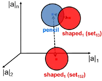
The set of excitations which minimize (15) will the one more easily leading itself to be reconfigured from the shaped to the pencil beam (see Fig. 2.5-2 ).
Fig. 2.5-2: Representation of the admissible solutions on space of all possible amplitude distributions
Once the minimum of (15) is determined, a local optimization technique can be used to perform the actual choice of the excitations common to both operative modes. One possible choice is to exploit an alternating projections procedure which acts here just as a final local optimizer.
To understand better the second and third step of the procedure an example is furnished.
Considering the only-phase reconfigurable fixed geometry arrays which radiates a pencil beam and a shaped beam. The shaped beam pattern, reported in Fig 2.5-3, is a cosecant power pattern.
Fig 2.5-3: Shaped beam radiated by a fixed geometry array
Applying the feasibility criterion first, the factorization and flipping of the zeros it is possible to define all the admissible excitation distributions in terms of amplitude and phase. For this specific example the complete set of complex distributions which permit to fit the assigned mask power pattern for the shaped beam are shown in Fig 2.5-4.
(a)
(b)
Fig 2.5-4: The complete set of admissible amplitude (a) and phase (b) distribution
Regarding the pencil beam a unique real solution is admissible to fit the power mask constraints. Fig. 2.5-5 shows the starting point for the optimal choice of the only-phase reconfigurable distribution. From the complete set of the complex distributions of the shaped beam case only the one which is nearest to the amplitude of the pencil beam is selected.
Fig. 2.5-5: Complete set of complex distribution which fit the shaped beam power mask and the unique real solution for the pencil beam pattern
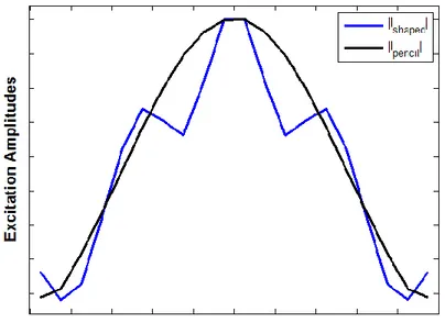
Fig. 2.5-6 reports the two nearest amplitude distributions for the two operative modes: blue line is for the shaped beam and dark line for the pencil beam.
Fig. 2.5-6: The nearest amplitude distribution for the shaped operative mode (blue line) and the pencil beam (dark line)
Acting a local optimization on the two selected amplitude distribution a final and unique amplitude distribution is used to find the excitations of the fixed geometry linear array.
Fig. 2.5-7: Final amplitude distribution for the two operative modes
After the definition of the amplitude distribution for the linear arrays the reconfigurability is obtained changing the phases in according to the operative mode desired by the operator. The two phase distributions are shown in Fig. 2.5-8 wherein blue there is the phase distribution for the shaped beam operative case while in red the phase for the pencil beam case (which is obliviously equal to zero).
Fig. 2.5-8: Final phase distribution for the two operative modes: blue the phase for the shaped beam and in red the phase for the pencil beam
This technique is a general approach and it can be used in order to create several cases of reconfigurable beams; an antenna which radiates pencil beams and shaped beam, an antenna which radiates two different shaped beams or antenna which radiates more than two patterns of general shape (more details in [50])
2.6 Planar arrays with fixed geometry synthesis radiating
reconfigurable beam
As demonstrated in the previous paragraph a deterministic and fast approach for the synthesis of a linear array with fixed geometry radiating a reconfigurable beam exists. The fundamental aspect of the synthesis procedure is the possibility that the shaped beam pattern can have a multiplicity of solutions in terms of complex coefficients to radiate the same desired power pattern.
In some particular cases this approach can be extended to the case of planar arrays, the circularly symmetric array, as demonstrated in [50]:
i. Planar arrays with symmetries which can be dealt with as one-dimensional polynomials
If the planar array does not exhibit one of these two conditions, then the factorization and the relative flipping of the zeros are not applicable and the proposed approach cannot be used.
The approach based on global optimization algorithm represents the solution for the general case of planar arrays with fixed geometry radiating a reconfigurable beam.
2.7 Isophoric sparse direct radiating array
In the first part of this chapter the deterministic synthesis for linear and planar arrays radiating pencil, shaped or reconfigurable beams when the geometry is fixed in advance is dealt with. As discussed in the first part of this thesis work, the deterministic power mask constrained synthesis of fixed-geometry arrays is the more simple case to manage because the far field has a linear relationship with the unknowns, the excitation coefficients of the array. After the case of fixed geometry the problem is to consider if it is possible to define a deterministic strategy for the synthesis of an isophoric sparse array. The isophoric sparse arrays are a particular class of arrays which is very appealing in the satellite communications.
Isophoric arrays mean that all the radiating elements of the arrays are fed with the same level of signal, see Fig. 2.7-1. This condition can introduce important advantages for an antenna which works in a hard environmental condition where the management of the resources, as the payload delivered power, is a critical aspect. In fact, in the isophoric arrays the same class of amplifiers is used and they work all at the same level of power and consequently there is an optimal DC to RF conversion. Moreover, the BFN which controls the array can be simplified because only simple equal amplitude T dividers are required.
Fig. 2.7-1: Representation of the isophoric sparse array
Another important advantage for this class of arrays is the sparsity in the geometry architecture of the radiant panel. Sparsity means that radiating elements are not uniformly distributed on the antenna aperture, regular lattice, but they are non-equally spaced creating an aperiodicity on the distribution, irregular lattice. The use of sparse arrays introduces some important consequences. At the first the number of radiating elements is smaller than the uniform equally-spaced arrays and therefore the number of active control points is reduced. This aspect entails a reduction of the manufacturing costs, of the mutual coupling inside the antenna aperture ( due to the increase of the inter-element distances) and a reduction of the antenna weight and mass. Another important advantage of the sparse arrays is the capability to avoid the appearance of grating lobes which are present in the uniform array with an inter-element distance greater than /2 (see Fig. 2.7-2).