2544 IEEE PHOTONICS TECHNOLOGY LETTERS, VOL. 18, NO. 23, DECEMBER 1, 2006
All-Optical Clock Recovery for NRZ-DPSK Signals
Giampiero Contestabile, Marco Presi, Nicola Calabretta, and Ernesto Ciaramella, Member, IEEE
Abstract—We experimentally demonstrate an optical clock recovery scheme for nonreturn-to-zero differential phase shifting keying (NRZ-DPSK) data. By using an optical circuit made by a proper fiber Bragg filter and a Fabry-Pérot based clock ex-traction circuit, we obtain a stable and low jitter 10-GHz optical clock signal. This signal shows comparable performance with the original electrical clock in bit-error-rate measurements and oscilloscope triggering operation.
Index Terms—All-optical clock recovery, Fabry-Pérot filter, optical communications, optical DPSK, semiconductor optical amplifier (SOA).
I. INTRODUCTION
T
HE synchronization issue is a serious challenge in several synchronous and asynchronous network architectures under study. In future high-speed transparent networks, a reli-able optical synchronization signal could be needed for several applications: namely, in receivers, in 3R regenerators and, in general, in all optical signal processing [1]. On the other hand, phase modulated signals, as differential phase shifted keying (DPSK) modulation formats, acquire increasing popularity because of a number of advantages in respect of the usual ON–OFF keyed (OOK) format. They show high resilience to nonlinear impairments [2] and, when using balanced detection, have around 3-dB optical signal-to-noise ratio (OSNR) advan-tage in respect of OOK. Regarding DPSK, while return-to-zero DPSK (RZ-DPSK) signals show strong clock components in both the optical and electrical spectrum, nonreturn-to-zero DPSK (NRZ-DPSK) signals have ideally no clock lines and, in practical realizations, only weak clock components. This makes by far more difficult the realization of clock recovery systems for NRZ-DPSK data. In principle, it could be possible to use established clock recovery schemes after DPSK demodulation and a following preprocessing stage used to emphasize the weak clock lines. Anyway, a simpler technique able to directly extract the clock would be preferred. Here, we experimentally demonstrate, for the first time to our knowledge, an optical circuit capable of NRZ-DPSK clock recovery. This circuit is mainly based on proper selective optical filtering and uses a semiconductor optical amplifier (SOA) for signal equalization. The clock-recovered signal shows high quality and stability to be potentially employed as an alternative to electronic circuits in a number of high-speed synchronization applications, i.e., optoelectronic continuous or burst receivers.Manuscript received June 14, 2006; revised October 10, 2006. This work was partially supported by the European Commission FP6 program (I.P. NOBEL II). The authors are with Scuola Superiore Sant’Anna, 56124 Pisa, Italy (e-mail: [email protected]).
Color versions of Figs. 1, 2, 4, and 5 are available online at http://ieeexplore. ieee.org.
Digital Object Identifier 10.1109/LPT.2006.887207
II. WORKINGPRINCIPLE
NRZ-DPSK data can be detected using narrow optical fil-tering [3]. By using this technique, a Gaussian-shaped filter with a full-width at half-maximum (FWHM) of around 60% of the bit rate provides demodulation of the incoming DPSK signal, while also strongly enhancing the signal tolerance to chromatic dispersion [3]. From a physical point of view, the same consec-utive symbols (data persistence), which are spectrally close to the carrier, pass through the filter unaffected. On the other hand, data transitions, which are aside in the spectrum, are cut. In [3], this filter was a fiber Bragg grating (FBG) used in reflection to-gether with an optical circulator. We highlight that the part of the input signal transmitted through the FBG is composed by all the transitions in the NRZ-DPSK sequence. Hence, it results in a pulse at every phase transition of the incoming data. Con-sequently, this sequence contains significant clock components. Using this RZ-like signal, clock recovery can be performed. To this aim, we use the circuit introduced in [4], [5], which is ba-sically made of a Fabry-Pérot filter (FPF) and an SOA. Thanks to the interplay of the memory properties of the high-finesse FPF with the free spectral range (FSR) matching the clock fre-quency and the power-limiting capability of the saturated SOA, it is possible to fill the zero slots of an incoming RZ data stream with optical pulses. Indeed, even in case of consecutive zero se-quences, when the FPF introduces pulses with decaying inten-sity (and thus amplitude oscillations arise), the saturation effects of the SOA can be used to equalize the pulses amplitude [4]. The effectiveness of this circuit in all-optical regenerative appli-cations was recently demonstrated in an over-million-kilometer transmission experiment with 3R regeneration for both RZ sig-nals [6], and NRZ sigsig-nals [7].
III. EXPERIMENT ANDDISCUSSION
The schematic of the clock extraction circuit is reported in Fig. 1. The optical carrier at nm is generated by a tunable laser. The NRZ-DPSK signal is obtained by means of a LiNbO phase modulator driven by a long PRBS sequence at 10.2 Gb/s. The signal is then amplified by an EDFA to 13 dBm to account for the circuit loss. Then it is sent via an optical circulator (OC) to the FBG.
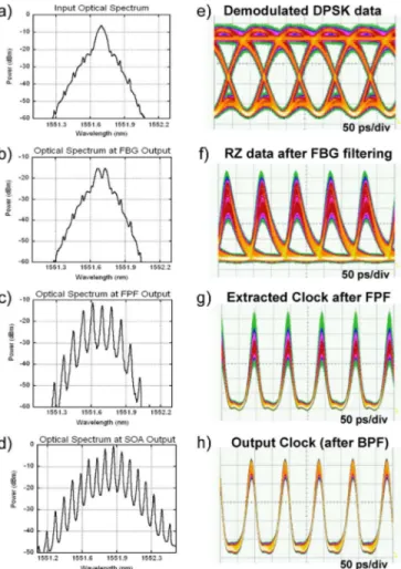
The FBG has a Gaussian reflectivity profile, with FWHM of 6 GHz and an almost flat phase response with low spurious dis-persion. Combined with the OC, the FBG provides in reflection effective DPSK demodulation [see Fig. 2(e)] [3]. The optical spectrum of the input DPSK signal and of the transmitted part from the FBG are reported in Fig. 2(a) and (b), respectively. The transmitted part of the signal is composed by a series of pulses, each one produced at a phase transition [Fig. 2(f)]. As can be
CONTESTABILE et al.: ALL-OPTICAL CLOCK RECOVERY FOR NRZ-DPSK SIGNALS 2545
Fig. 1. Experimental setup. TL: tunable laser, PM: phase modulator, EDFA: erbium-doped fiber amplifier, OC: optical circulator, FBG: fiber Bragg grating, PC: polarization controller, FPF: Fabry–Pérot filter, OI: optical isolator, SOA: semiconductor optical amplifier, and BPF: band-pass filter.
Fig. 2. a)–d) Evolution of the optical spectrum at various points in the clock recovery circuit. Resolution: 0.01 nm. d)–e) Eye diagram of the demodulated input DPSK signal and evolution of the optical clock in the extraction circuit.
seen in Fig. 3(a), the electrical spectrum of this signal has sig-nificant clock components.
This RZ-like signal is then sent to the FPF. The FPF is a fiber-based device with FSR GHz, Finesse FWHM
MHz . The insertion loss is around 4 dB when working with continuous-wave signals while it increases to around 8 dB when filtering the modulated signal of our experiment.
The filter wavelength can be tuned by means of a temperature controller and a polarization controller is used to maximize the filter output. The FPF selects the spectral clock lines, removing most of the incoming modulation [see Fig. 2(c)], producing a signal composed of 25-ps pulses. However, a significant amount of amplitude oscillations is still present [see Fig. 2(g)]. This is
Fig. 3. Electrical spectra at a) the input and b) the output of the clock extraction circuit.
related to the input pattern sequence and it is due to the limited memory effect of the FPF. It is a low-frequency noise that can be strongly reduced by exploiting the high-pass filtering prop-erty of the saturated SOA [4], [5]. To this aim, we use a polar-ization insensitive pigtailed SOA (Alcatel 1901A) with about 28 dB of small signal gain, around 200 ps of recovery time, and 6 dBm of output saturation power at 200-mA driving cur-rent. An optical isolator is used to reduce spurious reflections between the FPF and the SOA. The optical power at the SOA input was 2 dBm corresponding to around 20 dB gain com-pression. Finally, a 0.8-nm band-pass filter selects part of the optical spectrum at SOA output and removes the out-of-band ASE. The amplitude noise reduction effect can be clearly ob-served in the oscilloscope trace of Fig. 2(h), while the effect of the SOA on the optical spectrum is reported in Fig. 2(d). Here, we see some spectral red-shift due to pulse self phase modu-lation in the SOA. This effect combined with a slight detuning of the output BPF helps in amplitude noise reduction and ER improvement [8]. At the same time, in the electrical spectrum [reported in Fig. 3(b)] most of the modulation components pre-sented by the RZ-like signal of Fig. 3(a) are removed.
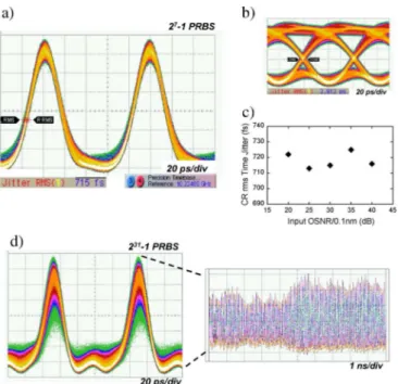
In the corresponding electrical spectrum, the carrier-to-mod-ulation ratio for the recovered clock increases to more than 50 dB. Finally, at the output of the clock extraction circuit, we obtain a sequence of 25-ps pulses at the input data rate. Their root-mean-square (rms) time jitter was measured by a sampling oscilloscope using the precision time-base reference module (having rms time jitter resolution 200 fs). It resulted in around 710 fs [Fig. 4(a)] for input OSNR ranging from 20 to 40 dB [Fig. 4(c)]. This value is reduced by more than four times in respect to the one of the input DPSK signal (about 2.9 ps) reported for comparison in Fig. 4(b). We note that in this last case this value includes a certain amount of inter-symbol
2546 IEEE PHOTONICS TECHNOLOGY LETTERS, VOL. 18, NO. 23, DECEMBER 1, 2006
Fig. 4. a) Time jitter measurement on the recovered clock. b) Time jitter measurement on the data. c) Recovered clock time jitter versus input OSNR. d) Persistence trace and detail of the output clock sequence in case of2 0 1 sequence.
jitter due to the demodulation process that cannot be exactly evaluated. Nevertheless, input-output jitter reduction can be expected by previous results [9].
The present results, obtained for a long PRBS, were limited by the Finesse of the available FPF. Indeed, when using longer sequences, as shown in Fig. 4(d), residual pattern-related amplitude oscillation leads to a degradation of the clock recov-ered signal. For such sequences, a filter with higher finesse is required. From our previous work [5], we infer that a filter with a finesse of around 250 can guarantee efficient operation up to a long sequence.
Finally, the good quality and stability of this clock is con-firmed by two additional measurements. We first triggered with the recovered clock a sampling oscilloscope to measure the eye diagram. After 1-h accumulation time, we find the eye diagram still completely fixed and open (see inset of Fig. 5). Supporting this observation, Fig. 5 reports a comparison of the bit-error-rate (BER) curves obtained using as clock signals, the elec-trical clock from the pattern generator, an elecelec-trical clock recov-ered with an electrical clock recovery unit, and the optical clock recovered signal by our scheme, respectively. No appreciable power penalty can be observed using the various synchroniza-tion signals.
IV. CONCLUSION
We demonstrated clock recovery from NRZ-DPSK data for the first time. For a 10-Gb/s signal, we obtained a 10-GHz clock
Fig. 5. BER comparison using different clock signals. In the inset, demodu-lated DPSK eye diagram with 1-h persistence time obtained when triggered by the optical clock.
of 25-ps pulses having 710-fs rms time jitter. The recovered clock signal has comparable performance with the original elec-trical synchronization signal in both oscilloscope triggering and BER measurements. Due to its working principle, the present technique can be extended to higher bit rates by scaling by the same factor the FBG-FWHM and the FPF-FSR. When in-creasing the bit rate, wavelength stability requirements of the scheme are relaxed.
REFERENCES
[1] S. Bigo, O. Leclerc, and E. Desurvire, “All-optical fiber signal pro-cessing and regeneration for soliton communications,” IEEE J. Sel.
Topics Quantum Electron., vol. 3, no. 5, pp. 1208–1223, Oct. 1997.
[2] A. H. Gnauck and P. J. Winzer, “Optical phase-shift-keyed transmis-sion,” J. Lightw. Technol., vol. 23, no. 1, pp. 115–130, Jan. 2005. [3] A. D’Errico, R. Proietti, L. Giorgi, G. Contestabile, and E. Ciaramella,
“WDM-DPSK detection by means of frequency-periodic Gaussian fil-tering,” Electron. Lett., vol. 42, no. 2, pp. 112–113, Jan. 19, 2006. [4] G. Contestabile, A. D’Errico, M. Presi, and E. Ciaramella, “40-GHz
all-optical clock extraction using a semiconductor-assisted Fabry-Pérot filter,” IEEE Photon. Technol. Lett., vol. 16, no. 11, pp. 2523–2525, Nov. 2004.
[5] G. Contestabile, M. Presi, N. Calabretta, and E. Ciaramella, “All-op-tical clock recovery from 40 Gbit/s NRZ signal based on clock line enhancement and sharp periodic filtering,” Electron. Lett., vol. 40, no. 21, pp. 1361–1362, Oct. 14, 2004.
[6] Z. Zhu, M. Funabashi, Z. Pan, L. Paraschis, and S. J. B. Yoo, “10 000-hop cascaded in-line all-optical 3R regeneration to achieve 1 250 000-km 10-Gb/s transmission,” IEEE Photon. Technol. Lett., vol. 18, no. 5, pp. 718–720, Mar. 1, 2006.
[7] M. Funabashi, Z. Zhu, Z. Pan, L. Paraschis, and S. J. B. Yoo, “Optical clock recovery and 3R regeneration for 10-Gb/s NRZ signal to achieve 10 000-hop cascadability and 1 000 000-km transmission,” IEEE
Photon. Technol. Lett., vol. 18, no. 20, pp. 2078–2080, Oct. 15, 2006.
[8] M. L. Nielsen, B.-E. Olsson, and D. J. Blumenthal, “Pulse extinction ratio improvement using SPM in an SOA for OTDM systems applica-tions,” IEEE Photon. Technol. Lett., vol. 14, no. 2, pp. 245–227, Feb. 2002.
[9] V. Roncin, S. Lobo, L. Bramerie, and J. C. Simon, “Phase noise re-duction in all optical clock recovery at 43 Gb/s for 3R regeneration applications,” in Proc. ECOC 2006, Cannes, France, We3.P.91.