Deformable Registration using Patch-Wise Shape Matching
Francesco Bonarrigoa, Alberto Signoronia, Mario Botschb
aInformation Engineering Department, University of Brescia, Italy bComputer Graphics & Geometry Processing Group, University of Bielefeld, Germany
Abstract
We present a novel approach for non-rigid registration of partially overlapping surfaces acquired from a deforming object. To allow for large and general deformations our method employs a nonlinear physics-inspired deformation model, which has been designed with a particular focus on robustness and performance. We discretize the surface into a set of overlapping patches, for each of which an optimal rigid motion is found and interpolated faithfully using dual quaternion blending. Using this discretization we can formulate the two components of our objective function— a fitting and a regularization term—as a combined global shape matching problem, which can be solved through a very robust numerical approach. Interleaving the optimization with successive patch refinement results in an efficient hierarchical coarse-to-fine optimization. Compared to other approaches our as-rigid-as-possible deformation model is faster, causes less distortion, and gives more accurate fitting results.
Keywords: Non-rigid registration, nonlinear shape deformation 1. Introduction
The need to compensate for deformation present on a set of captured data, or between modeled objects, is inbred to all dynamic 3D imaging and graphics ap-plications, such as capturing, modeling, representation, recognition, morphing, and animation. In particular the 3D scanning of physical objects that undergo some kind of non-rigid motion leads to a space-time shape match-ing problem, which has to be solved to achieve a non-rigid alignment between partial views.
Depending on the application and the scanning sys-tem, the type of non-rigid motion the object is under-going and the distortion caused for local and global features can vary a lot. This mainly depends on the temporal distribution of the single scans. For real-time scanners the deformation of consecutive scans is rather small and their overlap rather large. The acquired data is typically not problematic from a registration perspec-tive. In contrast, when high-end scanners are used to ac-quire precise high-resolution scans for production qual-ity models, the delay between two consecutive scans is significantly larger, leading to more deformation and less overlap between individual scans, and therefore to a more challenging registration problem.
Large-scale deformations require a more sophisti-cated regularization of the deformation field in order to
prevent implausible deformations and to keep the sur-face locally rigid during the registration process (Fig-ure 1). Since the small strain assumption does not hold for large deformation, the regularization is typically implemented as some nonlinear physics-inspired strain measure, which is to be minimized simultaneously with the fitting error between the two scans. The resulting nonlinear minimization is challenging in terms of nu-merical robustness and computational performance.
In this paper we present an approach for accurate and robust deformable registration of models acquired by high-quality, high-resolution 3D scanners. Our method is able to compensate for various kinds of motion and deformation the acquired data can exhibit, which is achieved by a nonlinear, physics-inspired deformation regularization. Our method is based on a space de-formation approach, such that it can process arbitrary point-sampled data and is not a↵ected negatively by de-generate input meshes. We discretize the surface into a hierarchy of partially overlapping patches, for each of which a distinct rigid transformation is found by min-imizing a global objective function that takes into ac-count both the need for accurate alignment as well as for the regularity of the deformation field. The result-ing rigid transformations are then extended to all sample points in a rigid manner using dual quaternion interpola-tion. As a result of this as-rigid-as-possible deformation
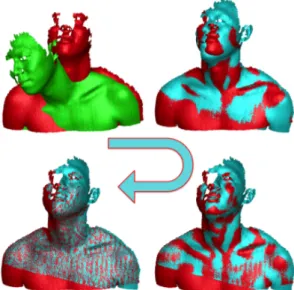
Figure 1: Non-rigid registration of the Torso dataset, where the green scan is to be registered to the red target model. The cyan models show the the deforming surface during the optimization process, until convergence is reached.
our dynamic registration avoids unnecessary distortion and faithfully preserves geometric features. Both the fitting and regularization terms are based on a global shape matching strategy, which results in a unified ob-jective function that can be minimized in a numerically very robust manner. Finally, our hierarchical patch dis-cretization and correspondence refinement further im-proves stability and accelerates convergence. An exam-ple of our deformable registration is shown in Figure 1. Our approach demonstrates a favorable combination of fitting accuracy, geometric feature preservation, and computational performance, as we evaluate on several challenging datasets and compare to recent state-of-the-art techniques. As such, our approach can have many practical applications for the acquisition of objects that undergo undesired motion, such as acquisition of body parts for orthopedic applications, as well as for the anal-ysis of deformation with respect to a reference surface for manufacturing quality control.
2. Related Work
Non-rigid shape registration belongs to the wide fam-ily of shape correspondence problems [1, 2, 3], and its understanding is of fundamental importance for a vari-ety of advanced applications in computer graphics, geo-metric modeling, and computer vision. In this work we concentrate on non-rigid registration of partial views, which is a fundamental problem in 3D scanning. Since
all acquisition sensors can only provide a limited field of view, scanning a deforming object requires the solu-tion of partial shape matching problems. This defines what has been called the problem of time-varying (non-rigid) registration, which has found di↵erent solutions according to the attainable acquisition frame rate for a given scanning technology (real-time scanning or non-interactive scanning). This technological distinction can also act as a classification of non-rigid registration tech-niques, since the amount of deformation that needs to be taken care of is typically less for scanners with a faster acquisition rate.
Small Deformations
A first family of approaches can be associated to the advancements of real-time scanning technologies [4, 5], where data acquisition is characterized by a regular and dense frame rate (in the order of dozens of frames per second). Recently developed, handy, and a↵ordable de-vices from the entertainment industry are having a great impact on research in computer vision, computer graph-ics, and multimedia [6], allowing for 3D object model-ing and scene reconstruction [7]. With respect to profes-sional high-end scanners, real-time devices provide only limited spatial resolution and a high amount of geomet-ric noise. For objects that do not move or deform too quickly, subsequent view overlapping is quite high and the deformation between scans is rather small, therefore allowing to assume that subsequent scans are already coarsely aligned.
This inspired the development of non-rigid variants of rigid alignment methods relying on the estimation of correspondence sets [8]. An alternative method that does not have to explicitly compute correspondences has been proposed in [9]. Under the gradual deforma-tion hypothesis, template-free methods that guarantee global consistency of the space-time object reconstruc-tion and prevent erroneous topology changes have been proposed in [10, 11], while the template-based approach [12] has been proposed in the same perspective. Other approaches consider non-rigid alignment as a form of compensation for nonlinearities related to the acquisi-tion device, such as optical distoracquisi-tion and calibraacquisi-tion er-rors [13, 14]. A multiview global alignment solution of these issues has been proposed in [15], while loop clo-sure issues have been addressed in [16].
Large Deformations
A second group of approaches, which is more simi-lar to the problem we wish to address, aims to obtain a high-quality, precise model of a deforming object, for
instance for the sake of reverse engineering or high-fidelity reproduction. The acquisition is usually done at irregular time intervals, therefore a high overlap of con-secutive views cannot be assumed, nor can concon-secutive scans be considered coarsely aligned as in the case of real-time scanners. It is worth noting that the presence of deformation could be considered either as a kind of noise to compensate for, or, on the contrary, as useful additional information that can be attached to a static “consensus model” of the object being acquired.
In order to constrain the registration problem some approaches assume the availability of prior knowledge of either the object shape (such as template-based ap-proaches [17, 18, 19]) or of the deformation model (e.g., assuming articulated motion [20, 21]). Under general deformation assumptions, some approaches based on non-rigid ICP have been proposed [22, 18]. In par-ticular, a reference template is needed in [22], while [18] presents a reliable correspondence selection strat-egy based on a combination of to-point and point-to-plane metrics. The method proposed in [23] esti-mates a di↵eomorphism between data that have under-gone large deformations.
Other approaches successfully handle large and gen-eral deformations without the need of a-priori assump-tions by minimizing a global energy that takes into ac-count both fitting error and deformation smoothness [24, 25, 12]. Our method is most closely related to these latter approaches, as we also employ an objective function consisting of fitting and regularization terms. However, our method di↵ers in a few important as-pects, which result in a noticeable improvement over the very successful and quite mature state-of-the-art tech-niques. We discuss the similarities and di↵erences in Section 5.3, after having presented our method in detail in the following sections.
In general, when the deformation increases, the prob-lem of automatically searching for reliable correspon-dences between partial views becomes more challeng-ing. Several interesting alternatives to closest-point cor-respondences have been proposed, based on geometric features and geodesic distances [25], on the Heat Ker-nel Map [26], M¨obius transformation [27], or a blending of several intrinsic maps [28]. The focus of this paper is the deformation model instead of the computation of robust correspondences. We therefore restrict to simple closest-point correspondences and use a stronger regu-larization to prevent distortions due to wrong correspon-dences at the early stage of the registration. Even larger deformations of the input scans could be handled by en-hancing our method by any of the above-mentioned cor-respondence computations.
3. Method Overview
Our main objective is to estimate the optimal defor-mation capable of aligning a scan S (the surface we want to deform) to a target model M (the reference sur-face), while at the same time preserving the shape of the scan as much as possible.
Solving this problem for all the points simultaneously can quickly become an impractical task, depending on the size of S. However, since the deformation of the ob-ject typically is a smooth function, we can safely assume that nearby points undergo similar deformations, and discretize the problem at a coarser resolution, solving the registration for a subset of evenly-spaced points, and then interpolating the deformation to the rest of the scan. Similarly to [29] we denote these points as nodes, and refer to their set with N. Each node has a radius of influ-ence, chosen such that the nodes’ influence regions cor-respond to a set of partially overlapping patches. Each node n 2 N is then associated a rigid transformation, i.e., a rotationRn 2 IR3⇥3 and a translation tn 2 IR3. Since rotations can be represented by 3 parameters, this yields 6 degrees of freedom (DoFs) per node. During the optimization the density of the set N will be hier-archically adapted in a coarse-to-fine manner, so that distortion on S is progressively compensated.
The per-node rigid motions are determined by mini-mizing an objective function consisting of a fitting term Efit, which drives the deformation of the scan toward the model, and a regularization term Ereg, which maintains a smooth and physically plausible deformation through-out the optimization.
For thefitting term we resort to a set of correspon-dences C = {P, Q}, where the sample points p 2 P ⇢ S are selected from the scan S, while their correspond-ing pointsq 2 Q ⇢ M are found on the target model M. The fitting term penalizes for each node n 2 N the (squared) distance of corresponding points (p, q) 2 Cn that are within n’s influence radius, where q is being transformed by n’s rotation and translation:
Efit = X n2N X (p,q)2Cn kRnp + tn qk2 |N| · |Cn| . (1) The rigid transformations of neighboring nodes n and m are not completely independent, but will instead be sim-ilar due to correspondence points (p, q) located in the partial overlap of their influence regions, i.e., Cn\ Cm. Nevertheless, theregularization term explicitly penal-izes the di↵erence between neighboring nodes’ transfor-mations, as measured by the distance of pointsp in their
Setup phase
Update phase Minimization phase
select iteration parameters
select nodes &
samples compute weights deform surface finished?
update
correspon-dences
classify nodes optimize node
transformations converged? converged?
Y
N N
N
Y Y
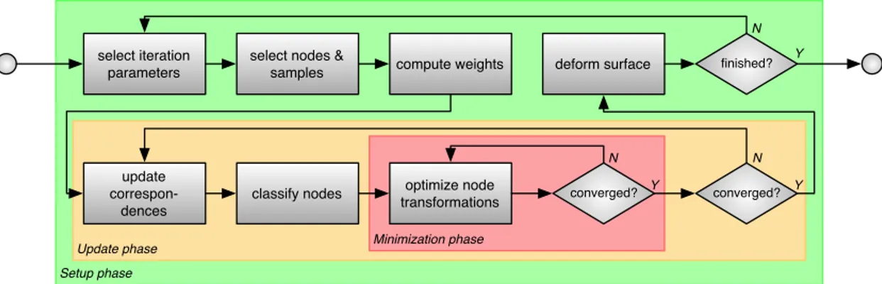
Figure 2: The proposed deformable alignment pipeline, split into three nested phases: Setup, Update and Minimization.
overlap region Pn\ Pmafter being transformed by the rigid motions of n and m, respectively:
Ereg = X n2N X m2N X p2Pn\Pm kRnp + tn Rmp tmk2 |N|2· |Pn\ Pm| . (2) The global energy is a weighted sum of fitting and reg-ularization
Etotal = wfitEfit + (1 wfit) Ereg, (3) where the fitting weight wfitis increased during the op-timization so that the surface is deformed in a sti↵-to-smooth manner.
Our framework can be considered as a sequence of operations distributed on three nested loops (see Fig-ure 2), where in each loop some of the optimization features or parameters are selected and considered fixed throughout the execution of the inner loops. The three phases are outlined below, and the involved techniques are described in detail in the following section.
Thesetup phase is responsible for adjusting the opti-mization parameters (Section 4.1) and for selecting the set of nodes N and correspondence samples P (Sec-tion 4.2). At this step we also compute the weights used for interpolating the nodes’ transformations to all the points of the scan S (Section 4.3). The setup phase is repeated until a given number of iterations is reached.
Theupdate phase updates the target points P for cor-respondences C = (P, Q) according to the current de-formation estimate of S (Section 4.4). It also performs a classification of the nodes (Section 4.5) based on the updated correspondences, which allows to speed up the minimization and avoid potential instabilities. The up-date phase is terminated when the correspondences C do not improve any further.
In theminimization phase the energy (3) is solved while keeping the set of parameters, nodes, and corre-spondences fixed (Section 4.6). Similarly in spirit to
[30], we can interpret all the nodes as rigid objects, which are coupled to the model M through (1) and to each other through (2). In this view, the minimization of (3) is a global shape matching problem, which can be solved robustly as shown in [31, 32].
4. Detailed Description and Implementation Notes 4.1. Parameter selection
The proposed approach relies on three main param-eters. Besides the first one, the other two require an initial and final value each, so that at a given iteration the current values for these parameters are linearly in-terpolated.
The first parameter is the number of iterations for which the setup phase, i.e., the outer loop, should be re-peated. This value may require tuning according to the complexity of the deformation that has to be handled: more demanding cases may need a greater number of iterations, so that the scan slowly adapts to the target model.
Thenode spacing represents the minimum Euclidean distance between two nodes (and indirectly defines the spacing of correspondence samples, Section 4.2). While its initial value should be tuned according to the met-ric size of the processed scan, its final value controls the smallest deformation that can be handled. During the optimization this value decreases, so that the num-ber of nodes increases. This way the optimization ini-tially takes care of large, low-frequency deformations, while handling small, high-frequency ones at the end, in a coarse-to-fine manner.
The fitting weight wfit represents the weight associ-ated to the fitting term Efitin the objective function (3). Similar to other approaches, this parameter is monoton-ically increased during the optimization (typmonoton-ically from
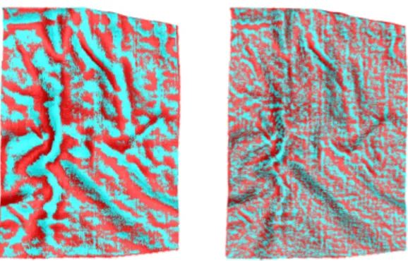
Figure 3: Alignment between scan S (cyan) and target model M (red) obtained with same number of nodes N, but di↵erent numbers of cor-respondence samples P. Left: samplespacing = nodespacing. Right: sample spacing = node spacing/4.
0.1 to 0.9), causing the surface to remain sti↵ during the initial optimization stages, while getting softer toward the end, in a sti↵-to-smooth fashion.
4.2. Node and sample points selection
At every iteration of the setup phase we select a pro-gressively denser set N of regularly-spaced nodes on the scan S, controlled by the node spacing parameter, which can be implemented efficiently through simple farthest point sampling. The node spacing also controls the sampling of the correspondence points P. A key dif-ference of our method to other approaches, such as [25] and [12], is that we chose the density of correspondence samples as a multiple of the node density, which leads to a more accurate estimation of the deformation field (see Figure 3). In particular, in all our examples we chose the spacing of correspondence samples to be 1/4 of the node spacing. An example of how the sets N and P are distributed on the scan S is shown in Figure 4.
4.3. Blending of rigid transformations
The deformation of pointsp 2 S is computed by terpolating the nodes’ rigid transformations. The in-terpolation weights can be computed by an arbitrary smooth weighting function with local support radius r. In our case a simple inverse distance weighting turned out to be sufficient, where the weight wn(p) of point p with respect to node n is computed as
wn(p) = 1 kn pk r
! +
.
Here, r is the influence radius of node n, typically cho-sen as 1.25 times the node spacing, and (·)+clamps neg-ative values to zero. The weights are normalized such that Pn2Nwn(p) = 1.
Once the blending weights have been computed, we can interpolate the transformations of the nodes to all other points of the scan. The approaches of Huang et al. [25] and Li et al. [24, 12] employ linear blend skin-ning [33] for this task, which is known to produce ar-tifacts when interpolating strongly di↵erent transforma-tions. In contrast, we employ dual quaternion skinning [34], which produces a more accurate, artifact-free in-terpolation of rigid transformations by inherently pre-serving the orthogonality of rotation matrices. Due to the more complex formulation of the dual-quaternion interpolation, we cannot integrate the interpolation of node transformations into the minimization of corre-spondence errors, as has been done in the embedded deformation approach [24, 12] (for simple linear inter-polation of node transformations). Instead, our dual-quaternion interpolation is performed after node trans-formations have been computed, similar to [25]. 4.4. Correspondence update
Every time new correspondence samples P ⇢ S have been selected (Section 4.2) or have been deformed dur-ing the registration process (Section 4.3), we have to update their corresponding points Q on the target model M.
To this end, we find for each samplep 2 P its clos-est pointq 2 M. To avoid erroneous correspondences, we discard any point couple (p, q) if their Euclidean dis-tance or the angle between their normals is above a cer-tain threshold [35]. These thresholds are linearly inter-polated from rather large initial values to more stringent final values, such that towards the end of the optimiza-tion, when the surfaces are very close to each other, outliers can be e↵ectively rejected. While the thresh-olds on the distance of corresponding points depends on the model dimensions and the amount of noise and de-formation present, the normal deviation thresholds are 60 in the beginning and 30 at the end for all our ex-amples. The updated correspondence set then becomes C = (P, Q).
4.5. Nodes classification
To guarantee a numerically robust computation of each node’s rigid transformation by minimizing the ob-jective function (3), each node has to be properly con-strained. This can happen either through sufficient valid constraints for the fitting term (1), or through a suffi-cient overlap with neighboring (constrained) nodes in the regularization term (2).
Nodes that do not have a sufficient number of valid correspondences are excluded from the fitting term. If
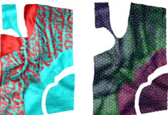
Figure 4: An extreme (synthetic) version of the Pillow dataset. Left: The scan (cyan) and the target model (red) after alignment. Right: Classification of nodes N (yellow, cyan, pink) and correspondence samples P (green, red) on the scan S. Valid correspondence samples are green, invalid ones are red. Yellow nodes have sufficiently many valid correspondences, cyan nodes are not (sufficiently) connected, and pink nodes do not have sufficient correspondences, but are suf-ficiently connected to a constrained region. Both the ill-connected nodes (upper-left) and isolated nodes (lower-right) are correctly la-beled as disconnected.
such nodes still have a sufficient overlap with other nodes, they can be used in the regularization term. Oth-erwise, they have to be completely discarded from the optimization. Since in our approach the densities of nodes N and correspondence samples P are coupled (Section 4.2), we can simply use the fixed thresholds |Cn| > 20 and |Pn\ Pm| > 20 for these tests.
The node classification starts by collecting all nodes with sufficient correspondences (yellow in Figure 4). From each of those a breadth first search is started, pro-ceeding to all neighboring nodes with sufficient over-lap. At the end of the process, all unmarked nodes are considered disconnected and are temporarily excluded from the current optimization step (cyan in Figure 4). We found this node classification to be crucial for avoid-ing numerical instabilities, in particular when workavoid-ing with raw scans that did not undergo any sort of prepro-cessing and therefore might contain outliers as well as ill-constrained (or un-constrained) regions.
4.6. Numerical optimization
In the numerical minimization of (3), we can consider each node as an individual rigid object (having 6 DoF for rotation and translation). These rigid parts are cou-pled to each other through the regularization term (2), which is closely related to the PriMo approach [32, 30], where it has proven to be a physically plausible de-formation model. In contrast to the interactive PriMo application, in our approach the deformation is driven by the correspondences, i.e., by the fitting term (1) that
couples the nodes of the scan to the target model. Our optimization can be solved robustly and efficiently by the Gauss-Newton approach described in [31, 32]. In each Gauss-Newton iteration, rigid transformation up-dates are linearized as affine transformations (helical screw motions), and the optimal updates are found by solving a sparse 6 |N| ⇥ 6 |N| linear system. The re-sulting screw motions are projected back to the rigid motion manifold and used to update the current node transformations. This kind of nonlinear optimization was shown to be very robust and reasonably efficient in [32, 30], and worked reliably in our application. 5. Results and discussion
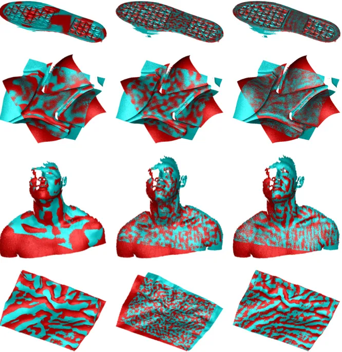
The described approach has been implemented in C++ and tested on a 2.4 GHz Intel Dual Core lap-top with 4 GB of RAM. The code can exploit multi-core processing. Several datasets were considered, each composed by a pair of surfaces, previously referred to as the scan S and the target model M, where the former presents both some degree of overlap and deformation with respect to the latter. The Sole (a shoe sole subject to elastic bending), Mould (a foam rubber mould sub-ject to external deforming forces), and Pillow datasets (a pillow taken in two di↵erent creased states) were ac-quired with a high-resolution, structured-light profes-sional scanner, while the Torso dataset (kindly provided by the authors of [24]) was obtained through the fast scanner described in [5]. Both the Sole and Mould datasets are characterized by a smooth, low-frequency warping, however the Sole is a problematic dataset for any ICP-based technique (such as ours) due to the pres-ence of repeated patterns, which causes many local min-ima in the objective function and increases the risk of obtaining a suboptimal alignment. In addition we tested our approach on some face scans, which represent more noisy and partial surfaces with complex deformations. 5.1. Alignment performance
For all the considered datasets, our approach suc-ceeded in estimating a physically plausible deformation, as testified by the alignment shown in Table 1 and Fig-ure 5. The final average distance between the scans is consistent among all datasets with the exception of the Torso model, where a greater final distance is justified by the more noisy surface compared to the other high-resolution scans. Thanks to our physically plausible regularization term in the error functional, the extension of the deformation field to the rest of the surface leads to a plausible warping, even for areas where no overlap with the target surface exists.
This is shown for the Sole dataset, where the wedge heel is correctly bent according to the rest of the data, as well as for the Torso dataset, where the upper part of the face has been warped correctly, even though it was completely missing on the target model.
More examples with noisy surfaces, incomplete data, and partial overlap are shown Figure 6, where a scan of a neutral face is registered to scans of di↵erent fa-cial expressions. As the corresponding statistics in Ta-ble 2 demonstrate, our method succeeds to accurately register the di↵erent scans in reasonable time. For the example “neutral!smile” a higher resolution could be used to reduce the deviation in the mouth area, however, the other regions are sufficiently accurate. Hence, this problem could well be solved using adaptive (instead of uniform) refinement, which we leave for future work. Nevertheless, these examples demonstrate the capabil-ity of our method for building a blend shape facial rig by matching a neutral scan (or a template facial model) to recorded facial expressions.
5.2. Timing breakdown
We now present a breakdown of the involved compu-tations of our approach with respect to the conceptual operations described in the pipeline presented in Fig-ure 2. While the exact time balance may vary depending on the dataset characteristics and node density, the fol-lowing general trend can be observed. The most time-consuming part involves the solution of the minimiza-tion problem, which accounts for 40% of the total time, followed by the correspondence update phase, which re-quires 25% of the total time. Next is the application of the deformation field to the entire surface (15%), while the remaining 20% of the time is distributed among the other operations (parameter selection, selection of nodes and samples, weight computation, node classifi-cation, I/O operations).
5.3. Comparison to other techniques
In order to further assess our approach, we compare to the two approaches most similar to ours, namely the ones of Huang et al. [25] and Li et al. [12] (which im-proves upon [24]). Since our approach shares certain details with [25] and [12], but di↵ers in other crucial aspects, we start with a theoretical discussion of the similarities and di↵erences between the methods, before providing an experimental comparison.
Methodological comparison. The approach of Huang et al. [25] selects uniformly distributed nodes on the de-forming scan, and infers their deformation from a set
of robust correspondences computed by taking into ac-count both geodesic distance and feature signature con-sistency. During the optimization, neighboring nodes undergoing the same rigid transformation are clustered and are assigned a common transformation. However, since these clusters are only allowed to grow, the fi-nal phase of the optimization may be hampered since sub-cluster alignment accuracy would be required to im-prove the fitting quality. Their error functional consists of a fitting and a regularization term, both weighted with constant factors.
Similarly to [25] we compute a hierarchy of nodes, but instead of a fine-to-coarse node clustering, our node selection strategy actually is a coarse-to-fine optimiza-tion. This is particularly useful toward the end of the processing, when optimization of the deformation field at node level is necessary to reach complete conver-gence. Moreover, our adaptive balancing between fit-ting and regularization is more flexible and further con-tributes to reaching more accurate results.
The method of Li et al. [12] (which improves upon [24]) also employs an adaptive weighting for fitting and regularization in order to reach a higher fitting accu-racy. Their regularization is based on the embedded deformation approach [29], which also discretizes the scan by a set of nodes that build the so-called deforma-tion graph. Each node has an associated affine trans-formation, which is kept close to a rigid motion by a special term in their energy formulation. As a conse-quence, their method uses 12 DoFs per node (affine tion), whereas we use 6 DoFs per node only (rigid mo-tion). This consequently reduces memory consumption and computational costs for our numerical optimization. In [12] the resulting node transformations are then lin-early interpolated to all points of the scan, which for highly di↵ering matrices might lead to the well-known artifacts of linear blend skinning (as described in [34]). In contrast, our use of dual quaternion skinning should help to avoid these artifacts and reduce distortion during the registration process.
In contrast to [25], however, Li et al. perform an adap-tive refinement of the deformation graph in region of highly di↵ering local transformation, which somewhat reduces the linear interpolation problems and allows for more localized updates of the deformation field. In com-parison, our hierarchical but uniform discretization is less flexible, and an adaptive refinement is a promising subject of future work.
Our method di↵ers from both approaches by select-ing a greater number of correspondences compared to the node density, which leads to superior alignment ac-curacy, as demonstrated in Section 4.2 and Figure 3.
Model |S| |N| initial dist. [mm] final dist. [mm] iters time [s]
Sole 360 k 1986 20 0.035 10 77
Mould 1200 k 1095 100 0.034 4 37
Torso 135 k 953 600 0.142 50 58
Pillow 200 k 2423 5 0.031 10 55
Table 1: Registration performance for the models of Figure 5. |S| is the complexity of the scan, |N| the maximum number of nodes reached during optimization. Reported distances correspond to the average distances in the initial and final state, respectively. The iterations numbers correspond to the outer-most loop (setup-phase).
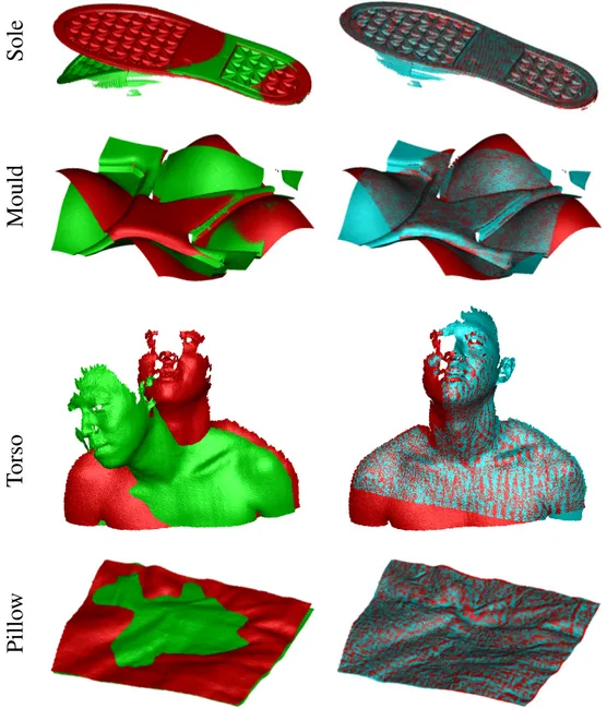
Sole
Mould
Torso
Pillo
w
Figure 5: Registration results. The left column shows the original scan (green) and the target model (red). The right column show the deformed scan (cyan) and the target model (red).
Model |S| |N| distance [mm] time [s]
Neutral ! Happy 114k 2257 0.066 137
Neutral ! Smile 114k 2207 0.092 123
Neutral ! Sad 114k 2191 0.072 131
Neutral ! Asym. 114k 2220 0.072 109
Table 2: Registration performance of the face scans of Figure 6. |S| is the complexity of the scan, |N| the maximum number of nodes reached during optimization. Reported distance corresponds to the average distances in the final state.
neutral
happ
y
neutral
smile
neutral
sad
neutral
asymmetric
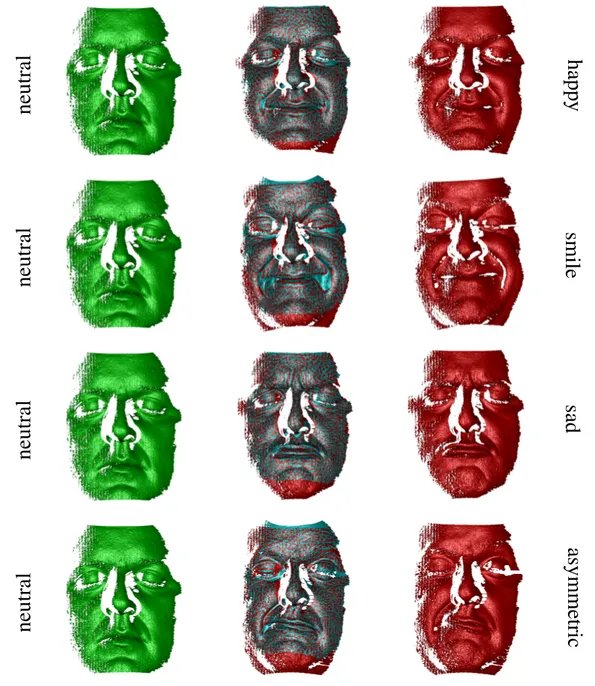
Figure 6: Registration of face scans. The left column shows the neutral source mesh, the right column the target expressions, and the center the overlay of deformed neutral scan (cyan) and target (red).
Model Approach Distance [mm] Distortion [·105] |N| Time [s]
Sole Huang et al. 08Li et al. 09 0.2480.041 9.342.53 400730 604
Proposed (D) 0.040 2.48 725 35
Mould Huang et al. 08Li et al. 09 0.0940.045 2.520.47 400709 542
Proposed (D) 0.036 0.29 710 27
Torso Huang et al. 08Li et al. 09 0.6980.178 29.68.72 400268 384
Proposed (D) 0.194 8.46 266 35
Pillow Huang et al. 08Li et al. 09 (*) (0.049)0.240 29.22.68 400419 623
Proposed (D) 0.086 2.36 421 13
Table 3: Comparison between Huang et al. [25], tested on a single-core 3.2 GHz CPU, Li et al. [12], tested on a 2.6 GHz Intel Core i7, and our approach (downgraded for comparison, D), tested on a 2.4 GHz Intel Dual Core. (*) Note that the method of Li et al. failed for the Pillow example (shifted alignment, see Figure 7).
Experimental comparison. The authors of both ap-proaches kindly agreed to apply their techniques to our datasets, and provided us with the deformation results as well as with the maximum number of nodes em-ployed and the computational performance. In order to provide a fair experimental comparison we decided to adapt (downgrade) our algorithm to the approach that obtained the best results between the two. In particu-lar, we decreased the maximum number of nodes em-ployed by our algorithm to roughly match the number of nodes of the best algorithm. In addition, since both other methods do not exploit multi-core processing, we deactivated this feature in our algorithm. In the fol-lowing, we indicate this adapted configuration with the symbol (D) to distinguish its results from the ones ob-tained by employing our optimal working configuration, already presented in Table 1 and Figure 5. The results of the comparative assessment are organized in Table 3 and Figure 7.
Non-rigid registration is always a compromise be-tween fitting accuracy and geometric distortion. Zero fitting error can be achieved by simply projecting the scan onto the target model, but this would cause high distortion. Performing only a rigid registration avoids any distortion, but leads to a high fitting error. To allow for a more meaningful comparison we therefore also re-port the isometric distortion in Table 3. We measure distortion (in a simplified manner) as the squared rela-tive di↵erence of edge length between the original scan (length Le) and the deformed scan (length le), averaged over all edges e 2 E of the scan:
1 |E| v tX e2E (le Le)2 L2 e
This measure does (intentionally) not penalize bend-ing, but is sensitive to stretching and shearing. Obvi-ously a certain amount of distortion is required to match the scan to the target model. However, for two meth-ods reaching a similar fitting accuracy, the one causing fewer distortion should be the preferred solution.
From a visual inspection of the results (Figure 7), as well as the alignment error and geometric distortion reported in Table 3, we conclude that the approach of Huang et al. [25] yields the least accurate results for the given datasets. These results seem to confirm the con-siderations with regard to the fine-to-coarse node clus-tering: Although it can grant satisfying results for ob-jects undergoing homogeneous, smooth deformations, it can be a limiting factor when the deformation be-comes more heterogeneous, or when small portions of data need to be accurately registered. While its com-putational performance greatly outperforms the other approaches, the alignment performance proved to be unsatisfactory for the given datasets, regardless of the number of nodes employed (as testified by the Torso and Pillow datasets, for which said technique employs a greater and a comparable number of nodes as the other approaches).
We compared our approach (D) to the results ob-tained by Li et al. [12], employing a similar number of nodes as the ones declared by their technique. While for the Sole and Mould datasets our approach seem-ingly reaches better visual results, in the Torso case Li’s method achieves a better deformation. For the Pillow dataset Li’s method fails to reach any plausible result, while our approach achieves a meaningful alignment. In general, our alignment distances are similar to those of Li et al., with the exception of the Pillow dataset, which
Figure 7: Comparison to other approaches by means of visual inspection of the deformed data (cyan) and the target model (red) (same datasets as in Figure 5). The results of each technique are shown in a separate column, from left to right: Huang et al. [25], Li et al. [12], and our approach (downgraded for fair comparison, D). Datasets from top to bottom: Sole, Mould, Torso, Pillow.
should not be considered because of the alignment fail-ure. In terms of distortion our method performs slightly but consistently better, which might be due to our use of exact per-node rotations and dual quaternion interpo-lation. With respect to computational performance, our technique is about twice as fast as Li’s method for all the datasets with the exception of the Torso, for which it is just slightly faster. We assume that this is because
the Torso dataset is a smaller one, requiring the small-est number of nodes. For more complex deformations the di↵erence between our 6 DoFs to their 12 DoFs per node seem to have a stronger influence.
In conclusion our method compares favorably to the methods of Huang et al. [25] and Li et al. [12], in par-ticular when it comes to the precise registration of high-resolution range scans.
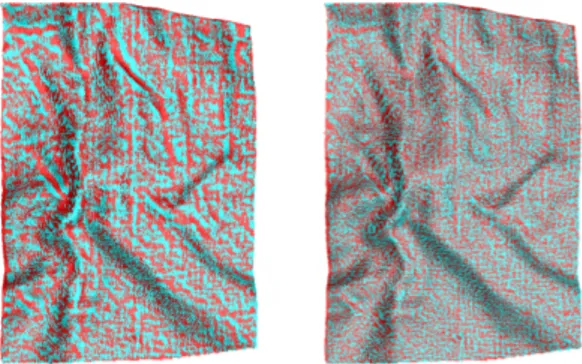
Figure 8: Alignment results for varying node densities. Left: |N| = 2400, 55 seconds. Right: |N| = 9600, 10 minutes.
5.4. Limitations and future work
The proposed approach improves upon closely re-lated techniques in terms of fitting accuracy, geomet-ric distortion, and computational performance (for big-ger datasets). However, there are also some limita-tions. One major limitation is related to the fact that the method cannot handle topological changes, such as an opening mouth. This is mostly due to the adopted formulation for the smoothing energy that constraints neighbor nodes to deform similarly, as well as due to the interpolation policy adopted. A possible way to com-pensate for this would be to include the interpolation weights in the error functional, modifying their compu-tation so that they can convey a topology-aware neigh-borhood information.
Another issue of the current approach is related to its scalability. As Figure 8 testifies, our approach could achieve an even better alignment of the Pillow dataset, but the increased number of nodes noticeably increase its computational cost. A possible solution would be a more efficient error-driven node placement or refine-ment: Through the estimate of an average error asso-ciated to each node, one could locate which areas of the surface need a greater node density, and only refine the discretization there, rather than imposing a uniform node density on the entire scan. This would reduce the overall number of nodes, therefore speeding up the com-putational performance.
Finally, we would like to extend our approach in such a way as to treat multiple-view deformable registration. 6. Conclusions
In this work we presented an improved solution for the non-rigid registration of partial views which is suitable for deforming object acquisition and mod-eling, especially for high-resolution surfaces acquired
through professional 3D scanners. The method demon-strated its capability of suitably handling di↵erent de-grees of deformation for all the considered challeng-ing datasets. The selection of a denser set of corre-spondences with respect to the number of node patches defined on the surface granted our approach an im-proved accuracy with respect to state-of-the-art tech-niques for high-resolution datasets, while the adoption of a fast and robust optimization scheme, as well as a lightweight correspondence selection procedure granted satisfactory computational performance. With the com-plex of the described features, our technique is capa-ble to provide physically-plausicapa-ble, as-rigid-as-possicapa-ble deformations with accurate and e↵ective detail-aware registration properties which are valuable for many de-manding and emerging applications.
References
[1] W. Chang, H. Li, N. Mitra, M. Pauly, M. Wand, Geometric reg-istration for deformable shapes, in: Eurographics 2010 Course Notes, 2010.
[2] W. Chang, H. Li, N. J. Mitra, M. Pauly, S. Rusinkiewicz, M. Wand, Computing Correspondences in Geometric Data Sets, in: Eurographics 2011 Course Notes, 2011.
[3] O. van Kaick, H. Zhang, G. Hamarneh, D. Cohen-Or, A Survey on Shape Correspondence, Computer Graphics Forum 30 (6) (2011) 1681–1707, ISSN 1467-8659.
[4] S. Rusinkiewicz, O. Hall-Holt, M. Levoy, Real-time 3D model acquisition, ACM Transactions on Graphics 21 (3) (2002) 438– 446, ISSN 0730-0301.
[5] T. Weise, B. Leibe, L. Van Gool, Fast 3D Scanning with Auto-matic Motion Compensation, in: Proc. of IEEE Conference on Computer Vision and Pattern Recognition (CVPR), ISSN 1063-6919, 1–8, 2007.
[6] Z. Zhang, Microsoft Kinect Sensor and Its E↵ect, IEEE Multi-Media 19 (2) (2012) 4–10, ISSN 1070-986X.
[7] S. Izadi, D. Kim, O. Hilliges, D. Molyneaux, R. Newcombe, P. Kohli, J. Shotton, S. Hodges, D. Freeman, A. Davison, A. Fitzgibbon, KinectFusion: real-time 3D reconstruction and interaction using a moving depth camera, in: Proc. of ACM Symposium on User Interface Software and Technology (UIST), ISBN 978-1-4503-0716-1, 559–568, 2011.
[8] D. Hahnel, S. Thrun, W. Burgard, An extension of the ICP al-gorithm for modeling nonrigid objects with mobile robots, in: Proceedings of the Sixteenth International Joint Conference on Artificial Intelligence (IJCAI), 915–920, 2003.
[9] N. J. Mitra, S. Fl¨ory, M. Ovsjanikov, N. Gelfand, L. Guibas, H. Pottmann, Dynamic geometry registration, in: Proc. of Sym-posium on Geometric Processing, ISBN 978-3-905673-46-3, 173–182, 2007.
[10] T. Popa, I. South-Dickinson, D. Bradley, A. She↵er, W. Hei-drich, Globally Consistent Space-Time Reconstruction, Com-puter Graphics Forum 29 (5) (2010) 1633–1642, ISSN 1467-8659.
[11] M. Wand, B. Adams, M. Ovsjanikov, A. Berner, M. Bokeloh, P. Jenke, L. Guibas, H.-P. Seidel, A. Schilling, Efficient recon-struction of nonrigid shape and motion from real-time 3D scan-ner data, ACM Transactions on Graphics 28 (2) (2009) 15:1– 15:15, ISSN 0730-0301.
[12] H. Li, B. Adams, L. J. Guibas, M. Pauly, Robust single-view geometry and motion reconstruction, ACM Transactions on Graphics 28 (5) (2009) 175:1–175:10, ISSN 0730-0301. [13] L. Ikemoto, N. Gelfand, M. Levoy, A hierarchical method for
aligning warped meshes, in: Proc. 3-D Digital Imaging and Modeling (3DIM), 434–441, 2003.
[14] M. Wand, P. Jenke, Q. Huang, M. Bokeloh, L. Guibas, A. Schilling, Reconstruction of deforming geometry from time-varying point clouds, in: Proc. of Symposium on Geometric Pro-cessing Symp. on Geometric ProPro-cessing, ISBN 978-3-905673-46-3, 49–58, 2007.
[15] B. J. Brown, S. Rusinkiewicz, Global non-rigid alignment of 3-D scans, ACM Transactions on Graphics 26 (3) (2007) 21:1– 21:9, ISSN 0730-0301.
[16] T. Weise, T. Wismer, B. Leibe, L. V. Gool, Online loop closure for real-time interactive 3D scanning, Computer Vision and Im-age Understanding 115 (5) (2011) 635–648, ISSN 1077-3142. [17] V. Blanz, T. Vetter, A morphable model for the synthesis of 3D
faces, in: Proceedings of SIGGRAPH 99, Computer Graphics Proceedings, Annual Conference Series, ISBN 0-201-48560-5, 187–194, 1999.
[18] M. Pauly, N. J. Mitra, J. Giesen, M. Gross, L. J. Guibas, Example-based 3D scan completion, in: Proc. of Symposium on Geometric Processing, 23–32, 2005.
[19] A. M. Bronstein, M. M. Bronstein, R. Kimmel, Generalized multidimensional scaling: A framework for isometry-invariant partial surface matching, Proceedings of National Academy of Sciences (PNAS) 103 (5) (2006) 1168–1172.
[20] B. Allen, B. Curless, Z. Popovi´c, The space of human body shapes: Reconstruction and parameterization from range scans, ACM Transactions on Graphics 22 (3) (2003) 587–594, ISSN 0730-0301.
[21] D. Anguelov, P. Srinivasan, D. Koller, S. Thrun, J. Rodgers, J. Davis, SCAPE: Shape completion and animation of people, ACM Transactions on Graphics 24 (3) (2005) 408–416, ISSN 0730-0301.
[22] B. Amberg, S. Romdhani, T. Vetter, Optimal Step Nonrigid ICP Algorithms for Surface Registration, in: Proc. of IEEE Con-ference on Computer Vision and Pattern Recognition (CVPR), ISSN 1063-6919, 1–8, 2007.
[23] M. F. Beg, M. I. Miller, A. Trouv´e, L. Younes, Computing Large Deformation Metric Mappings via Geodesic Flows of Di↵eo-morphisms, International Journal of Computer Vision 61 (2) (2005) 139–157.
[24] H. Li, R. W. Sumner, M. Pauly, Global correspondence opti-mization for non-rigid registration of depth scans, in: Proc. of Symposium on Geometric Processing, 1421–1430, 2008. [25] Q.-X. Huang, B. Adams, M. Wicke, L. J. Guibas, Non-rigid
reg-istration under isometric deformations, in: Proc. of Symposium on Geometric Processing, 1449–1457, 2008.
[26] M. Ovsjanikov, Q. Merigot, F. Memoli, L. Guibas, One Point Isometric Matching with the Heat Kernel, Computer Graphics Forum (Proc. SGP) 29 (5) (2010) 1555–1564.
[27] Y. Lipman, T. Funkhouser, M¨obius voting for surface corre-spondence, ACM Transactions on Graphics 28 (3) (2009) 72:1– 72:12.
[28] V. G. Kim, Y. Lipman, T. Funkhouser, Blended intrinsic maps, ACM Transactions on Graphics 30 (4) (2011) 79:1–79:12. [29] R. W. Sumner, J. Schmid, M. Pauly, Embedded deformation for
shape manipulation, ACM Trans. Graph. 26 (3) (2007) 80:1– 80:7, ISSN 0730-0301.
[30] M. Botsch, M. Pauly, M. Wicke, M. Gross, Adaptive Space De-formations Based on Rigid Cells, Computer Graphics Forum 26 (3) (2007) 339–347.
[31] H. Pottmann, S. Leopoldseder, M. Hofer, Simultaneous Reg-istration of Multiple Views of a 3D Object, Archives of Pho-togrammetry, Remote Sensing and Spatial Information Sciences 34 (3A) (2002) 265–270.
[32] M. Botsch, M. Pauly, M. Gross, L. Kobbelt, PriMo: coupled prisms for intuitive surface modeling, in: Proc. of Symposium on Geometric Processing, ISBN 3-905673-36-3, 11–20, 2006. [33] J. P. Lewis, M. Cordner, N. Fong, Pose space deformation: a
unified approach to shape interpolation and skeleton-driven de-formation, in: Proceedings of ACM SIGGRAPH 2000, Com-puter Graphics Proceedings, Annual Conference Series, ISBN 1-58113-208-5, 165–172, 2000.
[34] L. Kavan, S. Collins, J. ˇZ´ara, C. O’Sullivan, Geometric skinning with approximate dual quaternion blending, ACM Transactions on Graphics 27 (4) (2008) 105:1–105:23, ISSN 0730-0301. [35] S. Rusinkiewicz, M. Levoy, Efficient variants of the ICP
algo-rithm, in: Proc. of International Conference on 3D Digital Imag-ing and ModelImag-ing (3DIM), 145–152, 2001.
![Table 3: Comparison between Huang et al. [25], tested on a single-core 3.2 GHz CPU, Li et al](https://thumb-eu.123doks.com/thumbv2/123dokorg/5548749.65707/10.892.210.683.162.388/table-comparison-huang-tested-single-core-ghz-cpu.webp)