Dipartimento di Oncologia, dei Trapianti
e delle Nuove Tecnologie in Medicina
Corso di Dottorato in Tecnologie per la Salute:
Valutazione e Gestione delle Innovazioni nel Settore Biomedicale
XIX Ciclo
Ph.D. Thesis
Platforms for Prototyping Minimally
Invasive Instruments
Francesco Focacci
Ph.D. Coordinator:
Prof. Andrea Pietrabissa
Tutors:
Prof. Paolo Dario
Dr. Oliver Tonet
Acknowledgements V
Summary VII
1 Instruments for minimally-invasive surgery 1
1.1 Introduction . . . 1 1.2 History . . . 1 1.3 Laparoscopic interventions . . . 3 1.4 Mechanical manipulators . . . 6 1.5 Robotic manipulators . . . 8 1.5.1 CAD/CAM systems . . . 11
1.5.2 Surgeon aid systems, teleoperated robots . . . 13
1.6 Capsular endoscopy . . . 15
2 Design of medical mechatronic instruments 19 2.1 Introduction . . . 19
2.2 Modeling medical mechatronic instruments . . . 20
2.3 Requirements . . . 22
2.4 Rapid prototyping machines . . . 23
2.5 Introduction to real-time systems . . . 27
2.6 Different approaches for the implementation . . . 29
2.6.1 Embedded PC . . . 29
2.6.2 Single-Board Computers . . . 36
2.6.3 Microcontrollers and DSPs . . . 40
2.6.4 Real-Time PCs . . . 41
3 Development of a medical robotic platform 45 3.1 I/O Hardware . . . 45
3.1.1 Serial communications . . . 48
3.2 Real-Time part . . . 51
4.2 Evaluation of different control modes . . . 54 4.2.1 System description . . . 55 4.2.2 Performance assessment . . . 57 4.2.3 Final results . . . 58 4.3 First prototype . . . 60 4.3.1 System description . . . 60 4.3.2 Considerations . . . 66
4.4 Absolute positioning handle . . . 68
4.5 Conclusions . . . 73
5 Endoscope with enhanced resolution 77 5.1 Introduction . . . 77
5.2 Classic endoscopy . . . 77
5.3 Scientific research . . . 80
5.4 System description . . . 85
5.5 Mechanisms . . . 87
5.6 Direct and inverse kinematics . . . 91
5.7 Image processing . . . 97
5.8 Experiments . . . 99
5.9 Motor sensorization . . . 101
5.10 Conclusions . . . 105
6 Respiro. a simple breathing monitor 111 6.1 Introduction . . . 111
6.2 System description . . . 111
6.3 Experimental results . . . 116
7 Conclusions 119 A Power considerations for endoscopic capsules 123 B RTAI Linux 129 B.1 Introduction to Linux real time systems . . . 129
B.1.1 Introduction . . . 129
B.1.2 Introduction to RTAI . . . 132
B.1.3 RTAI Architecture . . . 133
B.1.4 Real-Time Application Interface . . . 133
B.1.5 The Real-Time Task . . . 134
B.1.6 Task Scheduler . . . 134
B.1.7 One-Shot and Periodic Scheduling . . . 135
B.1.8 Floating-Point Operations . . . 135
B.1.12 SMP Support . . . 136
B.1.13 Linux-RT (LXRT) . . . 136
B.1.14 POSIX Compatibility API . . . 137
B.1.15 Typical Performance . . . 137
B.2 Installing RTAI Linux . . . 138
B.3 Application example . . . 139
C Bootloader for microcontroller and DSP 143 C.1 Microchip PIC16F876 and dsPIC30F2010 . . . 143
I would like to extend my sincere thanks to Professor Andrea Pietrabissa, Professor Paolo Dario, Dr. Oliver Tonet, Dr. Giuseppe Megali and to the members of the CRIM Lab of Scuola Superiore Sant’Anna.
I would like to thank Marco Piccigallo and Claudio Quaglia that are the designers of the mechanical parts used in this work. I would like to thank also Luca Citi, Martina Marinelli, Lorenza Mattei, Filippo Cavallo, Cinzia Freschi and Stefano Sinigaglia. This work has been supported in part by the FIRB-2001 Project “ApprEndo” (no. RBNE013TYM) and by EndoCAS, the Centre of Excellence for Computer-Assisted Surgery (COFINLAB-2001 no. CLAB01PALK), both funded by MIUR, the Italian Ministry of Education, University and Research.
The introduction of new technologies in medicine is often an issue because there are many stages to go through, from the idea to the approval by ethical committees and mass production. All projects start with the problem analysis and very often in the academic field off-the-shelf solutions are not suitable. This is not only a drawback but represents a big opportunity to investigate new technological paths and to try to add new contributions to research. The first steps are related to the definition of requirements and specifications, which is one of the most time consuming parts. An in-depth technological investigation has to be carried out together with the study of commercial existing instruments, including patents, and research activities.
This work covers the first steps of the development of a medical device, dealing with the tools that can help to reduce the time for producing the laboratory pro-totype. These tools can involve electronics and software for the creation of a “uni-versal” hardware platform that can be used for many robotic applications, adapting only few components for the specific scenario. The platform is created by setting up a traditional computer with operating system and acquisition channels aimed at opening the system toward the real environment. On this platform algorithms can be implemented rapidly, allowing to assess the feasibility of an idea. This approach lets the designer concentrate on the application rather than on the selection of the appropriate hardware electronics every time that a new project starts. Requisites, specifications and components can change but the platform on which to create the prototype does not need to be modified. After completing the first prototype with external controller, the control system can be embedded: when the specifications and the components such as motors and sensors are definitive then the design of the embedded hardware can start. The designer selects a microcontroller or mi-croprocessor chip, designs the supporting electronics around it. In many cases the created instrument has to be portable and handy for the medical doctor.
This work treats the study and the development of robotic instruments for mini-mally invasive surgery (MIS). These devices have motors and sensors in close contact with the patient and that can be controlled autonomously, this means that hazards exist. Robotic systems produce large amount of heat, large voltages and movements of mechanical parts that can cause harm. The control part relative to motors move-ments or sensors reading needs to be tested. In a perfect world motors coupled with the mechanical parts as well as sensors have ideal behavior, everything that is de-signed on the paper is perfectly translated into practice. Unfortunately all the parts
to be implemented for testing purposes and if this step is not sufficient, changes in project specifications have to be performed, for instance changing actuators or sensors. It would be useful to be able to experiment different solutions just after the ending of the design phase or even better when the design phase is still running. The time needed for passing from the design to the first prototype is not negligible because often in the medical field, and particularly for minimally invasive surgery, mechanical parts are very complicated in terms of size, shape and materials. A five years period from the concept idea to the real functioning laboratory prototype is not uncommon.
The thread of this work concerns the development of robotic instruments for laparoscopy trying to obtain a platform modular, efficient and easy to use, able to deal with all the parts that compose a robotic system, such as motors, sensors and user interfaces. The aim is to speed up the very early stages of the development of a new robotic instrument. In the first part an overview of the existing instruments for minimally invasive interventions that can be found as commercial or research products is given. An introduction related to hardware electronics is presented with the requirements and the specific characteristics needed for a robotic application. The second part focuses on specific projects in MIS. The hardware used for the projects is described together with the software tools used to develop applications that manage the inputs and the outputs needed for the robotic systems and the user interfaces. Subsequent chapters describe each project in detail.
The first project concerns the study and the development of a lightweight hand-held robotic instrument for laparoscopy. Motivations are related to the lack of dexterous hand-held laparoscopic instruments. Teleoperated robotic systems bring some advantages at the cost of longer setup times and of cluttering the already crowded operating table, pushing the surgeon away from the patient: the surgeon operates at a console in a corner of the operating room and only the robot is in direct contact with the patient. Experienced surgeons tend to agree that in many procedures the benefits provided by those teleoperation systems are not really needed during the whole surgical procedure, and they tend to prefer the traditional hands-on approach for routine tasks. Led by these chands-onsideratihands-ons, the aim of this project concerns the develop of a hand-held surgical robot that can be operated by a surgeon with only one hand, while the other hand is free to use a traditional endoscopic instrument.
The second project concerns the study and the presentation of a prototype of a robotic endoscope with enhanced resolution. Visual acuity of artificial vision systems in endoscopy surgery is currently well below the human eye and this is due to the limited resolution of both cameras and displays. The application field of the system could be laparoscopic surgery, in which it achieves about 7 times higher resolution than typical commercial systems.
The third project concerns the development of a system able to detect the inspi-ration and the expiinspi-ration phases. The analysis of the breathing frequency is useful
ergonomic assessment of new surgical instruments.
Final considerations concern the approach used for the development of the proto-types. The aim is to rapidly implement and test control algorithms, virtual environ-ments and custom electronics dedicated to the instruenviron-ments. Typical microcontroller boards require less than one hour of components soldering and microcontroller soft-ware implementation requires only the time needed to write the program. The computing power of a PC is also of immediate use with the high flexibility furnished by the data acquisition boards used for the projects. The main advantage is the pos-sibility to concentrate efforts on application development without worrying about the hardware.
Instruments for minimally-invasive
surgery
1.1
Introduction
Laparoscopic surgery has had one sensitive increase in the last ten years. In 1992 the 70% of the interventions to the gall bladder in the United States, Europe and in Japan were carried out with the laparoscopic technique. The fundamental advan-tages, respect to classic surgery, are constituted by a minor post-operative trauma and a better recovery time. The patients have contributed in a meaningful way to the success of such technique, in fact it has been an increasing demand on dealing the pathologies with mimimally invasive techniques. Unfortunately the costs are not diminished with the advent of laparoscopy. Moreover the surgeon has lost skill, tactile feedback and a perfect coordination between hands and eyes, peculiarities that the surgeon had with the traditional techniques. These problems are due to the construction of laparoscopic instruments. The studied solutions in order to try to improve the laparoscopic instruments are essentially two: the development of flex-ible mechanical instruments and the study of computer-assisted devices and surgeon aid-systems. With these last systems the surgeon works to an interface while the tip follows its movements or executes predetermined actions in an autonomous way. The computer-assisted instruments are often cumbersome and much expensive, for which theirs use it is limited some surgical fields. In the next few years, probably, we will assist to the substitution of the rigid laparoscopic instruments with new ones that, thanks to the computer aid, will allow the surgeon to gain sensibility through force feedback, at the same time with lower costs and an easy way to sterilize, to transport and to prepare [5].
1.2
History
The history of laparoscopic surgery begins perhaps with the first speculum, the rectal one, invented from Ippocrate (460-375 a.c.), which dealt some internal pathologies
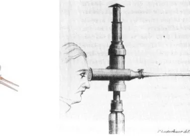
with minimally invasive techniques. The speculum is an instrument that is used in order to watch inside of cavity, and is constituted from two or three metallic sheets, that concur to delicately spread the tissues. In the ruins of Pompei a three valve copy was found, demonstrating the interest of the doctors for the study of inner organs. The true endoscopy begins with the Filippo Bozzini’s invention (1773-1809). He developed an apparatus, called “Lichtleiter”, that allowed to illuminate in indirect way the tip of the instrument and to bring back the image to the examiner’s eye. The apparatus of Bozzini never had clinical employment for rivalry within the Medical Academy of Vienna, in which the instrument was introduced.
Figure 1.1. Lichtleiter Endoscope
From Boston, John D. Fisher (1798-1850) described an endoscope, used initially for the vagina, but subsequently modified for the exploration of the bladder. In 1853, a French surgeon, Antoine Jean Desormeaux, first employed the Bozzini’s Licthleiter on a patient. The instrument, through a series of mirrors carried the light of a flame, obtained from the combustion of alcohol and turpentine. The instrument therefore reached very hot temperatures and burns were the more frequent complications, for this the employment was limited. After the discovery of the incandescence bulb Maximilian Nitze (1848-1906) elaborated some changes to the Bozzini’s endoscope but only in 1883 Newman, in Glasgow, succeeded to insert in the endoscope tip one miniaturized light bulb. In 1901, George Kelling, surgeon in Dresda, coined the term of “coelioscopie”, in order to indicate the technique that allowed to examine to the abdominal cavity of some dogs using a cystoscope. Kelling obtained a pneumoperi-toneal insufflating air through a sterile gauze filter. In literature it is unknown if he never employed this technique on the man. To the end of 1910 in Stockholm HC Jacobaeus published in the review Munchener Medizinische Wochenschrift an article on the employment of the “laparothorakoskopie”, in which an endoscope instrument was employed also in the thorax. Kelling and Jacobaeus contended for the pater-nity of the instrument and its employment, even if Kelling never did not succeed
to demonstrate to have really practiced it on the man. In John Hopkins Hospital, Bertram M. Berheim become acquainted of the studies of Jacobaeus and Kelling and he performed the first laparoscopy intervention in the United States, using, in 1911, a proctoscopio. A radiologist named Eight Goetzes developed an instrument for the creation of the pneumoperitoneus, and he predicted the use of it in laparo-scopic field. In 1920 B.H.Orndoff, internist in Chicago, reported the first series of 45 cases of diagnostic peritoneoscopies, and he invented a trocar with a trunk of cone head. In the same period the applications and the innovations were succeeded. Heinz Kalk, founder of the German school of Laparoscopy, in 1929 introduced an endoscope with 135 degrees lens and an access with multiple trocar. J.C.Ruddok, internist, developed a pliers able to coagulate. In 1938 the hungariam Janos Veress developed a needle with a safe head, that had conceived for practising the therapeu-tic pneumothorax in the tuberculosis. He used it in over 2000 cases, but he never suggested the employment of it in laparoscopy. In 1944 Raoul Palmer effected the first pelvic exploration for the study of uterus and ovaries, employing the position of Trendelemburg. The most important invention was perhaps made by Harold H. Hopkins, after 1945 and concerned optical fibers and cylindrical lenses. From that moment, for over 40 years the laparoscopic field was almost exclusive appanage of gynecologists and internists. In 1966 Kurt Semm, German gynecologist, invented the automatic insufflator and performed numerous interventions on the pelvis with laparoscopic technique. Semm also performed an appendectomy that was judged too much dangerous from the German academy of Medicine that expelled him. In the United States Semm had the opportunity to operate and to invent numerous tools for laparoscopic use.
1.3
Laparoscopic interventions
Currently the laparoscopic technique consists in the use of stiff and long instruments to effect the intervention: dissectors, forceps, hooks, pliers and clip appliers. These are inserted in the abdomen sliding them inside the trocars, after having “inflated” the abdominal cavity and made small incisions. Another important tool is the en-doscope that, once introduced in the abdomen through a small incision, it transmits the bidimensional images of the organs on a video screen. There are endoscopes that have mounted ccd sensors that capture in digital format the image carried by the optical lenses. There are also endoscopes with the ccd sensor mounted on the distal part making unnecessary the use of the optical lenses. The surgeon can see the surgical field through a dedicated monitor. The other necessary tools are:
• a carbonic anhydride insufflator and an insufflator (Veress needle) needle to induce the pneumoperitoneus, this for inflating the abdominal cavity;
• a “cold light” bright source to bring the light on the laparoscope tip;
• special tools for irrigation and aspiration, useful when it is necessary to dampen the zone to be treated or to inhale possible losses of blood;
Figure 1.2. Single use dilating trocar
• electrocoagulation, for suturing the smaller vases;
• the trocars (with valves), through which introducing the tools.
The term “trochar” was coined in 1706; it derives from French “trois” (three) + “carre” (side). The trocar is a hollow cylinder with a sharply pointed end, often three-sided, that is used to introduce laparoscopic instruments into body cavities. The trocar is a portal for the subsequent placement of other instruments, such as a forceps, clip appliers etc (in Fig. 1.3 are represented some laparoscopic instruments). In the operating room there two columns are attached to the ceiling, one for every side of the operating table. There is also a display commanded by the surgeon with which he checks all the desired parameters. The most important interventions performed with laparoscopic techniques are:
• cholecystectomy; • nephrectomy;
• adrenal gland removal; • left pancreas removal; • appendectomy;
• inguinal hernia;
• gastro-esophageal reflux desease; • cardio-thoracic surgery.
Figure 1.3. Laparoscopic instruments
1.4
Mechanical manipulators
The development of mechanic instruments able to give to the surgeon more degrees of freedom than traditional laparoscopic instruments is still evolving in the study of devices that are more coherent with the needs of the physician. It is not in fact necessary for example to have great orientation angles in all the directions. The tendency is to project mechanical manipulators that are simple to use and to maintain. We can identify which are the fundamental characteristics( [21]):
• diameter analogous to the commonly used laparoscopic instrumentation; • instruments that are simple to sterilize;
• low cost;
• easy to use for the surgeon; • affordable;
• possibility to connect with high frequency electrocauterizing instruments. In some scientific articles are presented mechanical manipulators with deflectable tip. For instance in [21] it is described an endoscopic instrument that has the char-acteristic to have a deflectable articulation among ±60◦. The tip is tilted through a handle with a sphere joint which rotates and transmits the motion to the final link. The system is entirely mechanic with cables that allow the articulation to steer. In this project the authors have focused their work on the possibility to simply clean and use it, considering that it exists only one command for orientation and rotation around the instrument axis. A further work is reported in [42], in which the authors have studied a support system for laparoscopic instruments. This allows to sustain all the instruments used by the surgeon. The system is integral with the operating table and in the point in which the single device is fixed it is present a “ball trocar” with an adjustable clutch. This allows the surgeon to regulate all the instruments in the desired position without the necessity to free them or to block them every time that are moved. In [42] it is developed a mechanical manipulator that consists of a handle inspired to the instruments used for open surgery. In fact the ergonomic principle is to transmit the movements of the surgeon’s wrist to the deflectable tip. The critical aspects concern the precise transmission of the tip rotation: this requires rigidity to always give the feeling of immediateness in the control. The complete system (support system and manipulator) allows to have six degrees of freedom.
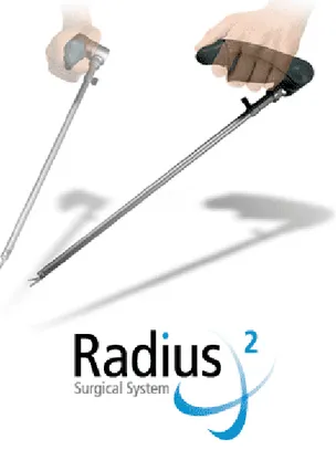
In commerce there are some devices that have a steerable tip. These are normal laparoscopic instruments to which it is added a mechanical mechanism that allows to earn two degrees of freedom (see Fig. 1.7). Another example of mechanical ma-nipulator is the Radius Surgical System from Tuebingen Scientific Medical GmbH that has been designed to dramatically improve endoscopic suturing and other sur-gical maneuvers. Instruments with mechanical driving are not intuitive since the
(a) (b)
Figure 1.5. Support system described in [42](a) and ball trocar detail (b)
Figure 1.6. Radius Surgical System
mapping of degrees of freedom (DOFs) has to respect mechanical constraint and cannot be designed freely.
The development of the mechanical manipulators for endoscopic surgery seems to be interesting. Such tools can constitute a valid alternative to the robotic ma-nipulators in applications where a microsurgery manipulation is not necessary and traditional rigid instruments are not completely satisfactory. The sphere of use could
Figure 1.7. ENDOPATH ETS-Flex Articulating Endoscopic Linear Cut-ters by Johnson & Johnson
Figure 1.8. Neuromate by Integrated Surgical System
regard laparoscopic procedures for urological, gynecological and digestive tract.
1.5
Robotic manipulators
The use of robots in surgery is still been having a development from the half of the eighties. The number of robotic systems studied and developed in research fields is higher in comparison to the commercial offer. The advantages of a robotic system concern the accurate positioning, the ability to perform difficult trajectories and the repeatability of the movements. There is also the possibility to limit the use of the robot to a “safe” area for the patient [11]. The first robot interventions were carried out for neurosurgery applications and consisted in instrument positioning on the skull and then in instrument insertion to reach the area of interest inside the brain. A recent example of such type of system is the Neuromate (http://www.robodoc.com/) by Integrated Surgical System, that is used for neurosurgery (see Fig. 1.8). The robot is switched off after the positioning task and the physician can proceed with the manipulation of the instrument located at the end of the robotic arm (powered robot but passively used).
A different approach is constituted by the active robots that have a great con-struction complexity because they are in direct contact with the patient and they interact with him [18], in fact they continue to be operating during the whole in-tervention. Today this is the most used design and construction approach. Surgical robots can be classified in various ways, according to the design characteristics, to the degree of autonomy, to the anatomical district in which they can work or to the surgical technique. One possible classification can be made on the role of the robot inside the integrated surgical system [45]:
• CAD/CAM Surgical Systems; • Surgeon aid systems.
For the first ones there is an integrated approach that expects a preoperative plan-ning with integration and use of bi-dimensional or three-dimensional images together with other data relative to the patient. The aim is to recreate a model of the patient that can be used by the computer using images and other anatomical informations. In the operating room, during the intervention, there is the registration of the created model using on line data measured at the moment through a localization system: infrared, X rays or ultrasounds. Subsequently the surgical plan update is performed with the verification that the robotic procedure is correct, and after this phase the intervention is carried out. The difficulties of such procedure concern the different typologies of images to integrate (X rays, magnetic resonance, echography, etc.), preoperative as well as intra-operative. A suitable calibration is necessary to get good results in terms of precision and accuracy. Neuromate is an example of such category of systems. The aim of surgeon aid systems is to improve ergonomics in laparoscopic surgery and to give to the physician additional functionalities and abil-ities with respect to the traditional laparoscopic procedures. The application fields of such systems concern laparoscopy and microsurgery. An example is constituted by the “assistant” robot AESOPr that is able to sustain the endoscope and to direct it according to the directives transmitted by the surgeon with the voice (see Fig. 1.9). AESOP has a kinematic architecture with a passive remote center of mo-tion (RCM), in fact the insermo-tion point of the trocar into the patient, called pivot, is used to orient the endoscope. Such robot is composed from the first three active joints and from the last two passive rotational joints. The rotation is possible thanks to the constraint constituted by the pivot point. Other robots have different active RCM architecture, due to the different kinematic project; the rotation around the pivot is performed thanks to a parallelogram mechanical structure. Other examples of surgeon aid systems are constituted by teleoperated systems that usually have more capabilities than AESOP. They replicate the movements made by the surgeon augmenting his capabilities. A further classification can be made on the degree of “intelligence” of the system [16]:
• Hand-Held instruments;
Figure 1.9. AESOP by Computer Motion
• Autonomous surgical robots for minimally invasive surgery.
Hand-held instruments are instruments guided from the surgeon’s hand and they are able of augmenting surgeon’s capabilities, correcting his actions, amplifying or diminishing the interaction with the surgical field or restoring degrees of freedom. Hand-held instruments can be mechanical or mechatronic, for the last ones there are many research studies even if these are not still been using in the clinical practice. An example of hand-held mechatronic prototype is described in [13] and [17]. This instrument has been developed for arthroscopy and has one cable actuated steerable tip and incorporates sensors for tip position monitoring and for contact monitoring with surrounding tissues. The main feature of this arthroscope is that it is possible to implement a semi-automatic procedure in order to avoid contacts between the tip and delicate tissues like cartilages and ligaments that are selected during the preoperative phase. The complete system expects the construction of a model with diagnostic images that are used in the operating room and matched with the intra operative instrument localization. Micron [2] is another example of mechatronic instrument (see Fig. 1.10) and is designed in order to eliminate the surgeon’s hand tremor in ophthalmological surgery. Equipped with an accelerometer and three gyroscopes it can reduce the tremor of 45% in monodimensional tests and 37% in three-dimensional tests. Teleoperated robotic systems are composed by two unit: the master, in which the surgeon operates and the slave, that is in direct contact with the patient. The surgeon carries out the tasks at the master console while the slave unit follows the movements of the surgeon. Finally the autonomous systems are able to carry out tasks without the participation of the surgeon. The tasks are well planned during the preoperative phase. Teleoperated and autonomous systems will be described more in detail later.
Figure 1.10. Micron
Figure 1.11. ROBODOC by Integrated Surgical System http://www.robodoc.com/
1.5.1
CAD/CAM systems
CAD/CAM and autonomous systems have functional analogies that concern the planning phase of the surgical intervention. As already pointed out the analogies are based on the integration of the 2-D and 3-D preoperative images with intra oper-ative data. CAD/CAM systems constitute a category that can include autonomous systems in which the idea is to place the robot and then start the procedure that is executed autonomously by the robot while the surgeon monitors the procedure. The fields of application of these systems are those in which there are fixed structures like as an example in neurosurgery and orthopedic surgery. The surgeon plans during the preoperative phase the task that the robot will have to execute. ROBODOC by Integrated Surgical System (see Fig. 1.11) and CASPAR by U.R.S.-Ortho are examples of such type of systems and are used respectively for femur and knee in orthopedic surgery. The limb of the patient is fixed in a prearranged position and
Figure 1.12. CyberKnife by Accuray
therefore the cut of the bone can start. Recently a new system for orthopaedic surgery has been developed from the KAIST (South Korea), this is called Arthro-bot and works on the femur. Although it has not been still used on real patients the experimental results are remarkable in terms of error and contact surface. Cy-berKnife (http://www.accuray.com/) by Accuray (see Fig. 1.12) is another example and is used for robotic radiosurgery.
On the robotic arm is mounted a linear accelerator and the system is designed to treat tumors anywhere in the body with sub-millimeter accuracy. Using image guidance technology and computer controlled robotics, the CyberKnife is designed to continuously track, detect and correct for tumor and patient movement through-out the treatment. Because of its extreme precision, the CyberKnife does not require invasive head or body frames to stabilize patient movement, vastly increasing the system flexibility. Unlike traditional radiosurgery systems that can only treat tumors in the head and neck, the CyberKnife can treat both intracranial and extracranial tumors. Other applications include spine, lung, prostate, liver and pancreas tumor. The autonomous systems for deformable organs endoscopy constitute an optimal op-portunity in order to perform minimally invasive interventions in organs that vary their dimension. Preoperative images are not always reliable in order to take deci-sions on the intervention, it can be useful to have an autonomous robot that is able to interact with the environment. Cardiovascular catheters do not fall properly in this category even if they have been equipped with therapeutic instruments, sensors and shape memory materials in order to implement an active guidance system. The catheters in fact are controlled directly from the surgeon. In CAD/CAM category there are also robotic systems that can support and position an instrument that is in direct contact with the patient and the instrument is controlled directly by the sur-geon. The instrument handle is situated at the end of the robot and is equipped with force sensors in order to follow the movements made by the surgeon. ACROBOT by ACROBOT Company (see Fig. 1.13) is another example of such robot systems and is designed to carry out knee prosthesis implant intervention. The active robot is
Figure 1.13. ACROBOT by ACROBOT Company
located at the end of the positioning system and is controlled by the surgeon. The operative workspace is confined, by hardware and software, to a certain volume in space. The device does not move autonomously, although it could be programmed to do so; it reacts to the actions of the surgeon holding the handle attached to the device. It aids motion, if the surgeon is moving the tool inside an allowed spatial volume; it prevents motion outside this volume called safety area.
The “active constraints” are defined in the preoperative phase, those zones can-not be reached from the instrument. Moreover the best robot positioning is decided also in this phase.
1.5.2
Surgeon aid systems, teleoperated robots
Teleoperated master-slave manipulators have the “master” console at which the surgeon works, while the “slave” part acts directly on the patient. Such type of approach is an open-loop control, closed from the surgeon through the display view. The tools on which the surgeon acts can be joysticks or ergonomic grips in order to simulate an instrument (see Fig. 1.14).
In commerce two products exist that operate with the master-slave modality: the ZEUS system by Motion Computer (see Fig. 1.15) and the daVinci surgical system by Intuitive Surgical Inc. (see Fig. 1.16). The master console of the daVinci surgical system (see Fig. 1.14) is composed by two grips that are used to read the position of the surgeon’s hands and to map their position with the “endowrist” position in the slave part. The two “endowrists” are the end effectors of the robot. The endoscope has two integrated optical systems are used to reconstruct a three-dimensional image in the monitor of the master console. The vision cone is less than the one offered by a single optical endoscope.
Many teleoperated robot projects were aimed at the possibility to allow teleop-erated interventions. The surgeon seat to the master console that could be in a
Figure 1.14. Master console of daVinci surgical system by Intuitive Surgical Inc.
Figure 1.15. ZEUS system
different place from that of the slave part and a remote connection is established between the two part of the robot. The delay time and the possible interruptions on the remote connection led to neglect the teleoperated interventions in favor of ma-jor ergonomics obtainable with master-slave robotic systems. Laprotek system by endoVia Medical (endovia.millersystems.com) is another system formed by a mas-ter console separated from the slave part (see Fig. 1.17). Compact drive units are attached to the sides of the operating table during use and are connected to the surgical arms by a cable mechanism that eliminates the need for electrical connec-tions between the surgical arms and the computer control system. Sensors on the drive motors provide force feedback to the surgeon’s control handles, thus providing tactile clues to help the surgeon manipulate the instruments.
There are also mechanical teleoperated systems and in particular in [26] is de-scribed a system for the control of two seven degrees of freedom endoscopic instru-ments (see Fig. 1.18). The system is fixed at the operating table, the surgeon is sitting and through the grips transfers the movement to the tip of the instruments.
Figure 1.16. daVinci surgical system by Intuitive Surgical Inc.
Figure 1.17. Laprotek system by endoVia Medical
A monitor is placed in optimal direction for the surgeon. The surgeon’s hands are always held in a parallel position respect to the tip instruments position.
1.6
Capsular endoscopy
Semiautomatic endoscopes represent a step ahead because they can move in small spaces with arbitrary directions. Their locomotion is worm like. The endoscope presented in [14], in [15] and in [39] are examples of this approach. Three types of autonomous robots for colonoscopy have been studied at Korea Institute of Science
Figure 1.18. Mechanical teleoperated manipulator [26]
and Technologies: one uses wheels in order to move; the second uses a pneumatic actuator [60] while the third uses a millepede inspired locomotion [10].
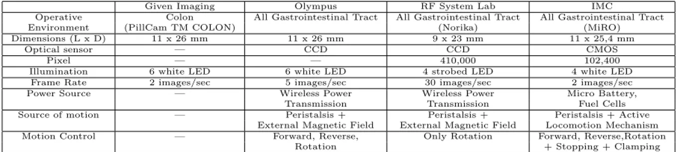
The studies carried out on pills for endoscopic exploration represent a further step. Capsules are miniaturized instruments for colon inspection and they are pow-ered by batteries. Two commercial pills exist, one from Olympus and the other from Given Imaging (see Fig. 1.19). The main capsules project specifications are reported in Tab 1.1. Many research works are involved in the study of legged en-doscopic capsules as the one presented in [43], able to move by means of legs. The contact between the leg and the tissue allows the capsule to slide inside the colon.
(a) (b)
Given Imaging Olympus RF System Lab IMC
Operative Colon All Gastrointestinal Tract All Gastrointestinal Tract All Gastrointestinal Tract Environment (PillCam TM COLON) (Norika) (MiRO) Dimensions (L x D) 11 x 26 mm 11 x 26 mm 9 x 23 mm 11 x 25,4 mm
Optical sensor — CCD CCD CMOS Pixel — — 410,000 102,400 Illumination 6 white LED 6 white LED 4 strobed LED 4 white LED
Frame Rate 2 images/sec 5 images/sec 30 images/sec 2 images/sec Power Source — Wireless Power Wireless Power Micro Battery,
Transmission Transmission Fuel Cells Source of motion — Peristalsis + Peristalsis + Peristalsis + Active
External Magnetic Field External Magnetic Field Locomotion Mechanism Motion Control — Forward, Reverse, Only Rotation Forward, Reverse,Rotation
Rotation + Stopping + Clamping
Design of medical mechatronic
instruments
2.1
Introduction
The requisites for a general purpose “rapid prototyping platform” are pointed out in this chapter together with a list of possible technological solutions. Prototype fabrication is one of the most important step in every research project because it is required in order to test the goodness of the hypothesis or to investigate new solutions. It would be useful to prove the feasibility of a project in very short time from the concept idea to the first prototype. The development phases of a new medical instrument are presented in Fig. 2.1 and it is not uncommon that the first three phases occupy on third of the scale. Software an hardware tools can be considered for accelerating the development process, they can be used for simulation as well as for data acquisition. Mechanical design software tools are not analysed in this work, that is more oriented to electronics aspects. Model characterization of the system is very important in order to perform simulations and therefore the tuning of system parameters. MATLAB is one of the main software tools used for simulation, it has great capabilities in terms of mathematical computations. Typical application fields are signal and image processing, statistical elaboration and simulation of complex control algorithms. Scilab (www.scilab.org) is an open-source software used for numerical computations and control applications. Specific toolboxes are available for classic and robust control, data interpolation, graphics and others. Simulation is very important for having a rough estimation of the behavior of the system that will be fabricated. The next step is the prototype fabrication: this is one of the most time consuming phases because mechanical parts require the use of machinery and skilled labour. Rapid prototyping machines represent a valid option for the prototype development. They accept in input CAD drawings and produce in output the mechanical part made of resin or other materials in short time, they create physical models directly from digital data in hours instead of days.
Lab prototype 1st Customer Trials FDA Approval α and β testing Concept Feasibility Manufacture Start Mass Production ph as es years 0 5 10 15
Figure 2.1. Instrument development phases.
As a drawback the mechanical parts produced are not very strength and they can only be used for the very “first prototype”.
The control unit is the system “brain” and his task is to coordinate appropriately all the system components with the aim to ensure the correct behavior of the device. The controller can be implemented in simulation environment bu the validation phase can be performed only when mechanical system is built and actuators and sensors are chosen.
2.2
Modeling medical mechatronic instruments
Medical mechatronic instruments can be modeled using the scheme depicted in Fig. 2.2. Mechatronics is defined as the integration of methodologies and tech-niques coming from different fields like mechanical and electronic engineering and computer science. Deep integration of the fundamental components like mechanical parts, sensors, actuators, controllers and power supply has to be taken into account in the instrument design phase. In traditional industrial environment, robots are programmed to complete tasks with no human interaction. Medical robotic instru-ments have to be safe enough to allow the interaction with tissues and organs.
The power supply is located at the centre of the diagram in Fig. 2.2 because it has to provide energy to all the system components. Low energy sources must be employed when in contact with patients, isolating the high energy part from the low energy, depending from the micro-shock or macro-shock risks. Moreover in autonomous medical robots the available power is very low, like in capsular en-doscopy in which images acquisition is required, maybe in some cases together with locomotion fighting with small sizes and therefore small batteries.
The control unit is the core of the mechatronic system since it generates suitable signals for the actuators after reading sensors. Low-level controller are more related to the hardware: for example the motor positioning calculations must be performed by the low-level control because several timing constraints exist. Graphical user interfaces or more abstract algorithms can be delegated to the high-level control that
Mechanisms Actuators Sensors Power Supply Control Unit User Interface H uma n E nv iro nme nt W or kin g S pa ce
Figure 2.2. Generic robotic instrument schematic.
has to perform a high number and often more complex calculations with less timing constraints. The more the task complexity arises the less the timing constraints will be narrow.
Control systems are used to regulate an enormous variety of machines, products, and processes. They control quantities such as motion, temperature, heat flow, fluid flow, fluid pressure, tension, voltage, and current. Most concepts in control theory are based on having sensors to measure the quantity under control. In fact, control theory is often taught assuming the availability of near-perfect feedback signals. Unfortunately, such an assumption is often invalid. Physical sensors have shortcomings that can degrade a control system. There are at least four common problems caused by sensors. First, they are expensive and this can substantially raise the total cost of a control system. In many cases, the sensors and their associated cabling are among the most expensive components in the system. Second, sensors and their associated wiring reduce the reliability of control systems. Third, some signals are impractical to measure. The objects being measured may be inaccessible for such reasons as harsh environments and relative motion between the controller and the sensor (for example, when trying to measure the temperature of a motor rotor). Fourth, sensors usually induce significant errors such as stochastic noise, cyclical errors, and limited responsiveness. Every prototype, in medical robotics as well as for other fields, needs motors that have to be powered and sensors that have to be read. Many data acquisition systems exist and they can be combined in many configuration. Personal computers with data acquisition electronic boards can be useful instruments for testing control strategies, data monitoring, user interfaces but they can be used only in a research environment. Deeply embedded systems
have microcontrollers or DSPs (DSP Digital Signal Processor) that perform rapid calculation dedicated to the instrument behavior. When a system is fully developed and tested it is possible to port its “operating system” from the testing platform to an embedded hardware.
2.3
Requirements
The requirements for a mechatronic prototyping platform are related to the flex-ibility. In many cases we may not known the exact configuration of the system. In chapter 5 the bioinspired endoscope is described and the relative motor driver board gives back an impulse every time that the motor performs a revolution. This measure is not affordable anymore because it is not based on “real” position sen-sors but on counter-electromotive voltage that is generally used for low-cost position sensing. This problem can be overcame by adding two sensors and therefore two additional signals to have to be read and processed. The detail of this project are reported in chapter 5. This example has highlighted the need for very flexible acqui-sition systems. General Data Acquiacqui-sition board (DAQ board) are very important because they have a great number of digital input/output channels, analog input channels and counters/timers and analog output channels. Analog inputs usually are specified as single-ended or differential input channels. Single-ended (SE) chan-nels share the same ground point. Differential inputs (DE) have different reference points for each input, and therefore need two channels. In general, SE channels are appropriate when the input signals are greater than 1 V, the signal source is not so far in terms of distance, and all inputs share a common reference. DE inputs have better noise immunity and typically prevent ground loops. While not strictly part of data acquisition, many products offer analog outputs on the same board. In almost all cases, a data acquisition board has either 2 or 4 outputs. If more are needed, a dedicated analog output board may be required. A somewhat separate class of digital I/O is pulse inputs and outputs, which typically is associated with frequency, counting, or totalization applications. Pulse inputs might be used to count the rotations of a turbine flowmeter; pulse outputs might be used to drive a stepping motor. Counter/timer channels are very useful in order to interface with motor encoders or to generate pulse trains or pulse width modulated signals. Pulse inputs are handled in the same way as digital logic inputs, but the output of the sensing circuit is normally connected to a counter rather than a specific bit position in the input register. Successive pulses increment or decrement the counter. Add an elapsed time measure and a frequency or pulse rate can readily be determined.
All these features can be found in microcontrollers or in DSPs but for these devices a deep knowledge of the internal architecture, the programming language like assembler is necessary. PCI DAQ boards represents another possible solution, they are plugged in a traditional PC on the PCI bus and they can be accessed for reading all the input/output channels using libraries supported in C/C++ programming languages. In this case the traditional tools for software development like Visual
Studio with C++ programming language can be used for accessing the DAQ board and implement the board registers reading or writing. Often the DAQ boards have special features that allow to acquire samples using the on-board clock and to write the samples in a buffer that the user can access through software. This feature is very important because the operating systems like Windows or Linux are not real-time operating systems and they can not guarantee the timing requirements for sampling. Real-time operating systems are used in industry for controlling robots or other machines and they are generally commercial. Free real-time operating systems exist, they are in tight relationship with the used hardware, therefore the user must deeply know the structure of the operating system and how it operates to customize it. Implementing the control of a robotic system with a Windows based PC it is not a correct approach because robots have very narrow timing constraints. Code Development on a Windows based PC is suitable for implementing high-level control algorithms in which timing constraints are not very narrow and in which great complexity exists, while the real-time operations have to be delegated to specific hardware.
2.4
Rapid prototyping machines
Rapid prototyping is the name given to a host of related technologies that are used to fabricate physical objects directly from CAD data sources. These methods are unique in that they add and bond materials in layers to form objects. Such systems are also known by the names additive fabrication, three dimensional printing, solid free form fabrication and layered manufacturing. They offer advantages in many applications compared to classical subtractive fabrication methods such as milling or turning:
• Objects can be formed with any geometric complexity or intricacy without the need for elaborate machine setup or final assembly;
• Objects can be made from multiple materials, or as composites, or materials can even be varied in a controlled fashion at any location in an object;
• Additive fabrication systems reduce the construction of complex objects to a manageable, straightforward, and relatively fast process.
These properties have resulted in their wide use as a way to reduce time to market in manufacturing. Today’s systems are heavily used by engineers to better understand and communicate their product designs as well as to make rapid tooling to man-ufacture those products. Surgeons, architects, artists and individuals from many other disciplines also routinely use the technology. The names of specific processes themselves are also often used as synonyms for the entire field of rapid prototyping. Among these are stereolithography (SLA for stereolithography apparatus), selective laser sintering (SLS), fused deposition modeling (FDM), laminated object manufac-turing (LOM), inkjet-based systems and three dimensional printing (3DP). Each of
these technologies and the many other rapid prototyping processes has its singular strengths and weaknesses. Stereolithography is the most widely used rapid proto-typing technology, it builds plastic parts or objects a layer at a time by tracing a laser beam on the surface of a vat of liquid photopolymer. This class of materi-als, originally developed for the printing and packaging industries, quickly solidifies wherever the laser beam strikes the surface of the liquid. Once one layer is com-pletely traced, it’s lowered a small distance into the vat and a second layer is traced right on top of the first. The self-adhesive property of the material causes the layers to bond to one another and eventually form a complete, three-dimensional object after many such layers are formed. Some objects have overhangs or undercuts which must be supported during the fabrication process by support structures. These are either manually or automatically designed and fabricated right along with the ob-ject. Upon completion of the fabrication process, the object is elevated from the vat and the supports are cut off. Stereolithography generally is considered to provide the greatest accuracy and best surface finish of any rapid prototyping technology. Over the years, a wide range of materials with properties mimicking those of several engineering thermoplastics have been developed. Limited selectively color changing materials for biomedical and other applications are available, and ceramic materials are currently being developed. The technology is also notable for the large object sizes that are possible. On the negative side, working with liquid materials can be messy and parts often require a post-curing operation in a separate oven-like apparatus for complete cure and stability.
SLS technology uses thermoplastic powder that is spread by a roller over the surface of a build cylinder. The piston in the cylinder moves down one object layer thickness to accommodate the new layer of powder. The powder delivery system is similar in function to the build cylinder. Here, a piston moves upward incrementally to supply a measured quantity of powder for each layer. A laser beam is then traced over the surface of this tightly compacted powder to selectively melt and bond it to form a layer of the object. The fabrication chamber is maintained at a temperature just below the melting point of the powder so that heat from the laser need only elevate the temperature slightly to cause sintering. This greatly speeds up the process that is repeated until the entire object is fabricated. After the object is fully formed, the piston is raised to elevate it. Excess powder is simply brushed away and final manual finishing may be carried out. No supports are required with this method since overhangs and undercuts are supported by the solid powder bed. It may take a considerable length of cool-down time before the part can be removed from the machine. Large parts with thin sections may require as much as two days of cooling time. SLS offers the key advantage of making functional parts in essentially final materials. However, the system is mechanically more complex than stereolithography and most other technologies. A variety of thermoplastic materials such as nylon, glass filled nylon, and polystyrene are available. Surface finishes and accuracy are not quite as good as with stereolithography, but material properties can be quite close to those of the intrinsic materials. The method has also been extended to provide direct fabrication of metal and ceramic objects and tools. Since
the objects are sintered they are porous. It may be necessary to infiltrate the part, especially metals, with another material to improve mechanical characteristics.
FDM is the second most widely used rapid prototyping technology, after stere-olithography. A plastic filament is unwound from a coil and supplies material to an extrusion nozzle. The nozzle is heated to melt the plastic and has a mechanism which allows the flow of the melted plastic to be turned on and off. The nozzle is mounted to a mechanical stage which can be moved in both horizontal and verti-cal directions. As the nozzle is moved over the table in the required geometry, it deposits a thin bead of extruded plastic to form each layer. The plastic hardens immediately after being squirted from the nozzle and bonds to the layer below. The entire system is contained within a chamber which is held at a temperature just be-low the melting point of the plastic. Several materials are available for the process including ABS and investment casting wax. ABS offers good strength, and more re-cently polycarbonate and poly(phenyl)sulfone materials have been introduced which extend the capabilities of the method further in terms of strength and temperature range. Support structures are fabricated for overhanging geometries and are later removed by breaking them away from the object. A water-soluble support material which can simply be washed away is also available. The method is office-friendly and quiet. FDM is fairly fast for small parts on the order of a few cubic inches, or those that have tall, thin form-factors. It can be very slow for parts with wide cross sections, however. The finish of parts produced with the method have been greatly improved over the years, but are not quite on a par with stereolithography. The closest competitor to the FDM process is probably three dimensional printing. However, FDM offers greater strength and a wider range of materials than at least the implementations of 3DP from Z Corp. which are most closely comparable.
In LOM technology profiles of object cross sections are cut from paper or other web material using a laser. The paper is unwound from a feed roll onto the stack and first bonded to the previous layer using a heated roller which melts a plastic coating on the bottom side of the paper. The profiles are then traced by an optics system that is mounted to an X-Y stage. After cutting of the layer is complete, excess paper is cut away to separate the layer from the web. Waste paper is wound on a take-up roll. The method is self-supporting for overhangs and undercuts. Areas of cross sections which have to be removed in the final object are heavily cross-hatched with the laser to facilitate removal. It can be time consuming to remove extra material for some geometries, however. In general, the finish, accuracy and stability of paper objects are not as good as for materials used with other RP methods. However, material costs are very low, and objects have the look and feel of wood and can be worked and finished in the same manner. This has fostered applications such as patterns for sand castings. While there are limitations on materials, work has been done with plastics, composites, ceramics and metals. Some of these materials are available on a limited commercial basis. Variations on this method have been developed by many companies and research groups. For example, Kira’s Paper Lamination Technology (PLT) uses a knife to cut each layer instead of a laser and applies adhesive to bond layers using the xerographic process. There are
also variations which seek to increase speed and/or material versatility by cutting the edges of thick layers diagonally to avoid stair stepping.
Thermal Phase Change Inkjets uses a single jet each for a plastic build material and a wax-like support material, which are held in a melted liquid state in reservoirs. The liquids are fed to individual jetting heads which squirt tiny droplets of the materials as they are moved in X-Y fashion in the required pattern to form a layer of the object. The materials harden by rapidly dropping in temperature as they are deposited. After an entire layer of the object is formed by jetting, a milling head is passed over the layer to make it a uniform thickness. Particles are vacuumed away as the milling head cuts and are captured in a filter. The process is repeated to form the entire object. After the object is completed, the wax support material is either melted or dissolved away. The most outstanding characteristic of the Solidscape company system is the ability to produce extremely fine resolution and surface finishes, essentially equivalent to CNC machines. However, the technique is very slow for large objects. While the size of the machine and materials are office-friendly, the use of a milling head creates noise which may be objectionable in an office environment. Materials selection also is very limited. Other manufacturers use considerably different inkjet techniques, but all rely on squirting a build material in a liquid or melted state which cools or otherwise hardens to form a solid on impact. 3D Systems produces an inkjet machine called the ThermoJet Modelerr which utilizes several hundred nozzles in a wide head configuration. It uses a hair-like matrix of build material to provide support for overhangs which can be easily brushed off once the object is complete. This machine is much faster than the Solidscape approach, but does not offer as good a surface finish or resolution. All thermal phase change inkjets have material limitations and make fragile parts. The applications range from concept models to precise casting patterns for industry and the arts, particularly jewelry.
Three dimensional printing was developed at MIT. It’s often used as a di-rect manufacturing process as well as for rapid prototyping. The process starts by depositing a layer of powder object material at the top of a fabrication cham-ber. To accomplish this, a measured quantity of powder is first dispensed from a similar supply chamber by moving a piston upward incrementally. The roller then distributes and compresses the powder at the top of the fabrication chamber. The multi-channel jetting head subsequently deposits a liquid adhesive in a two dimen-sional pattern onto the layer of the powder which becomes bonded in the areas where the adhesive is deposited, to form a layer of the object. Once a layer is completed, the fabrication piston moves down by the thickness of a layer, and the process is repeated until the entire object is formed within the powder bed. After completion, the object is elevated and the extra powder brushed away leaving a “green” object. No external supports are required during fabrication since the powder bed supports overhangs. Three dimensional printing offers the advantages of speedy fabrication and low materials cost. In fact, it’s probably the fastest of all RP methods. Recently color output has also become available. However, there are limitations on resolution, surface finish, part fragility and available materials. The closest competitor to this
process is probably fused deposition modeling.
Laser Engineered Net Shapingr and similar laser powder forming technolo-gies are gaining in importance and are in early stages of commercialization. A high power laser is used to melt metal powder supplied coaxially to the focus of the laser beam through a deposition head. The laser beam typically travels through the center of the head and is focused to a small spot by one or more lenses. The X-Y table is moved in raster fashion to fabricate each layer of the object. The head is moved up vertically as each layer is completed. Metal powders are delivered and distributed around the circumference of the head either by gravity, or by using a pressurized carrier gas. An inert shroud gas is often used to shield the melt pool from atmospheric oxygen for better control of properties, and to promote layer to layer adhesion by providing better surface wetting. A variety of materials can be used such as stainless steel, Inconel, copper, aluminum etc. Of particular interest are reactive materials such as titanium. Materials composition can be changed dynam-ically and continuously, leading to objects with properties that might be mutually exclusive using classical fabrication methods. The strength of the technology lies in the ability to fabricate fully-dense metal parts with good metallurgical properties at reasonable speeds. Objects fabricated are near net shape, but generally will require finish machining. They have good grain structure, and have properties similar to, or even better than the intrinsic materials. Selective laser sintering is at present the only other commercialized RP process that can produce metal parts directly. However, laser powder forming methods have fewer material limitations than SLS, don’t require secondary firing operations as some of those processes do, and can also be used to repair parts as well as fabricate them.
2.5
Introduction to real-time systems
The aim of this introduction is to give to the reader practical informations on the hardware and the software that can be used to build up a substantial control system. After some knowledges on real-time computing systems, some hardware platforms are taken into account in order to implement control systems, from microcontroller, to PC104 boards, to Single-Board Computer. These are important to build up compact and embedded systems. Linux based PCs with real-time operating systems are taken into account for the big potential represented by the possibility to have in a common desktop PC a very smart platform to test and prototype control systems for many applications. Operating system is the software component of a computer system that is responsible for the management and coordination of activities and the sharing of the resources of the computer. Real-time computing systems have the peculiarity to react within precise time constraints during the interaction with the real world. This does not means that a real-time system is fast in an absolute way but that is able to process informations from the environment in useful time to guarantee the correct functioning of the whole system. The objective of fast computing is to minimize the average response time of a given set of processes and this is not
acceptable for the real-time computing that is focused on the process deadlines observance. The average response time is not able to guarantee the individual time constraints of each process. For example if in an aircraft a process deadline is missed this may cause catastrophic consequences. A deadline is represented by the time before which a process should complete its execution. The words task and process in this work are used as synonyms and the meaning is the computation that is executed by the central processing unit (CPU) in a sequential fashion. Real-time tasks are usually distinguished in two classes:
• Hard: in which the completion after the deadline can cause catastrophic consequences. In this case any process should be guaranteed in the worst-case scenario;
• Soft: if the deadline is missed the performances of the system are decreased but the correct behavior is not compromised.
A schedule is an assignment of tasks to the processor, so that is executed until completion. More formally a schedule can be defined as a function σ : <+ → N such that ∀t ∈ <+,∃t
1,t2 such that t ∈ [t1,t1) and ∀t’ ∈ [t1,t2) σ(t) = σ(t’). In other
words, σ(t) is an integer step function and, σ(t) = k, with k > 0, means that task Jk
is executing at time t, while σ(t) = 0 means that the CPU is idle. The scheduling policy is the criterion with which the CPU is assigned to the various tasks. The scheduling algorithm is the set of rules that, at any time, determines the order in which tasks are executed. The specific operation of allocating the CPU to a task by the scheduling algorithm is called dispatching. The main algorithm classes are:
• Preemptive: the running task can be interrupted at any time to assign the processor to another active task.
• Non-preemptive: the running task, once started, is executed by the proces-sor until completion.
• Static: the scheduling decisions are based on fixed parameters, assigned to task before their activation.
• Dynamic: the scheduling decisions are based on dynamic parameters that may change during system evolution.
• Off-line: the scheduling algorithm is executed on the entire task set before actual task activation. The schedule generated is stored in a table and later executed by a dispatcher.
• On-line: the scheduling decisions are taken at runtime every time a new task enters the system or when a running task terminates.
• Optimal: the algorithm is said to be optimal if it minimizes some given cost function defined over the task set.
• Heuristic: the algorithm is said to be heuristic if it tends toward but does not guarantee to find the optimal schedule.
A real system must deal with both periodic and aperiodic tasks. Typically peri-odic tasks are related to sensory data acquisition, control loops, low-level servoing and so on, this represent the major computational demand because they have to be executed at specific rates. Aperiodic tasks are related to events called interrupts and the arrival time is unknown. In a real application it is plausible that aperiodic tasks are treated like soft tasks and periodic tasks like hard tasks under dynamic priority assignments. A resource is any software structure that can be used by a process to advance in execution and can be typically a set of variables, a data struc-ture, a set of registers or a file. The resource can be “private” when is dedicated to a particular process or “shared” when more than one task access to it. A shared resource is named “exclusive” if it is protected against concurrent accesses. A task that needs to enter in a critical section must wait that the exclusive resource be-comes “free”, otherwise it called “blocked”. An operating system provides general synchronization tool called “semaphores” that can be used by tasks to build critical section for accessing resources. Moreover there are resource access protocols in order to solve problems that arise when concurrent task use shared resources in exclusive mode and to respect the maximum blocking time for each task for ensuring the time constraints.
2.6
Different approaches for the implementation
2.6.1
Embedded PC
In the past it was more common for designers to select a microcontroller or micro-processor chip, design the supporting electronics around it and after add the special inputs and outputs required by the application. In many cases this is the optimal solution to a given problem because the design is fully customized to match exactly the project requirements. However this approach can take substantial time to get from the drawing board to the market. Reducing the time to market is one of the biggest reasons for selecting an off-the-shelf embedded PC also for medical appli-cations. In fact the core processor is already plugged in the system and integrated in a chipset. This also reduces the time spent on developing firmware, because em-bedded PCs typically already have basic input/output system (BIOS) firmware that initialize the core components, tests critical subsystems and loads the application program. All these features are present with bounded costs. Developers can base their activities on the particular application without worry about the hardware. For example today many modern medical equipment have a full-color graphical display in order to give to the user more informations and in embedded PCs there are VGA, CRT and flat-panels LCD interfaces that can be used in combination with powerful graphics softwares already available on desktop PC. The features that embedded PC share with desktop PC are (see Table 2.1):
• x86 processor.
• Chipset, including timers, direct memory access (DMA) controllers, and inter-rupt controllers.
• Serial ports. • Printer ports.
• Ethernet connection. • Video.
x86 Processor. The x86 family of microprocessors has gone through many changes since the original Intel (Santa Clara, CA) 8086 processor. From the 8086 to the 286, 386, 486, Pentium, Pentium II, Pentium III, and Pentium IV (as well as the 186 family), performance has increased exponentially over the past 20 years. In addition, other cpu manufacturers such as National Semiconductor (Santa Clara, CA), AMD (Sunnyvale, CA), and STMicroelectronics (Geneva, Switzerland) have created x86-compatible processors that have higher levels of integration or lower power consumption. However, the most important factor in determining which cpu to select is whether or not that cpu has the performance to keep up with the application. This is not a simple matter, because it is dependent on the cpu type, clock speed, and other factors such as the amount of cache and the chipset. Benchmarks are generally of little use because they rarely measure the things that are critical to a specific application. In any case, it is always a good idea to get at least twice as much computing power as is thought to be required. This allows for errors in estimation of the processor required, and it allows room to add features later. If the application requires a great deal of floating-point or long integer arithmetic, a math coprocessor is often required. It is still possible to do these calculations without a coprocessor because this can be emulated in software. However, emulation is much slower than handling these routines in hardware. Math coprocessors are standard in Intel processors from the 486DX and up (except for the 486SX, which was not widely used in embedded PCs). Processors of the 386 variety and lower require an external coprocessor. In most cases, if a coprocessor is required, a 486DX or higher is appropriate because external coprocessors are not widely available and are generally not cost-effective.
Chipset. The chipset in an embedded PC provides much of the glue logic that connects the cpu, the memory, and the I/O together in order to have a functioning PC. The chipset can be a single chip or multiple chips that are separate from the cpu, or it may be integrated into the cpu. The Intel 186 family and 386EX integrate the chipset into the processor. AMD’s Elan family, National Semiconductor’s Geode, and STMicroelectronics’s STPC similarly integrate chipset functionality into the processor. From an application standpoint, this integration does not have an effect on how development takes place. However, it can greatly reduce the number of chips

![Table 2.2. Embedded PCs extended features [29]](https://thumb-eu.123doks.com/thumbv2/123dokorg/7281173.84616/47.892.216.759.631.1038/table-embedded-pcs-extended-features.webp)