UNIVERSITY
OF TRENTO
DIPARTIMENTO DI INGEGNERIA E SCIENZA DELL’INFORMAZIONE 38123 Povo – Trento (Italy), Via Sommarive 14
http://www.disi.unitn.it
EXPLOITATION OF PARASITIC SMART ANTENNAS IN
WIRELESS SENSOR NETWORKS
F. Viani, L. Lizzi, M. Donelli, D. Pregnolato, G. Oliveri, and A. Massa
January 2011
Exploitation of Parasitic Smart Antennas in Wireless Sensor
Networks
Federico Viani, Leonardo Lizzi, Massimo Donelli, Denis Pregnolato, Giacomo Oliveri, and Andrea Massa
ELEDIA Research Group
Department of Information and Communication Technologies University of Trento, Via Sommarive 14, 38050 Trento - Italy Tel. +39 0461 882057, Fax +39 0461 882093
E-mail:[email protected], {federico.viani, leonardo.lizzi, massimo.donelli, denis.pregnolato, giacomo.oliveri}@disi.unitn.it
Exploitation of Parasitic Smart Antennas in Wireless Sensor
Networks
F. Viani, L. Lizzi, M. Donelli, D. Pregnolato, G. Oliveri, and A. Massa
Abstract
The integration of smart antennas in wireless sensor networks is a challenging and very attractive technical solution to improve the system capacity, the quality of service, and the power control. In this paper, some benefits coming from such an integration are experimen-tally assessed dealing with a set of test scenarios. Finally, some conclusions are discussed in order to point out current potentialities and limitations of the smart antennas integration to envisage future and possible advances.
1
Introduction
A Wireless Sensor Network (WSN) consists of a large number of small sensor nodes with sens-ing, data processsens-ing, and communication capabilities able to realize a distributed and remote monitoring/control of the environment. In several applications, the network nodes are ran-domly deployed, therefore the whole wireless architecture should be characterized by a highly-dynamic and reconfigurable topology with self-organizing capabilities to guarantee an energy-efficient transmission of the information on the scenario under test. Such a behavior is mainly concerned with the strategy of the medium access control (MAC) at the network layer as well as with the smart management of the physical layer to extend the node/network lifetime and to exploit the space selectivity. In this context, the adoption of a smart system (or smart an-tenna) [1][2] at the communication interface is certainly an optimal solution not only to reduce the RF-energy consumption, but also in order to maximize the efficiency of the data exchange among the network nodes. In such a way, it is possible to increase the network coverage and connectivity as well as to implement additional functionalities useful to enhance (at the physical layer) both the WSN security and privacy.
Early researches in WSNs typically considered the use of omni-directional (or isotropic) radia-tors at each node of the network architecture in order to avoid complex and expensive control systems. However, because of the potentialities of a “smart” solution in dealing with a time-varying scenario, there has recently been a growing interest in developing ad-hoc and hetero-geneous networks where some nodes are equipped with directional and adaptive antennas [3]. As a matter of fact, directional antennas (i.e., radiators able to define preferential directions of communications) have several advantages in ad-hoc networking over omni-directional radiators. For instance, they allow an enhancement of the network throughput because of a better spatial reuse of the frequency spectrum. Moreover, such systems generally provide higher signal-plus-interference-to-noise ratios (SINRs) by steering the beam pattern towards the direction of the desired signal and by placing radiation nulls along the interferers [4].
The theoretical capabilities of fully-adaptive linear or planar arrays have been analyzed in [5][6] focusing on the effectiveness of such a solution for the medium access control. However, it should be pointed out that active smart solutions (e.g., controlled phased arrays) have costs and requirements in terms of both dimensions and complexity that seem to prevent their use in today
sensor networks.
On the other hand, passive switched beam systems allow a good compromise between poten-tialities and costs for a profitable integration. As a matter of fact, they can be built using fairly inexpensive components and need of a reduced amount of space in the node structure. For such reasons, current integrations of smart antennas into sensor nodes are yielded by considering a set of multiple directional antennas with a switch control to allow the communication only in the direction identified by the activated antenna. For instance, Yang et al. proposed in [7] the use of four independent semi-directional antennas installed on the four sides of each node and controlled by a switching network. Another solution has been described in [8]. The “smart” behavior has been obtained by placing two wire antennas at the opposite corners of the node structure, thus obtaining a two-element switched beam array. Although limited compared to “fully-adaptive” implementations, such approaches turn out to be a feasible and reliable alter-native able to emulate a smart system in a limited and discrete set of working configurations. In this paper, the integration of parasitic switched beam antennas in a WSN is analyzed and validated through a set of experimental studies aimed at envisaging the effectiveness and poten-tialities of such a solution. In particular, two different cases-of-study are discussed by present-ing some preliminary experimental results. The former deals with the interference rejection for WSN security/privacy purposes, while the latter considers the node localization issue in order to enable location-based functionalities.
2
An Example of the Integration of Smart Antennas into a
Wireless Sensor Network
Let us consider a heterogeneous WSN that employs the 2.4 GHz ZigBee standard for the wireless communication and where some “smart” nodes are equipped with switched beam parasitic(1) antennas, while the remaining ones (indicated as “standard“ nodes) use omnidi-rectional quarter-wave radiators. As far as the smart node is concerned, the switched beam parasitic antenna [9] is a planar reconfigurable structure composed by a central active element
(1) Smart antenna systems can be roughly categorized in actively driven (i.e., the control is obtained by
varying the currents on the array antenna elements) and parasitic (i.e., the beam pattern is synthesized/modified by using passive elements around a single driven source).
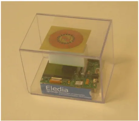
and a radial array of P electronically-reconfigurable passive elements (Fig. 1). The beamform-ing is carried out by actbeamform-ing on the electronically-driven RF switches controlled by the binary weights βp, p = 1, ..., P (i.e., βp = 1 when the p-th switch is on, βp = 0 otherwise). Thus,
the gain functionΓ of the antenna is adaptively tuned by setting a suitable configuration of the weight array β = {βp; p = 1, ..., P } (i.e., controlling the state of the parasitic elements).
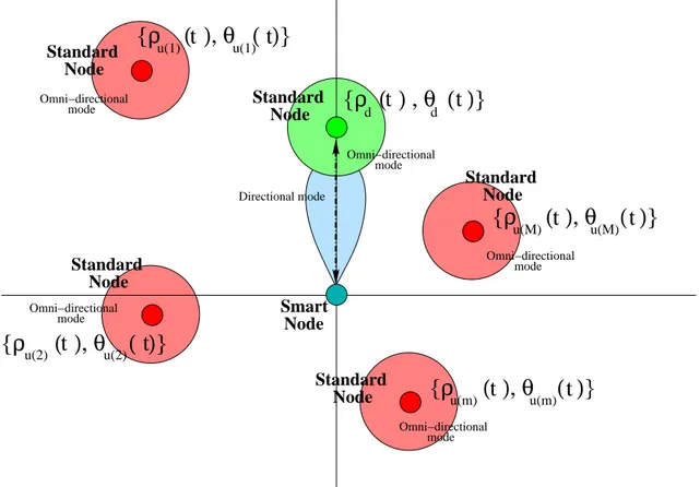
Let us now refer to a communication between a “desired” standard node and a “smart” device, which is working as the network gateway (master node), in the presence of M “undesired” standard nodes. With reference to Fig. 2, the node equipped with the smart antenna receives, at a generic time-instant t, the following signal
r(t) = gnθd(t) , β (t) ; t o d{ρd(t) , θd(t) ; t} + + M X m=1 gnθu(m)(t) , β (t) ; t o um n ρu(m)(t) , θu(m)(t) ; t o + n (t) (1)
where d denotes the signal transmitted at t by the desired node located at {ρd(t) , θd(t)},
um n
ρu(m)(t) , θu(m)(t) ; t o
is the m-th undesired signal, n is the unknown background noise, and gnθ, β(t) ; to=
r
Γnθ, β(t)o.
The total powerΦrreceived by the “smart” node is equal to
Φr(t) = Φd n θd(t), β (t) ; t o + M X m=1 Φu(m) n θu(m)(t) , β (t) ; to+ Φn(t) (2) where Φd n θd(t), β (t) ; t o = Γnθd(t), β (t) o [d {ρd(t) , θd(t) ; t}]2 (3) and Φu(m) n θu(m)(t) , β (t) ; to= Γnθu(m)(t) , β (t)o hum n ρu(m)(t) , θu(m)(t) ; t oi2 (4)
are measurable quantities.
In order to find the most suitable configuration of the antenna-beam at t, the optimal configura-tion of the weight coefficients βopt is determined by maximizing the SINR function of the link between the smart node and the desired one
SIN Rnβ(t) ; to= Φd n θd(t), β (t) ; t o PM −1 m=1 Φu(m) n θu(m)(t) , β (t) ; t o + Φn(t) . (5)
The direct maximization of (5) is not possible, since neitherΦu(m), m= 1, ..., M, is known nor
it can be easily measured at the receiver. Nonetheless, it can be demonstrated that the function
∆nβ(t) ; to= Ψd n θd(t), β (t) ; t o − Φn(t) PM −1 m=1 Ψu(m) n θu(m)(t) , β (t) ; to (6)
has a maximum for the same βoptas (5). In (6),Ψdis the signal strength (RSS) measured at the
receiver [11] according to the guidelines in [10] and given by
Ψd n θd(t), β (t) ; t o = Γnθd(t) , β (t) o [d {ρd(t) , θd(t) ; t} + n (t)]2. (7)
Moreover,Ψu(m)is the the m-th received interference strength (RIS) [11]
Ψu(m) n θd(t), β (t) ; t o = Γnθu(m)(t) , β (t)o hum n ρu(m)(t) , θu(m)(t) ; t o + n (t)i2. (8)
In order to maximize (6), the smart node tunes the binary weights βp, p= 1, ..., P according to
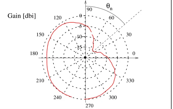
the PSO control logic described in [12][13]. More specifically, in order to reach the best condi-tion of the inter-node communicacondi-tion, the smart node dynamically determines the orientacondi-tion of the radiation pattern of the smart antenna. Towards this end, the actual value of∆ is measured and the more suitable among the P different orientations of the radiation pattern in Fig. 3 is chosen to obtain the lowest and the highest attenuation along the direction of the desired signal and of the interferers (i.e., towards undesired nodes), respectively.
By exploiting the reconfiguration capabilities of the smart antenna, two main issues of WSNs can be profitably addressed. For instance, the security level of the communication between the master node and the desired one can be enhanced by rejecting/attenuating the interfering signals coming from the (others) undesired nodes (Defence against Interferences). Moreover, the neighboring nodes of the master one can be localized and tracked (Sensor Node Positioning).
3
Experimental Analysis
In this section, the use of a smart node in a WSN architecture is discussed and the envisaged applications preliminary analyzed by considering a set of simplified, but illustrative, configura-tions.
3.1
“Defense against Interfering Signals” Scenario
Let us consider the case of a communication between a smart node (P = 18) with another
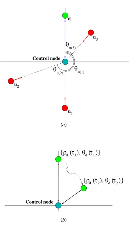
desired node in the presence of other active nodes acting as interferers for the communication link under test. With reference to Fig. 4(a), the control node is placed at the origin of the coordinate system, while the desired node is located at θd = 0o. The signals coming from
the undesired nodes (M = 3) impinge on the control node from the directions θu(1) = 180o,
θu(2) = 260o, and θu(3) = 40o, respectively. Both desired and undesired nodes operate at the
same frequency (i.e., co-channel interference) and radiate with the same intensity at different time-instants (τk, k = 1, ..., K; K = 3). As far as the experimental validation is concerned, the
following configurations have been considered: (1) u1(τ1) = d (τ1), u2(τ1) = u3(τ1) = 0; (2)
u1(τ2) = u3(τ2) = 0, u2(τ2) = d (τ2); (3) u1(τ3) = u2(τ3) = 0, u3(τ3) = d (τ3) [Fig. 4(a)].
Moreover, the measurements have been carried out in a non-controlled environment andΦnhas
been measured in the quiescent configuration [i.e., um(τ0) = d (τ0) = 0, m = 1, ..., M].
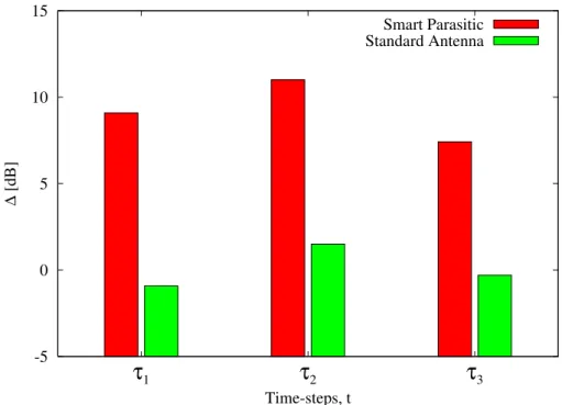
The obtained results are summarized in Fig. 5 where the behavior of the system, in terms of measured ∆ values, is described. For comparison purposes, the same result for a WSN equipped with a standard control node is reported. As expected, the smart architecture allows a non-negligible enhancement of the link quality with an improvement of about10 dB.
3.2
“Sensor Node Positioning” Scenario
The second scenario deals with the situation where the master node needs some information on the location of another moving sensor node to re-configure the management of wireless resources. Such a scenario is sketched in Fig. 4(b) where the moving node is located at [ρd(τk),
θd(τk)], k = 1, ..., K, with respect to the smart control node. At each time-step τk, k = 1, ..., K,
carried out by exploiting the flexibility of the smart antenna and according to the following procedure:
• the smart node determines the antenna setting [i.e., the optimal configuration β(τk)] that
allows the reception of the maximum level of signal from the slave node. Since both the transmitted power and the gain function of the omnidirectional antenna of the slave node are known quantities, the distanceρˆd between the two nodes is determined according to
the Friis’ relationship [14]. Moreover, the control node also stores the angular position of the maximum of its own radiation pattern to give an estimate of the angular location
ˆ θ′
d(τk) of the moving node;
• in order to improve the estimation of θd(τk), the smart node tunes the orientation of the
reference pattern (Fig. 3) around ˆθ′
d(τk) by looking for the position of the null θn(τk)
that minimizes the level of the signal received by the slave node.
In order to assess the feasibility and reliability of such a solution, the experimental validation has been performed by considering a set of K = 5 time-steps. The results are reported in Tab. I in terms of the location errors defined as
εθ(τk) = θˆd(τk) − θd(τk) θd(τk) × 100 (angular error) (9) and ερ(τk) = |ˆρd(τk) − ρd(τk)| ρd(τk) × 100 (distance error). (10)
As it can be noticed, despite the presence of a background noise, the angular coordinate of the slave node has been carefully estimated [εθ(τk) ≤ 12 - Tab. I], while greater errors verify in
the distance estimation [ερ(τk) ≤ 35].
4
Conclusions
In this paper, some advantages and potentialities of the integration of smart antennas in a WSN architecture have been envisaged and preliminary assessed by means of a set of experiments dealing with test configurations. Although concerned with simplified scenarios, the obtained
results confirm the feasibility and relevance of such an integration. Let us consider the “WSN topology control” (Sect. 3.2), it is certainly of great importance and suitability when monitoring dynamical scenarios (e.g., landslips or avalanches). As a matter of fact, the free-of-charge (i.e., without the use of a position sensor) detection of the location of each node of the network might be profitably employed in automatic alert systems for civil protection.
Besides these positive effects, the integration of “intelligence” at the physical layer of the net-work architecture allows one the development/improvement of a large number of other func-tionalities currently of high interest in both WSN researches and, in general, wireless networks. As a matter of fact, some trivial benefits coming from such an integration turn out to be: (a) an efficient spatial management of the radiated energy for RF energy-saving purposes as well as to improve the network coverage and connectivity; (b) an efficient and adaptive (e.g., based on the environmental conditions) reuse of wireless links to significantly increase the network throughput and solve coexistence problems coming from the integration with other wireless standards/technologies (i.e., RFID or UWB).
On the other hand, it should be pointed out that, some improvements in both flexibility and impact of the adaptive antenna on the WSN node are needed to properly address the most de-manding requirements arising in large scale and realistic applications. As an example, let us consider the presence of fully-adaptive antennas (instead of switched beam devices). It would strongly improve the efficiency of each node as well as of the whole network architecture when dealing with the detection and suppression of intentional network attacks devoted to alter or/and destroy data links. Because of a wider number of degrees of freedom (compared to that of a switched-beam system) in adapting the radiation pattern to the electromagnetic environment, there would be the possibility of synthesizing a radiation pattern with the main lobe directed towards the direction of arrival of the signal of interest and with nulls along the interference directions. Unfortunately, up till now, complexity, size, and energy consumption prevent their current implementation in WSN. Future researches will be aimed at properly addressing such an issue.
References
[1] R. H. Roy, “An overview of smart antenna technology and its application on wireless communication systems,” Proc. IEEE Conf. Personal Wireless Comm., pp. 234-238, 1997.
[2] S. Bellofiore, C. A. Balanis, J. Foutz, and A. S. Spanias, “Smart-antenna systems for mobile communication networks. Part 1: Overview and antenna design,” IEEE Antennas Propagat. Mag., vol. 44, no. 3, pp. 145-154, Jun. 2002.
[3] A. Kalis and T. Dimitriou, “Fast routing in wireless sensor networks using directional transmissions,” International Journal Mobile Network Design and Innovation, vol. 1, no. 1, pp. 63-69, 2005.
[4] S. Bellofiore, J. Foutz, C. A. Balanis, and A. S. Spanias, “Smart-antenna systems for mobile communication networks. Part 2: Beamforming and network throughput,” IEEE Antennas Propagat. Mag., vol. 44, no. 4, pp. 106-114, Aug. 2002.
[5] H. Singh and S. Singh, “A MAC protocol based on adaptive beamforming for ad hoc networks,” Proc. IEEE Int. Symp. Personal, Indoor and Mobile Radio Comm., pp. 1346-1350, 2003.
[6] S. Bellofiore, J. Foutz, R. Govindarajula, I. Bahceci, C. A. Balanis, A. S. Spanias, J. M. Capone, T. M. Duman, “Smart antenna system analysis, integration and performance for mobile ad-hoc network (MANETs),” IEEE Trans. Antennas Propagat., vol. 50, no. 5, pag. 571-581, May 2002.
[7] C. Yang, S. Bagchi, W. J. Chappell, “Location tracking with directional antennas in wire-less sensor networks,” Proc. IEEE MTT-S Int. Microwave Symp., pp. 131-134, 2005.
[8] D. Leang and A. Kalis, “Smart Sensor DVBs: sensor network development boards with smart antennas,” Proc. IEEE Conf. Comm., Circuits and Systems, pp.1476-1480, 2004.
[9] M. Donelli, R. Azaro, L. Fimognari, and A. Massa, “A planar electronically reconfigurable Wi-Fi band antenna based on a parasitic structure,” IEEE Antennas Wireless Propagat. Lett., vol. 6, pp. 623-626, 2007.
[11] D. Son, B. Krishnamachari, and J. Heidemann, “Experimental study of concurrent trans-mission in wireless sensor networks,” Proc. 4th Int. Conf. Embedded Networked Sensor Systems, pp. 237-250, 2006.
[12] M. Donelli, R. Azaro, F. De Natale, and A. Massa, “An innovative computational approach based on a particle swarm strategy for adaptive phased-arrays control,” IEEE Trans. An-tennas Propagat., vol. 54, no. 3, pp.888-898, Mar. 2006.
[13] M. Benedetti, R. Azaro, D. Franceschini, and A. Massa, “PSO-based real-time control of planar uniform circular arrays,” IEEE Antenna Wireless Propagat. Lett., vol. 5, pp. 545-548, 2006.
[14] G. Franceschetti, Electromagnetics - Theory, Techniques, and Engineering Paradigms. Plenum Press, New York, 1997.
Figure Captions
• Figure 1. Prototype of the smart node.
• Figure 2. Smart WSN architecture.
• Figure 3. Reference radiation pattern of the smart node [θn: angular null position].
• Figure 4. Geometry of the (a) “Defence against Interferences” Scenario and of the (b) “Sensor Node Positioning” Scenario.
• Figure 5. ”Defence against Interferences” Scenario - Behavior of ∆ in correspondence with different configurations.
Table Captions
Omni−directional mode Standard Node Omni−directional mode Standard Node Standard Node Node Smart Standard Node Omni−directional mode Standard Node Omni−directional mode Omni−directional mode Directional mode
t t
{ρ ( ) , θ ( )}
d dt t
u(1) u(1) u(2) u(2)t t
{ρ ( ), θ ( )}
{ρ ( ), θ ( )}
u(m) u(m){ρ ( ), θ ( )}
t t
{ρ ( ), θ ( )}
u(M) u(M)t t
0 -5 -10 -15 90 60 30 0 330 300 270 240 210 180 150 120
Gain [dbi]
θ
nu3 u1 u1 u2
θ
u(1)θ
u(2)θ
u(3) Control node d (a) dρ τ
1{ ( ), θ ( )}
dτ
1 dρ τ
2{ ( ), θ ( )}
dτ
2 Control node (b)-5 0 5 10 15