POLITECNICO DI MILANO
Corso di Laurea Specialistica in Ingegneria Informatica Dipartimento di Elettronica, Informazione e Bioingegneria
AN ARCHITECTURE FOR FUNCTION POINTERS
AND NON-INLINED FUNCTION CALL IN
HIGH LEVEL SYNTHESIS
Relatore: Prof. Fabrizio Ferrandi Tesi di Laurea di: Marco Minutoli, matr. 736023
C O N T E N T S a b s t r a c t xiii 1 i n t r o d u c t i o n 1 1.1 Premise 1 1.2 The problem 2 1.3 Proposed solutions 2 1.4 Results 3
1.5 Structure of the thesis 3 2 s tat e o f t h e a r t 5
2.1 Introduction to High Level Synthesis 5 2.2 PandA and High Level Synthesis 7
2.2.1 Frontend analysis 7 2.2.2 Resource allocation 7 2.2.3 Scheduling 8 2.2.4 Module binding 8 2.2.5 Register binding 8 2.2.6 Interconnection 8 2.2.7 Memory architecture 8 2.3 High Level Synthesis tools 9
2.3.1 Bambu 10 2.3.2 Legup 10 2.3.3 Vivado HLS 11 2.4 Target architecture 12 2.5 Synthesis of pointers 13 2.6 Function calls 14 3 m e t h o d o l o g i e s 17 3.1 Methodology introduction 17 3.2 Accelerator Interface 18
3.3 Wrapping accelerators 19 3.4 Function Call Mechanism 20
3.4.1 Notification mechanism 22
3.4.2 Simulation of the call mechanism 23 3.5 Function Pointers 24
3.6 Testing Environment 26 4 w i s h b o n e w r a p p e r 27
4.1 Minimal interface 27
4.1.1 Inputs and Output of the accelerator 29 4.1.2 Master chain signals 29
4.1.3 Slave chain signals 30 4.2 Wishbone 4 protocol basics 31
4.2.1 The interface 32
4.2.2 The wishbone classic bus cycle 33 4.2.3 The standard single write cycle 34 4.2.4 The standard single read cycle 35 4.3 WB4 wrapper circuit 35
4.3.1 The wishbone interface controller 36 4.3.2 The interconnection logic 36
5 f u n c t i o n c a l l s a n d f u n c t i o n p o i n t e r s 41 5.1 Architectural overview 41
5.1.1 The wishbone interconnection 42 5.2 Non-inlined function calls 43
5.3 Source code transformation 44 5.4 Front-end analysis 47
5.5 Architecture generation 48
5.5.1 The new memory allocation policy 49 6 p o r k s o c 51
6.1 Motivation 51
6.2 Architecture requirements 52 6.3 PorkSoC base architecture 53
6.4 Extending the architecture with accelerators 55 6.5 Experiments 55
6.6 Synthesis Results 57 7 d i s c u s s i o n 59
7.1 Study case 59
7.2 Synthesis of the study case 60 7.3 Results 61
8 c o n c l u s i o n 65
8.1 Final considerations 65 8.2 Future developments 66
Contents
b i b l i o g r a p h y 67 a c r o n y m s 71
L I S T O F F I G U R E S
Figure 2.1 High Level Synthesis (HLS) flow 5
Figure 3.1 Block diagram of the proposed architecture 18 Figure 3.2 Memory mapped interface of function sum 19 Figure 3.3 Synthesis of inlined call mechanism 21
Figure 3.4 Sequence diagram of the notification mechanism 23 Figure 4.1 Block diagram of the minimal interface 28
Figure 4.2 Wishbone entities interconnected 31 Figure 4.3 Wishbone handshake protocol 34 Figure 4.4 Wishbone standard write cycle 34 Figure 4.5 Wishbone standard read cycle 35
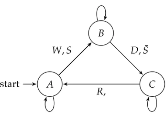
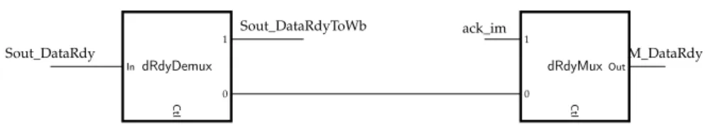
Figure 4.6 Wishbone interface controller state machine 36 Figure 4.7 Wrapper logic for the DataRdy signal 37
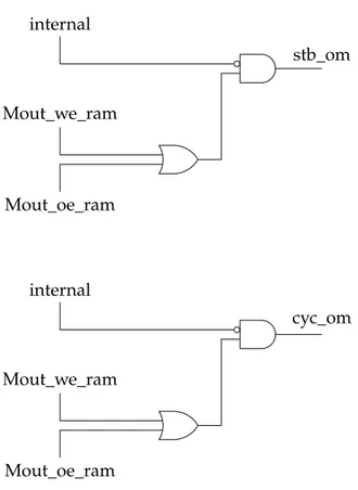
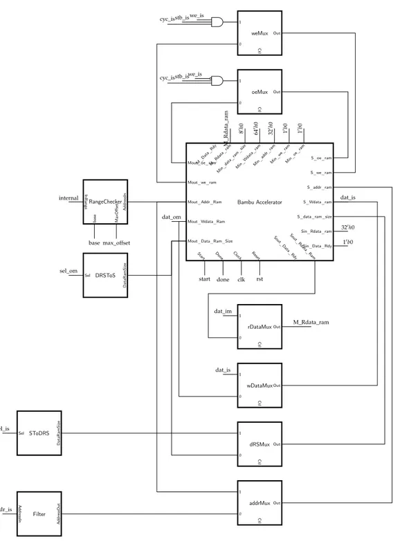
Figure 4.8 Wrapper logic for stb_om and cyc_om signals 38 Figure 4.9 Wishbone 4 wrapper logic 39
Figure 5.1 Block diagram of the implemented architecture 41 Figure 5.2 Block diagram of the wishbone interconnection 42 Figure 5.3 Builtin state machine of a function that takes a parameter
and has a return value 46
Figure 5.4 Call graph before and after transformation 47 Figure 5.5 Call graph before and after front-end analysis 48 Figure 5.6 notify_callerstate machine. 49
Figure 5.7 Call graph example for the allocation policy 50 Figure 6.1 PorkSoC base architecture 54
L I S T O F TA B L E S
Table 6.1 Synthesis report for PorkSoC + crc32 on the DE1 57 Table 7.1 Synthesis report of architecture with wishbone interface on
Altera Cyclone II EP2C70F896C6 62
Table 7.2 Synthesis report of architecture with non-inlined call on Altera Cyclone II EP2C70F896C6 62
Table 7.3 Number of clock cycle of function execution measured from simulation. Numbers for __builtin_wait_call and Doolit-tle_LU_Solve are measures from the first call. Case of inter-nal I. 63
L I S T I N G S
3.1 Example behavioral description . . . 19
3.2 Before transformation . . . 21
3.3 After transformation . . . 21
3.4 Pseudo code of the builtin function . . . 22
3.5 Function call using function pointer . . . 24
3.6 Transformed function call using function pointer . . . 25
4.1 Example of function with different input output interface . . . 28
5.1 Example of non-inlined calls . . . 43
5.2 Before transformation . . . 45
5.3 After transformation . . . 45
5.4 Function call using function pointer . . . 47
6.1 Test program for crc32 . . . 56
6.2 Call mechanism code . . . 57
A B S T R A C T
Modern embedded systems design increasingly couple hardware accelerators and processing units to obtain the right balance between energy efficiency and platform specialization. In this context High Level Synthesis (HLS) design flows can signifi-cantly reduce the effort needed to design these architectures. This thesis introduces a newHLSmethodology that supports the synthesis of tightly coupled clusters of accelerators suitable to be used as building blocks for architecture design with the introduction of PorkSoC, a templated System on Chip (SoC) suitable for automatic generation. The proposed methodology introduces the concept of non-inlined func-tion call and of funcfunc-tion pointers to the tradifunc-tionalHLSmethodology to synthesize cluster of accelerators able to call other accelerators to perform their computation without the mediation of a General Purpose Processor (GPP).
1
I N T R O D U C T I O N
This chapter is an introduction to the work done. It starts with a brief premise on the motivation of this thesis. Then it continue describing the problem addressed and giving a brief description of the proposed solutions. Finally it presents briefly the results obtained. Last section of the chapter overviews the structure of the thesis.
1.1 p r e m i s e
Modern embedded system design is increasingly exploiting architecture hetero-geneity to build faster and more power efficient systems. High-end products like smartphones and tablets typically include in their architecture hardware accelera-tors. The design of this kind of systems is generally complex. The design process, testing and validation of these architectures require big efforts from designers.
The adoption of High Level Synthesis (HLS) design flows can help to lower the complexity and the cost of the design of such architectures. For this reason, the current generation ofHLStools is constantly gaining market shares supported by the appealing features of recent tools.
Recently third party companies, such as Berkeley Design Technology Inc. (BDTI) [BTD], have started offering tool certification programs for the evaluation ofHLS tools in terms of quality of results and usability. For example, BDTI has evalu-ated the usability and the quality of results offered by AutoPilot in synthesizing accelerators for Digital Signal Processing (DSP) applications. The comparison has been made against mainstreamDSPprocessors. Results have show that accelerators synthesized by theHLStool have 40X better performance of theDSP implementa-tion. Moreover, the Field Programmable Gate Array (FPGA) resources utilization
obtained with theHLS tool are comparable with hand-written Register Transfer Level (RTL) designs.
In this context, this thesis extend the currentHLSmethodologies proposing an architecture supporting the synthesis of accelerators using a new non-inlined call mechanism, the introduction of function pointers and a System on Chip (SoC) designed to be generated inside a hybridHLSflow.
1.2 t h e p r o b l e m
The usual approach inHLSis to translate each function in a module implementing the corresponding Finite State Machine with datapath (FSMD) [GR94]. When the FSMDreach a function call, it transfer the control to an instance of the corresponding module and wait for the computed result. This approach implies that a distinct module instance is needed for each called function inside the data-path of its caller. In some sense this approach is similar to function inlining in compilers. The advantage of this approach is that each function call has no cost in terms of performance at the expense of duplication and therefore area consumption.
This implementation strategy has another non negligible drawback. In this model a function is seen as mere computational object that taking input values from input ports produces a results on the output port. This approach does not allow to associate addresses to the synthesized function and this makes impossible to implement language features like function pointers and everything that relies on it. This work proposes a methodology that improves the usual implemented model defining addresses for function and implementing a new call mechanics that support this model and improves resource sharing trading some clock cycles.
1.3 p r o p o s e d s o l u t i o n s
The proposed methodology takes inspiration from the design pattern of memory mapped peripherals widely adopted in the computer architecture world. This architectural solution consists of a set memory mapped registers used to configure the behavior of the unit, to pass inputs and retrieve outputs. This architectural pattern carries the advantages of clearly defining the interface between software and hardware layers without imposing complexities on the programming model.
The implemented solution translates function inputs and the return value as memory mapped register plus a control register used to start the computation. This strategy is not followed globally but only applied to marked function in the behavioral description leaving freedom to designers to easily explore different solutions. As a final step the generated accelerators are connected through a shared bus that can be easily connected to a more complex architecture.
1.4 results
This methodology has been implemented inside Bambu which is theHLStool of the PandA framework 1
. All the generated accelerators and the final architec-ture are Wishbone B4 (WB4) [Ope10] compliant which is a widely adopted bus communication protocol inside the open hardware community.
Integration in a more complex architecture has been tested inside PorkSoC. PorkSoC is a minimalistic SoC, based on the OpenRisc Or1k processor, that has been developed during this work.
1.4 r e s u lt s
The evaluation of the performance obtained with the architecture defined by the proposed methodology has been performed using the study case ofchapter 7. In the considered study case, results show that the proposed methodology allows to obtain area savings of around the 15% of the logic elements contained in the targetedFPGAover the design synthesized using the traditional methodology. The area savings obtained come at the cost of the overhead of the non-inlined function call mechanism introduced by the proposed methodology. The overhead of the non-inlined call mechanism can be divided in two components. The first component is due to the new parameter passing mechanism and it is proportional to the number of the function parameters to be transferred. The second constant component is due to the introduced notification mechanism. The final result is that the propose methodology trades off the introduction of the overhead of the non-inlined call mechanism to obtain a smaller architecture. This approach can make the difference synthesizing big accelerators with complex call graphs. In these cases the difference can be between faster designs that does not fit in the targetedFPGAand slower one that does fit in it.
A more detailed discussion of the results obtained can be found inchapter 7.
1.5 s t r u c t u r e o f t h e t h e s i s
Following chapters describe in more details the proposed methodology and give a detailed overview of the implemented solutions.
chapter 2contains a presentation of the current state of the art.
chapter 3 presents the proposed methodology and gives insights about the motivation of the step followed during the design of the presented solution.
chapter 4 describe the design of the bus interface built around accelerators synthesized by the PandA framework.
chapter 5goes into the detail of the implementation of non-inlined function call and function pointers.
chapter 6presents PorkSoC, theSoCthat has has been designed for automatic generation. PorkSoc has also served as testing environment for the integration of the synthesized accelerators inside more complex architectures.
chapter 7presents simulation and synthesis results.
chapter 8concludes the thesis with final discussion on the obtained results and gives an overview of the possible future developments.
2
S TAT E O F T H E A R T
This chapter starts giving an introduction to HLS. Then it continues giving an overview of the tools implementing HLSflows. Finally, it presents the state of the art of the target architecture and pointer synthesis.
2.1 i n t r o d u c t i o n t o h i g h l e v e l s y n t h e s i s
HLSinvestigates techniques and methodologies that translate algorithmic descrip-tions given in a high level language to a hardware micro-architecture description implementing the input algorithm. In a typicalHLSflow, the source language is a restricted dialect of a high level programming language (e.g. C/C++ Mathlab) used to capture the behavioral description of the design. The output of the flow will be in a Hardware Description Language (HDL) (e.g. Verilog, VHDL) capturing theRTL description of the resulting micro-architecture.
Front-end Optimizer Allocation
Scheduling Binding Code Generator source IR HDL Figure 2.1:HLSflow
The architecture of aHLStool follows the usual organization of a compiler tool. The first component of the chain is the front-end. Front-ends in compiler technology have the responsibility of performing lexical and syntactical analysis. The output produced by the front-end is an intermediate representation (IR) used as as input language by the compiler optimizer. The optimizer performs program analysis and transformation on theIRwith the aim of producing a semantically equivalent but improvedIR. In this context all code optimization algorithm known from compiler literature can be used. After the optimizer there is theHLSback-end.
The back-end contains several steps that transforms the optimizedIRinto anRTL representation. This representation is enriched with detailed implementation infor-mation needed for the generation of aFSMDin a hardware description language. The process of generating theFSMDincludes several steps but of the whole process three can be considered critical: allocation, scheduling and binding.
Allocation selects functional units to be used to performs the operation contained into theIR. Usually synthesis tools have a library of components to choose from. The library usually contains multiple modules that can perform an operation of the IRwith different area and timing. The allocation process is generally constrained by some performance goal of the design.
Scheduling maps each operation of the IR to the clock cycle when it will be executed. InHLSthis is called control step. It is important to notice that more than one operation can be mapped to the same control step as far as data dependencies are met. This can be a challenging task especially when memory operation are involved. Another constraint that has to be taken into account is the resource availability determined during the allocation step.
Binding maps operation to a functional unit and values computed to storage resources. The mapping is computed with the objective of minimizing the number of needed hardware resources trying to share them whenever possible.
It is important to note that those three steps are dependent to each other. A consequence of this tight relation is that an optimal solution of one of those step can lead to a sub-optimal one of the others. This is known as the phase ordering problem. The last block of the tool chain is the code generator. This will produce the Verilog or VHDL source to be synthesized. As said it is usually in aFSMDform that is obtained by the previous step. The datapath is obtained by the allocation and binding decisions. The controller is obtained by the scheduling and binding decisions.
This concludes the brief description of theHLSflow. A more deep and detailed discussion of problem and solution can be found in [WCC09].
2.2 panda and high level synthesis
2.2 pa n d a a n d h i g h l e v e l s y n t h e s i s
PandA is a framework developed as research project at Politecnico di Milano. Its primary goal is to provide an environment to experiment with new ideas and methodologies in the hardware-software co-design field.
The PandA framework hosts a set of tools, named after wild beasts and vegetation, each covering a piece of the proposed work-flow. Following this convention the tool implementingHLSis named Bambu.
Bambu receives as input a behavioral description of an algorithm expressed in the C language and generates a Verilog1
RTL description as output. The HDL description follows best-practices forFPGAdesign and is vendor independent. This design choice has permitted to easily integrate back-ends forRTL synthesis tools for Altera, Lattice and XilinxFPGAs.
Bambu implements theHLSflow as described in the overview ofsection 2.1. The following subsections give a more detailed description of how the flow has been implemented inside Bambu.
2.2.1 Frontend analysis
Bambu relies on the GNU Compiler Collection (GCC) for the early stages in the compiler pipeline. The source language is parsed and translated in a Static Single Assignment (SSA)IRcalled GIMPLE. GIMPLE is theIRused byGCCto perform optimization in the compiler middle-end. The result of the middle-end optimization insideGCCis fed as input to the front-end of Bambu for additional analysis and transformation passes specific to the HLS flow. For example the tool computes in this stage Control Flow Graph (CFG), Data Flow Graph (DFG) and Program Dependency Graph (PDG) that will be used in following stages to extract parallelism from the sequential description.
2.2.2 Resource allocation
The resource allocation step maps operation contained in the IR to Functional Units (FUs) contained in the resource library. The mapping is done taking into account type and size of operands. The library can contain multiple FUs with different timing and area usage that can be allocated for a given operation. In this case the tool takes a decision based on the constraints and objectives given by the designer.
1 Bambu generates also functional units in VHDL when floating point operations are involved. The
2.2.3 Scheduling
The objective of this step is to build a scheduling of the operation that satisfy the given constraints (e.g. timing constraints and resource availability). The scheduling algorithm implemented inside the tool is a priority list-based one. In priority list-based algorithms, operations have priorities used to decide the scheduling. The algorithm proceeds iteratively mapping each operation to a control step of the final FSMD.
2.2.4 Module binding
The module binding step associates physical FUs to operations. The objective of this step is to maximize resource sharing among operations taking into account that concurrent operations need differentFUs. Bambu solve this problem reducing it to a weighted graph coloring problem. In the implemented formulation weights represent the convenience of sharing the sameFUfor two given operations. Weights are computed taking into account timing and area characteristics of eachFU.
2.2.5 Register binding
This step associates a physical register to each storage value contained in IR op-erations starting from the information given by the Liveness Analysis. Again the problem is reduced to a graph coloring problem on the conflict graph representing liveness overlapping between SSA temporaries. Must be noticed that the same problem is solved inside the back-end of a software compiler with the additional constraint that the number of available registers is bounded by the number of registers of the target architecture. HLSdoes not have this constraint because tools can add additional registers to the architecture when necessary.
2.2.6 Interconnection
This step starts from the work done by previous steps and builds the logic needed to interconnect resources. It introduces all the required logic to implement resource sharing and it binds control signals that will be set by the controller.
2.2.7 Memory architecture
The step of memory allocation takes care of where each variable is allocated. With respect to each function a variable can be allocated internally to the data-path or externally. Internally allocated memories are accessed directly through the
2.3 high level synthesis tools
data-path while externally allocated memories are accessed through a memory interface.
The memory interface is composed of two chains, one for masters and one for slaves. The chain is closed by a global external interface that determines if the address accessed is internal or external to the core. A more detailed description of the memory architecture can be found in [PFS11].
2.3 h i g h l e v e l s y n t h e s i s t o o l s
One of the most important feature of the current generation of HLS tools is the adoption of C-like (i.e. C, C++ and SystemC) specification as input of the synthesis flow. The introduction of support of C-like specification has contributed to increase theHLSuser base. In fact, a C based specification language extends the range of potential user to designers more familiar with programming languages than with HDLs. It also facilitates complex tasks like HW/SW codesign, HW/SW partitioning and design space exploration. It allows to use compiler technologies to performs design optimization. For this reason several HLSflows have been implemented on top of compiler tools (i.e. Bambu, LegUp and AutoPilot).
Another important key aspect that has influenced positively the evolution and adoption ofHLS flow is the rise ofFPGAdevices. In the last years,FPGAs have improved in capacitance, speed and power efficiency. For this reason many HLS tools have been designed specifically targeting FPGAs, i.e. LegUp [Can+11], GAUT [CM08], ROCCC [Guo+08], SPARK [Gup+04] and Trident [TGP07] [Tri+05].
The past generations ofHLStools have failed to gain significant market shares despite the interest of the industries and research communities. A good survey of the history and the reasons of the failures of HLS technology of the past can be found in [MS09] and [CCF03].
The current generation of HLS is instead increasingly gaining success in the industry world mostly because the current generation has:
• better support of the C based input language • better quality of results
• motivated the adoption of the new design methodologies in the industry world with its better results and usability.
Most widespreadHLS tools include AutoESL’s AutoPilot (after its acquisition from Xilinx is known as Vivado HLS), Cadence’s C-to-Silicon Compiler [Cad08], Forte’s Cynthesizer [CM08], Mentor’s Catapult C [Bol08], NEC’s Cyber Work-bench [CM08], and Synopsys Synphony C [Syn] (formerly, Synfora’s PICO Express, originated from a long-range research effort in HP Labs [Kat+02]).
2.3.1 Bambu
The current generationHLStools accept as input a dialect of the C/C++ language that include only a subset of the language features. For example common restrictions are on the usage of pointers and some commercial tool requires that every pointer must be statically resolved at compile time. Bambu tries to not impose such restriction on the designer by generating architectures capable of dealing with language construct that other tools simply consider illegal. In this spirit this work add the last missing feature to cover the whole C language: function pointers.
Another language feature relevant to this work is the concept of function and its translation to hardware modules. TheHLS flow, as implemented inside Bambu, translates each function in a module that takes function parameters as input and eventually produces one output at the end of the computation. The computation inside the function module is implemented by the means of aFSMD. Function calls are translated instantiating the called function module inside the data-path of the caller. When a function is called multiple times inside the body of a function it is possible to share the instantiated function module in order to save area. If the same function is called inside the body of another function an additional instance of the callee is needed and it will be included into the data-path of the caller. This mechanism is similar to function inlining in software compilers with the difference that the inlined function can be shared inside a hardware module, if called multiple times. This is what can be considered as the state-of-the-art approach to function calls translations and it is the strategy used by every tool.
2.3.2 Legup
LegUp [Can+11] is an open source HLS tool being developed at University of Toronto. As stated on the homepage of the project2
its long-term goal is to make FPGAprogramming easier for software developer. Moreover this project is tradi-tionally used by PandA as a term of comparison.
LegUp is similar to Bambu in terms of functionality and proposed methodology. The first notable difference between the two tools is that LegUp uses the LLVM infrastructure to build theHLSflow. But this is not the only difference.
At the architectural level the distinguishing difference is the memory architecture. While both tools have the concept of local memory and external memory, they differ radically in the architecture and decoding mechanism. Particularly the key difference is that LegUp reserves the higher bit of the address to store a tag that is uniquely bound to each memory allocated into the architecture.
Another notable difference between the two tools is that LegUp offers what they call hybrid flow. The hybrid flow synthesize an architecture that contains a TigerMIPS
2.3 high level synthesis tools
processor with a set of accelerators built from marked functions and offers to designers an easy way to test HW/SW partitioning. The PandA framework does not implements currently an equivalent of the Legup hybrid flow.
A noticeable missing feature of the tool is the lack of support for floating point operations.
2.3.3 Vivado HLS
One of the tools that can be considered state-of-the-art in the industry world is Vivado HLS by Xilinx. This section presents some information of the HLS methodology extracted from the documentation of the product.
Xilinx has released a short manual [Xil13] with the goal of introducingFPGA design with their HLS synthesis tool, Vivado HLS, to software engineers. The document explains general concepts of hardware design and covers feature and limitation of the implementedHLSflow. Unfortunately, it does not give any insight of the implementation details.
Two of the concepts presented inside the document are of interest to our discus-sion: functions and pointers.
The description given about function is quite vague but it is clear that inside the framework their treatment is similar to the one implemented for loops. It is clearly stated that for each function it is created an independent hardware module. Those modules can be instantiated multiple times and can execute in parallel.
It also presents the memory allocation policy of the tool warning the reader that any dynamic allocation mechanism is not supported. Moreover, it explains that pointers can be used for two types of memory access: internal and external.
Pointers declared inside the body of a function are permitted when pointing internally allocated objects. Constraints are sightly different when the pointer is declared in a function parameter. In fact, any pointer access on function parameters must imply an internal allocated object or an external memory that will be accessed through an external bus protocol such as the Advanced eXtensible Interface (AXI). Moreover, the tool imposes that any pointer accessing internal objects must be statically resolvable at compile time. The following quote from [Xil13] clarifies the previous statement of what is considered to be legal by Vivado HLS in terms of pointers to internally allocated objects.
The HLS compiler supports pointer usage that can be completely an-alyzed at compile time. An analyzable pointer usage is a usage that can be fully expressed and computed in a pen and paper computation without the need for runtime information.
2.4 ta r g e t a r c h i t e c t u r e
Modern systems design is increasingly moving to heterogeneous architecture to exploit the performance and the energy efficiency of such systems. The design of such large systems has exposed the limitations of traditional system architectures favoring the emergence of new architectural solutions. For example, architecture composed with hundreds of simple cores connected together have exposed scalabil-ity issue in the interconnection of such a number of cores. In order to address this problem, many architecture have defined tightly coupled clusters of accelerators and used them as building blocks [Mel+12] [Bur+13] [Plu] [Cor].
There are essentially two different approaches in defining the interaction between accelerators included in this kind of architecture. The first makes use of a shared memory communication mechanism. The second approach makes use of specialized instructions specifically defined to communicate with hardware accelerators.
An example of the first solution is presented in [Bur+13] and [Bur+12]. In these two works the authors defines the architecture of an heterogeneous shared memory clusters and its OpenMP based programming model. The defined clusters includes General Purpose Processors (GPPs) and hardware accelerators and a shared memory. Inside the cluster, the connection between accelerators and the cluster interconnect is mediated by the Data Pump module. This modules multiplexes data accesses to/from the accelerators. It has been introduced to allow to include a great number of accelerators without increasing the complexity of the interconnection. The communication betweenGPPs and hardware accelerators is performed by means of memory mapped registers. Other works have approached the scalability issue with the introduction of hardware modules hiding the increasing latency between the shared memories and the processing units. The work of Burgio et al. defines an architectural solution that is similar to the one proposed in this thesis. The two key difference between the proposed architecture and the one defined in [Bur+13] are the absence an equivalent of the Data Pump and the possibility to synthesize clusters that do not includeGPPs.
An example of the second approach is the Molen architecture [Vas+04] [PBV07]. In this two works the authors define the architecture of the Molen machine and its programming paradigm. The works of Vassiliadis et al. and Panainte, Bertels, and Vassiliadis are in the context of Reconfigurable Computing (RC). Their works start analyzing the common issue of theRCprogramming models. Then they define a set of specialized instruction to reconfigure the programmable logic included into the design and to communicate with loaded accelerators. In particular parameter passing and result retrieval is performed by means of two specialized instructions that moves data between theGPPregister file and the XREGs File. The XREGs File is a set dedicated register for input and output of hardware accelerators. Even in this case theGPPand the reconfigurable unit have access to a shared memory. The
2.5 synthesis of pointers
design proposed with the Molen architecture overcome some of the limitation of the previous works using the same approach. For example, their works does not suffers of the op-code space explosion because they do not use a different specialized instruction for each accelerator that can be configured in the programmable logic included inside the design. Another important improvement is that their proposed solution does not have any limitation on the number of input and output that accelerators can have.
Both the Molen architecture and the template architecture defined in [Bur+13] include mechanism to perform accelerator call with the cooperation of aGPP. As it will be exposed in chapter 3, this thesis overcome this limitation building a mechanism that allows accelerators to make use of other accelerators to perform their computation without the need of aGPP.
2.5 s y n t h e s i s o f p o i n t e r s
The semantic of pointers, as defined by the C language, represents the address of data in memory. This definition starts from the assumption that the target architec-ture consists of a single contiguous memory space containing all the application data. Unfortunately this assumption is not valid in HLS and the treatment of pointers have required special attentions from designers. In fact, in hardware data may be stored in registers, memories or even wires.
Moreover, pointers can be used to read and write the data they point to but also to allocate and de-allocate memory dynamically.
The synthesis of pointers and their optimization has been analyzed in [SSDM01] and [SDM01]. These two works defines the foundations of the synthesis and optimization of pointers in the current HLSmethodologies.
[SSDM01] analyzes the operations that can be performed through pointers in the C programming language and propose strategies for their synthesis. The three operation taken into account by this work are loads, stores and dynamic memory allocation and de-allocation.
For the treatment of loads and stores the authors distinguish between two situa-tions: pointers to a single location and pointers to multiple locations. Pointers to a single location can be removed replacing loads and stores operation with equivalent assignment operation to the pointed object. In the case of pointers to multiple locations, load and store operations are replaced by a set of assignments in which the location is dynamically accessed according to the pointer value. Addresses (pointer values) are encoded using two fields: a tag and an index. The tag is used to recognize the memory storing the accessed data. The index is used as offset to retrieve the data from the memory. With this strategy, loads and stores can be removed using temporary variables and branching instructions. [SDM01]
defines analysis and transformations that can be performed in order to optimize the synthesis of loads and stores operation through pointers.
The dynamically memory allocation and de-allocation is addressed using both hardware and software memory allocators. [SSDM01] concentrates on the hardware solution giving hints on a possible software strategy. The proposed solution makes use of a hardware module implementing the malloc and free operation. The proposed module is able to allocate storage on multiple memories in parallel. As a consequence of this design choice the dynamically allocated space is partitioned into memory segments.
[SSDM01] and [SDM01] does not take into account the synthesis of function point-ers. The reason behind this missing is that traditionallyHLS considers functions as computational units taking inputs and producing outputs that do not have a location in memory.
This thesis extends on these works proposing a methodology that includes accelerators in a memory mapped architecture and defines mechanisms to use function pointers for accelerator invocation.
2.6 f u n c t i o n c a l l s
The are two traditional synthesis methods to performs function calls: inlining as performed by a software compiler and the inlining as performedHLStools.
The inlining method used by software compilers replaces function call with the body of the called functions. In HLS, it has the advantage of keeping the datapath small because it exposes more resource sharing opportunities during the synthesis. In fact, performing the inlining of all the functions of a design gives the possibility to share resources between functions boundaries. The inlining has also the advantage of removing any kind of performance degradation caused by module communication. Unfortunately, the inlining approach increases the area and the delay of the controller due to the explosion of its number of states.
The inlining method used byHLStools instead produces a different module for each function contained in the design. The synthesized modules are then included inside the datapath of its callers. This approach as the advantage of synthesizing smaller function modules. This is reflected in the size the function module controller that is smaller and faster than in the previous case. In the rest of this thesis this is the approach referenced as inlined call mechanism.
[Har+06] starts from this premises and defines a mechanism of function merging to be associated to the inlining mechanism ofHLStools. Function merging allows the synthesized module to increase the resource sharing inside the synthesized module without incurring in the drawback of the inlining mechanism. The work of Hara et al. proposes an Integer Linear Programming (ILP) formulation to decide the merging strategy.
2.6 function calls
The work of Hara et al. proposes a solution to increase resource sharing at fine grain level. The methodology proposed in this thesis instead proposes a coarse grain approach that can be supported by the methodology proposed in [Har+06].
3
M E T H O D O L O G I E S
This chapter presents the methodology followed during the design and the imple-mentation of the proposed solutions. It starts giving an overview of the overall methodology. Then it defines all the concepts introduced by methodology.
3.1 m e t h o d o l o g y i n t r o d u c t i o n
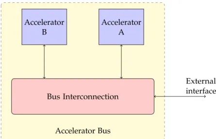
The purpose of the methodology proposed by this thesis is to introduce the concept of non-inlined function calls and function pointers to the framework of HLS. As introduced insection 1.2,HLStools translate functions toFSMD. With the current methodologies, function calls are translated instantiating the module implementing the called function into the data-path of the caller. The implication of this method-ology is that the module of a function is instantiated into the data-path of its callers. This approach limits the resource sharing of function modules to the possibility of multiple calls from the same caller. This thesis proposes a new methodology that extends the current approach with the possibility of inter-procedural sharing of function modules. The final result of the new methodology will be an architecture interconnected through a bus. The accelerators composing the architecture will be able to call other accelerators using the mechanism defined by the methodol-ogy. Figure 3.1 shows a block diagram of the final architecture containing two accelerators.
In order to obtain the desired result, this thesis defines a suitable interface for the accelerators, a call mechanism and a notification mechanism. The definition of this concepts suggests the introduction of function pointers and their architectural meaning in the context ofHLS. The following sections introduce the newly defined entities and mechanisms.
Bus Interconnection Accelerator A Accelerator B Accelerator Bus External interface
Figure 3.1: Block diagram of the proposed architecture
3.2 a c c e l e r at o r i n t e r fa c e
The first entity that must be defined is the accelerator interface. It is the fundamental building block underpinning other concepts defined by the introduced methodology. Its definition must fulfill two requirements. First, the defined interface must enable to easily plug synthesized accelerator in bigger modular design. Second, it must ensures ease of use from hardware and software components. These characteristics will enable to integrate the proposed methodology in more complex hardware/software co-design flows.
The architectural solution proposed for the accelerator interface definition is the usage of memory mapped registers. This is a well established architectural design pattern in the industry world. It is used for example in computers to access the video card and other peripherals. The pattern is extremely simple. The interface exposes a pool of registers that are mapped into the address space of the architecture. The exposed registers can be of three kind: input, output and control registers. Input and output register are used to pass and retrieve data through the interface. Control registers are used to set operating modes.
Following the pattern just described, the proposed interfaces includes a set of input registers, an output register and a control register. The set of input registers stores input values necessary to the accelerator. The output register stores the return value of the computation performed by the accelerator. The control register allows to start the computation and to monitor its state.
To better explain the proposed solution lets look at how the behavioral description ofListing 3.1translates to the memory mapped interface of an accelerator.
3.3 wrapping accelerators
Sum control register Input a Input b Output register Accelerator
base address
Figure 3.2: Memory mapped interface of function sum
int sum(int a, int b)
{
return a + b; }
Listing 3.1: Example behavioral description
The behavioral description of the accelerator sum in Listing 3.1 gives all the needed information to define its interface. The function sum takes as input two integer values and produces as output another integer value. This information translates in a memory mapped interface that contains four registers. The first register is the control register. Its address will be associated to the function. It will be the first thing allocated inside the address space of the accelerator. The second and third registers are used to store the two inputs of the function. The last one is return value. It will store the result at the end of the computation. Input and output registers are optional because functions may not need inputs and may not have return values.
TraditionallyHLStools translates function input and output as module ports. In this case the interface may be implemented as a wrapper around the synthesized accelerators. The same strategy has been adopted to integrate the methodology into the PandA framework.
3.3 w r a p p i n g a c c e l e r at o r s
One of the most important design choice of the PandA framework is to be vendor agnostic in all its part. This choice was made in order to avoid problems that can arise by product discontinuity. For this reason, and in the spirit of supporting the open-hardware community, the implemented solution makes use of the WB4bus protocol instead of other available proprietary alternatives.
TheWB4protocol can be considered the de facto standard for what concern com-munication protocols inside the open-hardware community. TheWB4specification has been developed and is currently maintained at OpenCores [Ope10].
The standard flow implemented in Bambu translates function to accelerators with a minimal interface. This interface contains a set of ports for inputs and for return
value, a set of control signal (i.e. clock, reset and start) and, when needed, a set of ports used for memory operations.
The current memory architecture is based on the work described in [PFS11] as detailed insection 4.1.
The bus interface and the communication protocol defined by the minimal interface for memory operations and by the WB4specification are very similar. For this reason the accelerator WB4 interface has been implemented as a wrapper layer around the minimal interface accelerator. The wrapper logic can be decomposed in three elements: a set of registers, a controller and the interconnection logic. The set of register is used to implement the memory mapped interface described in section 3.2. The controller is a state machine activated by the control register used to start and notify the end of the computation. Wrapped accelerators may need to access the external bus or may need to connect with the internal slave chain during the computation. The interconnection logic takes care of discriminating bus access types and dynamically build the needed connection to complete the communication.
3.4 f u n c t i o n c a l l m e c h a n i s m
Once defined the accelerator interface, it can be defined the call mechanism using the memory mapped interface of the accelerator. The first operation that the caller must perform is passing parameters to the accelerators. In a memory mapped architecture, this step is performed by a series of write operation to the addresses of the accelerator input registers. After that, the caller can start the computation. The command that start the computation is a write operation to the control register. The caller has two options at this stage. It can write zero or a notification address inside the control register. The meaning of the notification address will be explained in subsection 3.4.1while introducing the notification mechanism.
Following the analogy of the software function call, the described mechanism is equivalent to fill the activation record of a function and then jump to the address of its first instruction.
When an accelerator completes the computation, the caller get notified by a change in the state of the control register and, if activated, by the notification mechanism. The notification mechanism can be deactivated in order to implement different hardware-software interaction models (i.e. interrupt driven). The default hardware behavior always activate the notification mechanism.
At this point the caller can read the return value from the callee interface and continue its computation.
Figure 3.3shows the inlined function call mechanism and its architectural equiva-lent. HLSflows tools traditionally synthesize functions as modules having input ports for function parameters and an output port for the return value. The call is
3.4 function call mechanism
int funA(int a, int b)
{
// ... }
int funB{int a, int b)
{ // ... funA(a, b); // ... } (a) code funA funBdata-path Inputs Output Start (b) architecture
Figure 3.3: Synthesis of inlined call mechanism
performed asserting the start signal of the called functionFSMDand keeping its input stable until the computation is complete. Using this methodology, the module of the caller function contains an instance of the module of the called accelerator.
In order to distinguish between the inlined and the non-inlined function call mechanism, the methodology defines the hwcall attribute. The hwcall attribute is used to mark the functions that are synthesized as top accelerators and that use the non-inlined function call mechanism. Calls to marked function are translated using a builtin function hiding the implementation details of the call mechanism. Listing 3.2andListing 3.3show the transformation performed on the call to function sum.
__attribute__((hwcall))
int sum(int a, int b)
{
return a + b; }
int funA(int a, int b, int c)
{
int e;
e = sum(a, b); return c * e; }
Listing 3.2: Before transformation
__attribute__((hwcall))
int sum(int a, int b) { ... }
void
__builtin_wait_call(void *, ...);
int funA(int a, int b, int c)
{ int e; __builtin_wait_call( sum, 1, a, b, &e); return c * e; }
Listing 3.3: After transformation
The __builtin_wait_call function is a var-arg function. The first argument is the address of the accelerator to be invoked. The second argument is a Boolean flag that used to distinguish if the return value of the called function must be stored or not. Subsequent arguments are the input to pass to the called function. When
void __builtin_wait_call(void * fun, ...) { sendParameters(fun); startComputation(fun, CALL_SITE_ADDRESS); waitNotification(); if (was_rhs_of_assignment()) { readReturnValue(); writeReturnValue(); } return; }
Listing 3.4: Pseudo code of the builtin function
the second parameter is one, the last argument passed to the builtin function is the address of the variable where the return value must be stored at the end of the computation.
Listing 3.4shows in a C-like pseudo code macro operation that an hardware imple-mentation of the __builtin_wait_call performs. The instantiated Intellectual Property (IP) performing the hardware call will start passing all the input parame-ters to the called accelerator using the architecture bus (sendParameparame-ters(fun)). Then it starts the computation writing in the control register of the called accelerator the notification address associated with the call site of the replaced function call (startComputation(fun, CALL_SITE_ADDRESS)). The call site address is an address allocated for the instruction calling the __builtin_wait_call. Its value is defined during the memory allocation step. After that, theIPwaits the notification message declaring the end of the computation (waitNotification()). If the orig-inal function was in the right-hand side of an assignment (was_rhs_of_assignment()), the __builtin_wait_call will read the return value (readReturnValue())
from the called accelerator and it stores its value to the left-hand side (writeResultValue).
3.4.1 Notification mechanism
The introduction of non-inlined function calls carries with it the definition of a notification mechanism for computation completion.
The interface definition ofsection 3.2specifies that the information of the status of the accelerator is exposed through the control register. Using this information, a simple notification mechanism could be to let the caller periodically check the control register of the callee. Unfortunately this strategy does not scale with the number of hardware callable accelerators. In fact, the periodical check of callers can congest the bus. Moreover due to bus congestion, called accelerators may be unable
3.4 function call mechanism
to perform memory operations needed to complete the computation. In the end, the polling strategy can lead to deadlocks.
The proposed methodology solves this problem with the introduction of notifi-cation addresses. Performing the hardware call, the caller can ask to be notified by the callee when the computation is done. At the end of its computation, the callee will notify the caller performing a write operation to the notification address provided during the non-inlined function call. The notification address is associated during the memory allocation step with the call site of the function. Giving different address to each call site helps to distinguish between calls to the same function that are performed in the same caller. The allocation of the notification address does not impose the allocation of a memory or a memory mapped register.
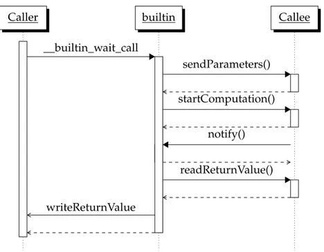
3.4.2 Simulation of the call mechanism
Caller builtin Callee
__builtin_wait_call sendParameters() startComputation() notify() readReturnValue() writeReturnValue
Figure 3.4: Sequence diagram of the notification mechanism
The diagram in Figure 3.4shows the complete sequence of events happening during a non-inlined function call. When the control flow of the caller reach the call site of the original function call, it starts the execution of theIPimplementing the __builtin_wait_call. TheIP start writing parameters to the registers of the called accelerator. Then, it starts the computation of the callee writing the notification address into the callee control register. The notification address used is the address associated with the call site of builtin call. When the callee completes
void sort(char * vector, size_t n,
int (*compare)(int a, int b))
{ // ... for (...) { if (compare(vector[i], vector[i-1])) { // ... } } // ... }
int less(int a, int b){ return a < b; }
int greater(int a, int b){ return a > b; }
int f(int a)
{
char vec[] = { ’b’, ’c’, ’a’ };
if (a)
sort(vec, 3, less); else
sort(vec, 3, greater); }
Listing 3.5: Function call using function pointer
its work, it send the notification message performing a write operation at the notification address stored in the control register. The builtin module then retrieve the return value and write it to the variable used by the caller to store the return value of the original call. This last step is performed only when the original call was a right-hand-side of an assignment. After that, the builtin module return the control to the caller.
3.5 f u n c t i o n p o i n t e r s
The presented methodology supports function pointers. In the context of the proposed architecture, a function pointer is the first address of the memory mapped interface of the accelerator. As described during interface definition, the first address of the memory mapped interface corresponds to the address of the control register. According to the proposed methodology, function calls through function pointers can be performed using the defined call mechanism.
Listing 3.5shows an example using function pointers. The function sort use a function pointer to call a compare function passed as parameter. This call is translated injecting the __builtin_wait_call described insection 3.4. In this
3.5 function pointers
void sort(char * vector, size_t n,
int (*compare)(int a, int b))
{
// ...
for (...)
{
__builtin_wait_call(
compare, 1, vector[i], vector[i-1], &tmp);
if (tmp) { // ... } } // ... }
int less(int a, int b){ return a < b; }
int greater(int a, int b){ return a > b; }
int f(int a)
{
char vec[] = { ’b’, ’c’, ’a’ };
if (a)
sort(vec, 3, less); else
sort(vec, 3, greater); }
case the, its first parameter will be the compare function pointer. Listing 3.6 show the result of the transformation of the call through compare. The difference between this case and the previous one is that the value of the compare function pointer is passed at run-time. Its value will determine the accelerator invoked inside the architecture.
3.6 t e s t i n g e n v i r o n m e n t
Mechanism defined in the proposed methodology have been tested using PorkSoC as a playground. PorkSoC is a System on Chip designed to be automatically generated. The long term goal is to include it in a hybrid HLSflow. A detailed discussion of its design can be found inchapter 6.
PorkSoC has been used also to test the accelerator integration inside a more complex designs. As part of the testing, we had the opportunity to verify the interaction between accelerators and software executed by the processor included in PorkSoC.
4
W I S H B O N E W R A P P E R
This chapter gives a detailed description of the design and implementation of the WB4wrapper that the proposed methodology builds around accelerators synthe-sized by Bambu. The chapter starts giving a description of the minimal interface and the protocol used by its memory interface. Then it continues presenting the WB4interface and the communication protocol. The chapter ends describing the details of the implementation of the wrapper circuit.
4.1 m i n i m a l i n t e r fa c e
In the PandA framework the minimal interface is the interface obtained following the standard synthesis flow of hardware accelerators. It has been designed to be extremely simple in order to obtain maximum performance from the synthesis flow. The architecture of the accelerators is organized in two daisy chains. One for masters components and one for slaves components. The two chains are used to perform internal and external memory operation. During external memory operation, master and slave chains of an accelerator have direct access to the minimal interface and, through it, to the outside world. During internal memory operation the two chains are closed on each others to build the communication channel.
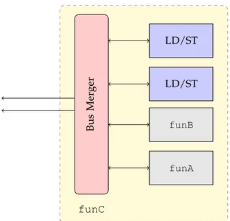
Figure 4.1 shows a block diagram of the architecture. The accelerator funC contains two functional units used to perform memory operation (LD/ST) and two functional units to compute function funA and funB. The bus merger has the task to forward requests from internal module through the exposed interface.
The minimal interface of synthesized accelerators is dynamically generated. The generation starts from the signature of the synthesized function and from the information of the memory allocation. Its interface signals can be organized in four
Bus Mer ger LD/ST LD/ST funA funB funC
Figure 4.1: Block diagram of the minimal interface
int funA(int a, int b) {}
void funB(int a, int b) {}
void funC(){}
Listing 4.1: Example of function with different input output interface
sets: control signals, accelerator inputs and output, master chain signals and slave chain signals.
Of the four sets, only the set of control signals is always included in the interface. The set of control signals contains four elements: clock, reset, start_port, done_port. The clock and reset have the usual meaning. The other two control signals allows to start (start_port) and get notified (done_port) when the computation is done.
The other three sets are optional and they are included when needed by the syn-thesized accelerator. Their inclusion and their content depends from the signature of the function being synthesized and from the decision taken during the memory allocation step of the synthesis flow. Their meaning and their inclusion policy will be explained in the following subsections.
4.1 minimal interface
4.1.1 Inputs and Output of the accelerator
The first optional part of the minimal interface is the set of module ports that represents inputs and the output of the synthesized function. Listing 4.1shows all the possible cases that can happen.
The first case is represented by the function funA. This function represents all the functions that take any given number of arguments and produce a return value. In this case the accelerator with the minimal interface will have one input port for each parameter and one output port, named return_port, that will contain the return value.
The opposite case is represented by the function funC. In this case the function does not need any inputs and does not produce any output. The minimal interface of the synthesized accelerator will reflect this characteristic. As a consequence, the generated minimal interface for the accelerator will not have any ports for inputs and output.
The last case represented by funB lays in between the two preceding. In this case the function has a list of inputs but does not have a return value. This will be reflected into the minimal interface including an input port for each function parameter but omitting the return_port.
4.1.2 Master chain signals
Master chain signals are the portion of the interface that is used to start memory operations. Their inclusion in the interface is conditioned by the kind of operation included in the synthesized function and by the decision taken during memory allocation. The need or not of these signals depends on where the memory allocation step has allocated memories that the synthesized accelerator accesses during the computation. Essentially there are two cases that make this interface needed. The first case is that the synthesized function need to access memory located higher in the hierarchy. The other case is that the accelerator may access memories outside the boundaries of the accelerator.
Master chain signals can be organized in two distinct sets. The first is composed of the following signals:
m o u t_data_ram_size Size of the data to be read or written by the master initiating the bus cycle. The size is transmitted as the number of bit to be read or written. m o u t_wdata_ram The data to be written. This is meaningful only during a write
cycle.
m o u t_addr_ram The address of the data to be read or written. m o u t_we_ram Asserted during write cycles otherwise set to zero.
m o u t_oe_ram Asserted during read cycles otherwise set to zero.
For each of the previous signals exist an equivalent input signal used to build the master chain. A master making a request will use these output signals to start a bus cycle.
The other set is the return channel of the communication. It contains the in-formation coming back from the addressed slave. It contains the following two signals:
m_data_rdy Acknowledge signal for the master waiting the completion of the requested read or write operation.
m_rdata_ram Data read from the selected address. Contains a meaningful value only at the end of a reading cycle.
4.1.3 Slave chain signals
Like the master chain signals, even the slave chain signals are included by the minimal interface generation step on a need basis. Again the inclusion or not depends on the decisions taken during the memory allocation step of the synthesis. They will be included when the synthesized accelerator contains memories that must be accessible through the architecture bus.
Slave chain signals can be organized in distinct sets. The first set is used to propagate the request coming from the master chain inside the slave chain. It includes the following signals:
s_data_ram_size Size of the data involved in the operation. The size is transmitted as the number of bit to be read or written.
s_wdata_ram The input data to be written in the destination address. s_addr_ram The destination address for the current operation.
s_we_ram Input to be asserted to perform write operation otherwise set to zero. s_oe_ram Input to be asserted to perform read operation otherwise set to zero.
The other set is used to send back the response to the master chain. It includes the following two signals:
s o u t_data_rdy Acknowledge signal for the master waiting the completion of the requested read or write operation.
s o u t_rdata_ram Data read from the selected address. Contains a meaningful value only at the end of a reading cycle.
4.2 wishbone 4 protocol basics
Wishbone
Master Intercon
Wishbone Slave
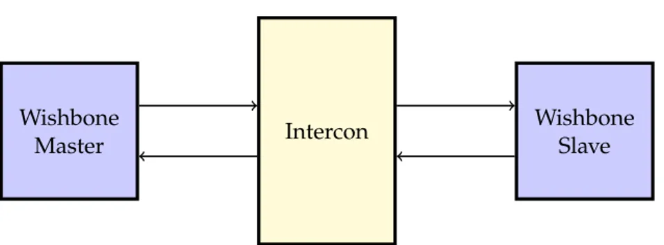
Figure 4.2: Wishbone entities interconnected
4.2 w i s h b o n e 4 p r o t o c o l b a s i c s
This section presents the features of theWB4protocol used by the implementation of the wishbone wrapper. The interested reader can find the complete specification of the interface and its bus cycles inside the wishbone specification [Ope10].
The wishbone specification is very general. Its generality lays on the absence of architectural constraints imposed by the specification other than a precise definition of the interfaces and the communication protocol.
The specification defines the three entities that are involved during the commu-nication: the wishbone master, the intercon and the wishbone slave. Wishbone masters and slaves are object implementing the wishbone master and slave interface respectively. The intercon is a wishbone module that interconnects master and slave interfaces. Figure 4.2gives a schematic view of the interconnection in a wishbone bus.
The specification does not prescribe any particular topology for the interconnec-tion or any specific interconnecinterconnec-tion mechanism. The choice is left to the architecture designer but any possible interconnection mechanism is compliant with the spec-ification. Inside the specification document there are outlined a few possible architectural solution for the implementation of the intercon including: point-to-point connection between wishbone masters and slaves, crossbar and a shared bus.
The specification precisely defines the communication protocols between wish-bone masters and slaves defining bus cycles. According to the definition given by the specification, a bus cycles is the process whereby digital signals affect the transfer of data across a bus by means of an interlocked sequence of control signals. The specification defines two bus cycles: the wishbone classic bus cycle and the wishbone registered feedback bus cycle. Moreover, the wishbone classic bus cycle has two possible variants: the standard bus cycle and the pipelined bus cycle.
The wishbone specification does not impose to support every variant of the communication protocol. In order to be compliant with the specification, it is enough to support only the wishbone bus cycle chosen by the designer.
The following subsections describe the wishbone interface as implemented by the wrapper logic built around Bambu synthesized accelerators and the classic bus cycle in the standard version.
4.2.1 The interface
The wishbone specification defines a rich interface in order to support all the defined bus cycles. An interface is not required to implement all of them to be compliant with the specification. But at the same time the specification defines the minimal set of signals that master and slave interface must have to implement the communication protocol. The wrapper wishbone has been designed to use the wishbone classic bus cycle. Its interface exposes only the minimal set of signals necessary to implement the communication protocol.
The following subsection give the definition of the used signals following the organization of theWB4specification. The specification organizes the signal de-scription in three groups: signal common to master and slave, master signal and slave signal. The description will follow the same organization and the same name convention of the wishbone specification.
Signals common to master and slave
c l k_i The clock input coordinates the activity of internal logic with the interconnect. According to the specification all output signals must be registered with the clock and all the input must be stable before the rising edge.
r s t_i The reset input force the interface to restart. At the same time all the internal state machines must be set to their initial state.
d at_i The data input is used to transfer binary data. d at_o The data output is used to transfer binary data. Master signals
a c k_i The acknowledge input. Its assertion indicates the normal termination of a bus cycle.
a d r_o The address output is used to pass addresses.
c y c_o The cycle output. Its assertion gives the start to the communication. The cycle output must be asserted during whole bus cycle.
4.2 wishbone 4 protocol basics
s e l_o The select output indicates where valid data is expected on dat_i during a read operation or where valid data is put on dat_o during a write operation. Its size is determined by the granularity of the port.
s t b_o The strobe output identifies a valid data transfer. This signal has an impor-tant role in more complex bus cycles. In our discussion it will be asserted always when cyc_o is.
w e_o The write enable output identifies read and write operation. This signal is asserted during write operations and negated on read operations.
Slave signals
a c k_o The acknowledge output. The slave interface assert this signal to indicate the normal termination of a bus cycle.
a d r_i The address input is used to pass addresses.
c y c_i The cycle input indicates that a valid bus cycle is in progress.
s e l_i The select input indicates where valid data is expected on dat_o during a read operation or where valid data is put on dat_i during a write operation. Its size is determined by the granularity of the port.
s t b_i The strobe input when asserted indicates that the slave is selected. Slaves must respond to other wishbone signal only when this is asserted.
w e_i The write enable input identifies read and write operation. This signal is asserted during write operations and negated read operations.
4.2.2 The wishbone classic bus cycle
The wishbone classic bus cycle is the simplest communication method described inside the specification document. According to the specification, every wishbone bus cycle is initiated by the master interface asserting the cyc_o signal. When the cyc_osignal is not asserted all other master signal must be considered invalid. On the other side, slave interfaces respond to slave signals only when the cyc_i is asserted.
All the bus cycles define a handshaking protocol between master and slave interfaces. The timing diagram inFigure 4.3shows the handshaking protocol for the standard version of the wishbone classic bus cycle with a synchronous slave from the master perspective. As shown in Figure 4.3 the master interface assert the stb_o signal when it is ready to transfer data to the slave. The stb_o signal will remain asserted until the slave interface assert the ack_i signal to terminate
clock cyc_o stb_o ack_i
Figure 4.3: Wishbone handshake protocol
the bus cycle. On the rising edge of the ack_i signal, the master interface will de-assert the stb_o signal. This gives control over the data transfer rate to both master and slave interfaces.
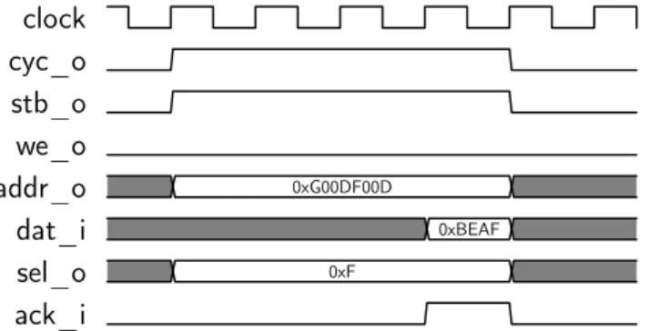
The following two subsection presents the standard single write cycle and the standard single read cycle.
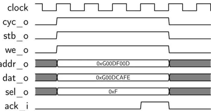
4.2.3 The standard single write cycle
clock cyc_o stb_o we_o addr_o 0xG00DF00D dat_o 0xG00DCAFE sel_o 0xF ack_i
Figure 4.4: Wishbone standard write cycle
The timing diagram inFigure 4.4shows a standard single write cycle from the master interface perspective. The bus cycle works as follow.
When a master is ready to perform a write operation it set to a valid address the adr_o signal and to the appropriate value the dat_o and sel_o signals. Concurrently it assert the we_o, cyc_o and stb_o signals. After that the master start monitoring the ack_i signal waiting for the slave response.
The selected slave will decode the inputs and register value of the dat_o signal. As soon as the operation is completed the slave asserts the ack_i signal to notify the master.
When the ack_i signal is asserted, the master de-asserts stb_o and cyc_o signals concluding the bus cycle.