Corso di Laurea Magistrale in Ingegneria
Meccanica
A methodological approach to re-engineer the
experience of consumer products based on the use of
haptic devices
Relatore:
Ing. Francesco FERRISE Correlatore:
Ing. Serena GRAZIOSI
Tesi di: Guilherme PHILLIPS FURTADO Matr. 764112
Corso di Laurea Magistrale
A methodological approach to re-engineer the experience of consumer products based on the use of haptic devices
by Guilherme PHILLIPS FURTADO Matr. 764112
Oggigiorno non esiste una maniera sistematica per catturare le preferenze tattili di un utente che interagisce con interfacce di prodotti di consumo quali cassetti, porte o pulsanti, n´e un metodo per tradurre tali preferenze in un meccanismo in grado di generarle. L’obiettivo del lavoro di tesi `e di proporre un metodo che permetta alle compagnie che operano nel settore dei prodotti di consumo di re-ingegnerizzare il feedback tattile di tali prodotti sulla base delle preferenze degli utenti. Questo metodo si basa sull’uso di prototipi virtuali interattivi con i quali l’utente pu`o interagire attraverso sistemi haptic a ritorno di forza. Tale ritorno di forza pu`o essere modificato in base alle preferenze dell’utente grazie ad un modello di forze che controlla l’interfaccia haptic, completamente parametrizzato. Questo permette di trasformare una serie di feedback percettivi puramente qualitativi in specifiche quantitative. Attraverso algoritmi di ottimizzazione queste specifiche quantitative sono successivamente tradotte in un meccanismo reale. La porta di una lavastoviglie `e stata utilizzata come caso di studio per dimostrare l’efficacia del metodo e identificarne i limiti.
keywords: haptics, tecnologia haptic, user experience design, virtual prototype, stima dei parametri
Corso di Laurea Magistrale
A methodological approach to re-engineer the experience of consumer products based on the use of haptic devices
by Guilherme PHILLIPS FURTADO Matr. 764112
Currently, there is no systematic way to evaluate users’ tactile preference when interacting with parts of consumer’ products such drawers, doors or buttons through the use of interactive virtual prototypes, nor a way to infer the spec-ifications of the mechanism that would be responsible for the desired haptic feed-back. The aim of this work is to describe a methodological approach that enables companies, operating in the consumer goods market, to re-engineer the haptic feedback from the interaction with such products according to users’ preferences, by creating an easily modifiable virtual prototype that is interacted with through a haptic interface. The haptic feedback provided by the virtual prototype is readily modified at the user’s request through the use of a parametric model that controls the haptic interface, responsible for transforming perceptual qualitative feedbacks into quantitative specifications. These quantitative specifications are transformed into the technical specifications of a real mechanism through the solution of an optimization problem. A dishwasher door has been used as case study in order demonstrate the effectiveness of the proposed methodology and to identify the limits.
keywords: haptics, haptic technology, user experience customization, virtual prototype, parameter estimation, mechanisms
Sommario i
Abstract ii
List of Figures v
List of Tables vii
1 Introduction 1
1.1 Technology Overview. . . 2
1.2 Related Works . . . 3
2 Methodological Approach 5 3 Physical System Modelling: Dishwasher Door 11 3.1 Simulation Software . . . 11
3.2 Description of the Dishwasher Door . . . 12
3.3 Dynamic model in AMESim . . . 14
3.3.1 Articulated mechanism . . . 14 3.3.1.1 Subsystem DOOR . . . 18 3.3.1.2 Subsystem PLATE . . . 18 3.3.1.3 Subsystem RELATIVESPEED . . . 20 3.3.1.4 Subsystem FRICTIONFORCE . . . 24 3.3.2 Latch mechanism . . . 25 3.4 Measurements. . . 27 4 Haptic rendering 34 4.1 Haptic Device . . . 34
4.2 Coding language and API . . . 36
4.2.1 H3D API . . . 37
4.2.2 Python . . . 37
4.2.3 X3D . . . 37
4.3 Haptic Model . . . 37
4.3.1 Transformation of Coordinates . . . 39
4.3.2 Constraining the end-effector . . . 41
4.3.2.1 First method: Radial direction stiffness . . . 41
Example: . . . 43
4.3.2.2 Second method: Restitution force based on dis-tance minimization . . . 43
4.3.3 Haptic Behavior Modelling . . . 49
4.3.3.1 Activation functions . . . 50
4.3.3.2 Unlocking Phase . . . 52
4.3.3.3 Locking phase . . . 53
4.3.3.4 Transition between locked and unlocked state. . . 54
4.3.3.5 Moving Phase . . . 54 4.4 Implementation . . . 57 Code Description . . . 59 X3D file . . . 59 Python file . . . 61 4.5 Experimental results . . . 63 5 Optimization 66 5.1 Designing the problem: Dynamic system parameter estimation . . 67
5.2 Solving the problem: Genetic Algorithm . . . 69
Chromosomes or Individuals . . . 69
Selection . . . 70
Recombination . . . 70
Mutation . . . 70
Methodology . . . 70
5.2.1 Parameter estimation of the system from measurements . . 71
5.2.2 Parameter estimation of the haptic model from measurements 72 5.2.3 From haptic model to technical specification. . . 74
5.2.4 Redesigning the dishwasher mechanism . . . 76
6 Conclusion 80
A Appendix A: X3D file for haptic rendering 82
B Appendix B: Python file for haptic rendering 89
2.1 Methodological Approach . . . 7
3.1 Description of components used from AMESim . . . 13
3.2 Mechanical components of the Door . . . 14
3.3 Sketch of the articulated mechanism . . . 16
3.4 Dry friction as an hyperbolic tangent . . . 17
3.5 Block diagram of the system. . . 17
3.6 Block diagram of the subsystem DOOR . . . 19
3.7 Block diagram of the subsystem PLATE . . . 20
3.8 Diagram of the plate . . . 21
3.9 Block diagram of the subsystem RELATIVESPEED . . . 23
3.10 Block diagram of the subsystem FRICTIONFORCE . . . 24
3.11 System representation of the latch mechanism . . . 25
3.12 Block diagram for the latch mechanism . . . 26
3.13 Force applied by the latch mechanism on AMESim model due to the spring . . . 27
3.14 Stiffness of the latch mechanism in function of position on AMESim model . . . 28
3.15 Sensor positioning for the measurements . . . 30
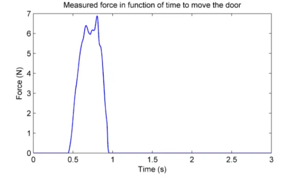
3.16 Measured force when unlocking the door in function of time . . . . 31
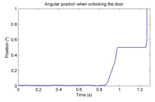
3.17 Measured position when unlocking the door in function of time . . 31
3.18 Measured force when locking the door in function of time . . . 32
3.19 Measured angular speed in function of time . . . 33
3.20 Measured input force in function of time . . . 33
4.1 Workspace of HapticMaster . . . 35
4.2 Model for the spring acting on the radial direction of a curve . . . 42
4.3 Elliptic trajectory theoretically followed by the end effector . . . . 44
4.4 Force applied by the user at the end effector for the elliptical tra-jectory . . . 44
4.5 Force magnitude necessary to maintain the end effector on the elliptic trajectory . . . 45
4.6 Circular trajectory followed by the system . . . 50
4.7 Magnitude of the force required to maintain the end effect on the circular trajectory . . . 51
4.8 Kinetic energy comparison. . . 51
4.9 Activation function . . . 52
4.10 Analysis of force required to unlock the door . . . 53
4.11 Asymmetry of dry friction . . . 56
4.12 Variable dry friction . . . 57
4.13 Velocity of the haptic model and the actual device - no friction . . 64
4.14 Force applied at the end effector - no friction . . . 65
5.1 Optimization model . . . 72
5.2 Comparison between the behavior of the system according on the estimated parameters. . . 73
5.3 Optimization model for the haptic behavior . . . 73
5.4 Haptic model in AMESim . . . 76
5.5 Comparison between the response of the system and haptic model (const. friction) . . . 77
5.6 Value of the coefficient A(θ) according to the position of the door. 79
5.7 Comparison between the response of the system and haptic model (var. friction) . . . 79
5.1 Genetic algorithm parameters . . . 74
5.2 Measured parameters. . . 74
5.3 Estimated parameters of the system . . . 75
5.4 Technical specifications obtained from the chosen haptic behavior . 78
There are numerous factors that influence the decision of people to purchase a product. It has been argued by researchers that what a prod-uct feels like can influence whether or not people will end up buying. For that reason, the people who are responsible for taking strategic decisions about new products, at the marketing division of companies, are urging de-sign teams to give priority to the dede-sign the user experience, later focusing at the functional and technical features. Touching a product, in particu-lar, plays an important role in our evaluation and appreciation of different products(Spence and Gallace [1]).
Currently, when designing the user experience of new products, com-panies may perform comparative tests involving potential customers as well as marketing experts, and taking as samples their own products or the products of competitors (Bhutta and Huq [2]). The result of these tests defines the expected behaviour of the new product, which becomes a sort of combination of the most appealing features of the tested products. Once the desired behaviour is defined, marketing experts must translate it into project targets, and then into design specifications with the help of research and development engineers. However, a methodological approach encom-passing all these steps is yet to be implemented, being one of the issues how to translate these design specifications, which are mainly qualitative, into quantitative specifications that would allow engineers to recreate the product envisioned by the marketing experts. Another issue that emerges from this process is that the initial phase of testing is based only on prod-ucts already available on the market, limiting the range of possible user experiences that could be tested by the experts [3].
1.1
Technology Overview
This work aims to address these issues on the process of designing the user experience by taking advantage of current virtual reality technologies that allow the interaction of users with virtual prototypes, focusing on the tactile experience. This way, it becomes possible for end users and marketing experts interact with the product on the initial phases of design, while allowing engineers to assert their preferences into quantitative parameters that govern the behaviour of the virtual prototype.
Virtual prototyping is a technique in the process of product de-velopment that involves mainly the use computer-aided design (CAD) and computer-aided engineering (CAE) software to simulate the behavior of the product in the real world, validating the design before committing to making a physical prototype. The flexibility offered by a virtual prototype allows designers to more quickly evaluate and explore different design alternatives, which can lead to improved quality and performance. They also allow the reduction of development costs and time required to bring the product to the market. It is possible for a person to physically interact with a virtual prototype by the use of virtual reality technologies.
Virtual reality is a term referring to computer-simulated environ-ments capable of simulating physical presence in places in the real world, as well as in imaginary worlds. To create a believable experience, virtual real-ity environments have to take advantage of our sensory capabilities, partic-ularly by rendering visual, auditory and tactile sensory information through the use of appropriate devices. Visual experiences are usually enabled by computer screens or stereoscopic displays, while auditory experiences can be created by sounds reproduced through speakers or headphones. Tactile information, also known as force feedback, can be generated through the use of haptic systems [4].
Haptic technology is a tactile feedback technology which takes advantage of the sense of touch by applying forces, vibrations, or motions to the user on a specified manner through the use of what is called haptic interface or haptic device. This mechanical stimulation can be used to assist in the creation of virtual objects in a computer simulation and to control
such virtual objects. It can be said the relation of haptic systems with the sense of touch is the equivalent of the relation between computer graphics and vision and of audio speakers and headphones to the hearing senses.
By exploiting haptic system capabilities of interacting with virtual prototypes, it is possible to facilitate the communication between collabo-rators of different disciplinary backgrounds when designing a new product, such as allowing engineers to quantify the physical sensations described by marketing experts and end-users. It also allow a greater range of experiences to be tested, as the characteristics of the virtual prototype do not need to be limited by the characteristics of existing products.
This project will focus on developing a method to design a tactile interactive virtual prototype, which behavior is defined by mathematical equations that correspond to the forces that the real product would exert when the user interacts with it, forces that can be changed in real time and are rendered through a haptic interface, later translated into real technical specifications of the mechanical system that would enable the desired be-havior to be reproduced into the real world. A dishwasher door is used as a case study, and the existing mechanism is re-designed to reproduce the specified behavior defined by marketing experts on the virtual prototype.
1.2
Related Works
Numerous studies have explored the interface between research and development teams and marketing teams and its role on the process of developing new products. Among many issues, difficulties in communication between these two tend to emerge due to difference on their working domains and their different models for the product representation [5, 6]. Another important issue is that customers’ requirements tend to be described into imprecise and non-technical terms [7].
The design of multisensory aspects of traditional consumer products is becoming a common practice in different product areas [1], such as food, cars and domestic appliances and can help marketing people understand
the demands of the customers, where the test of the perceptual feedback is usually based on the use of physical prototypes.
The use of physical prototypes is necessary when tests require the physical interaction with the product through the senses of touch and smell. With the technological advances in virtual reality, it is possible to simu-late both visual appearance and the sound emitted by products faithfully through the use of virtual prototypes. The use of virtual prototypes is gain-ing interest in industry, due to their flexibility and growgain-ing fidelity, aside from the advantages brought by reduction of development cost and time. Traditionally, most of the tests performed on Virtual Prototypes have been purely visual, aiming at evaluating the aesthetic aspects of a new product. More recently, a number of haptic devices have been developed to simulate the haptic feedback with products and their components. Shin et al. [8], for example, developed custom haptic devices to simulate the physical interac-tion with refrigerator, while Strolz et al. [9] developed them to simulate car doors. The aim of these haptic-based virtual prototypes is testing design solutions concerning the haptic behavior, and eventually review the design of the product.
In the works of Bordegoni and Ferrise [10][11] it has been demon-strated the effective use of a multisensory environment based on touch, hearing and vision to capture users’ preferences, already in the concept de-sign phase. These initial studies have demonstrated the potentiality of Vir-tual Prototyping in capturing users’ preferences, and have highlighted the necessity to change the way new products are designed[12]. Their use can improve the communication between marketing teams, engineering teams[3] and customers, and is focused on the present study.
In [12], the authors outline some advantages and requirements for an interactive virtual prototype to become the digital substitute of the physical prototype. The ones addressed on the present work are:
• It should be based on functional model for each technical domain – that is, the virtual prototype is a functional model that characterizes and simulates the domain (or the domains) of the real product to evaluate and test. In this work, the domain addressed is related to the force feedback the real product should give to the user. • Sharable among different stakeholders – an advantage of using virtual prototypes is that they can be shared over the network and accessed by different stakeholders at the same time.
• Modifiable and parametric – one of the most important advantages of Virtual Prototypes is that they can be easily modifiable and can be even parametric. By using the physical prototype of an object, an individual can generally only express an opinion as to whether he likes or dislikes it, but cannot easily test variants of the object. By using a parametric virtual model instead the user can ask to make changes of the prototype until he is satisfied.
• Real-time feedback – The interactive virtual prototype should react to user’s actions in real- time (from the user’s perception point of view). The simulation algorithms should be fast enough to grant a real-time feedback. If this is not feasible, simplified algorithms should be used. The simplifications should still give an adequate perception of the object. In that case, the problem moves from the simulation of the ideal physics- based behavior, to the simulation of the faithfully perceived physics- based behavior. In this work, we call such simplified model the ”haptic model”, and will be discussed in greater detail on
the appropriate section. It is highlighted that the most important aspect of the interactive Virtual Prototype is not the complexity of the simulation of the product, but how the results of the overall simulation is perceived by the humans.
• Sharable among different users located around the world – Sometimes testing activities on the same product must be performed in different cultural contexts or geographical regions. Interactive virtual prototypes enable such testing without shipping or reconstructing a physical prototype on these locations.
We describe the methodological approach that we believe enables a company to re-engineer the haptic feedback of a door (in this case a dish-washer door) on the basis of the optimization of the product experience, described on [13]. The method is schematically illustrated in Fig. 2.1. To this aim, virtual prototypes are adopted as means a user can adapt on the basis of his preferences until he gets his favourite experience. In this work, only the haptic feedback is adaptable, while the hearing and visual expe-riences are maintained fixed, thus the multisensory experience is created. The design of the multisensory product experience through interactive vir-tual prototypes has some open issues:
• How similar is the virtual prototype to the real product?
• How it can be made adaptable to user preferences and how it is pos-sible to correlate and easily translate those changes into new product specifications?
To address these issues, we identify two stages that come respectively before and after the testing of the multisensory product experience within a virtual environment:
• An initial stage, where a parametric virtual replica of the tactile feed-back of product in question is created and adjusted;
• A final stage to transform the desired behaviour of the virtual proto-type (obtained by implementing the changes requested by the user)
into the technical/physical specifications required to create the prod-uct in the real world.
Figure 2.1: The methodological approach described in this section [13]. The first stage starts with the analysis of the existing product (the dishwasher door) and its components or sub-systems (e.g. the door opening system) that affects the interaction. These components will be re-engineered in order to meet the perception desired by the user. A mathematical model of the door, with its sub-systems components, is derived, and its parameters will be related to the technical specifications necessary to build the system (the physical model). To create such a mathematical model, it is necessary to analyse the mechanism responsible for locking the door, and also the
hinge mechanism that controls the door position (e.g. links, spring and damping effects should be analysed). Therefore, the aim is to come out with the list of variables that control and determine the behaviour of the product. The resources necessary to perform this step can vary, depending on the amount of information already available.
The original behaviour of the door (”AS IS”) is characterized by
• The sounds that the door emits, in particular, the opening and closing sound, that can be recorded and reproduced by the interactive virtual prototype;
• Its visual appearance, that can be represented by a CAD model and displayed at a computer screen or a projector, for example;
• The force it applies to the user when interacting with it: the force required to unlock/lock and to move along its trajectory. These can be obtained through appropriate measures.
The last point can be addressed by creating another, simplified, mathematical model, whose behaviour is similar to the physical system, but it actually represents perceived physical behavior or the main charac-teristics of the door (haptic model), not its physical components, which is used to render the force feedback on a haptic interface. Such a step is fun-damental in order to come out with an easy-adaptable representation of the system behaviour on which is possible to carry out the simulation in real time in a way that becomes easy to change the behaviour of the virtual prototype.
While it is possible to make the haptic model exactly the same as the physical model, certain problems might emerge:
• If the equations of the physical system are too complex, it becomes difficult to know how each parameter translates into the final behavior of the door, so proper real-time evaluation and testing in a user-friendly manner might be compromised;
• If the physical system was modelled without using explicit equations, such as block diagram environments, it will either have to be rewrit-ten explicitly, or additional tools will have to be used or a computer program will have to be developed to allow interaction between this model and the haptic interface;
• The equations representing the physical system might be too complex to be rendered in real time on the haptic interface. The stiffness of the equations, or the necessity of solving them numerically might create unacceptable delays.
For these reasons, the haptic model on this study is a simplified ver-sion of the physical system that aims captures the main perceived sensations, defined by the parameters of the equations.
By measuring the force applied by the user to lock/unlock/move the door simultaneously with an appropriate state of the system, such the speed, acceleration and/or displacement, in function of time, we can say that the dynamical behavior of the original door is described. This behaviour is then used to adjust the parameters that govern the haptic model, in order for its behavior to become as close as possible to the one from original product. The adjustment is made through the use of an optimization algorithm that aims to minimize the difference between the output of the haptic model and the measured states, given the measured force as an input. The same procedure can be applied to tune the mathematical model of the physical system and find the original technical specifications.
The next step is to test the virtual prototype, where its visual ap-pearance, based on a CAD model, can be projected on a screen, and the haptic model is rendered by a haptic interface, allowing user to interact with the virtual prototype. The position of the end-effector of the haptic inter-face is synchronized with the displacement of the model of the door. Then, for example, the user can try to lock the virtual door and then request a smaller effort, or he can move the door and request to it to be more soft.
Once the desired behaviour has been identified, the final stage of the methodology can start. First, it is necessary to acquire the new (i.e. the “TO
BE”) behaviour of the door. This can be done by acquiring the behaviour of the haptic interface, which is measured internally with logs being generated, or registering the values of parameters governing the haptic model. While the most convenient way is to register the values of the parameters governing the haptic model, due to the lack of transparency of the haptic interface, it might not truly represent the perceived effort of the user. The process to obtain the technical specification consists on minimizing the difference between the haptic model response and the physical system model response, given the same input. This time, the parameters governing the physical model will be adjusted to minimize that difference through the use of a optimization algorithm.
Door
The system that will be used to evaluate the proposed methodology is the interaction with a dishwasher door. A mathematical model of the mechanism that controls the rotation of the door of dishwasher and the locking mechanism for closing is created, where the technical specifications (such as the value of the spring stiffness) are parameters of the mathematical model. Modelling the system enable us to estimate these parameters to accomplish a desired behavior.
3.1
Simulation Software
The dynamic system is developed and solved by the use of the sim-ulation software LMS-AMESim. AMESim is a commercial simsim-ulation soft-ware for the modelling and analysis of multi-domain systems. The softsoft-ware is a suite of tools used to model, analyze and predict the performance of mechatronics systems. Models are described using time-dependent ana-lytical equations that represent the system’s behaviour, which can be any combination of hydraulic, pneumatic, thermal, electric or mechanical sys-tems. To create a simulation model for a system, the set of standard libraries available from the commercial version is used, they contain pre-defined com-ponents for different physical domains. The icons in the system have to be connected and for this purpose each icon has ports, which have several inputs and outputs, according to the system they are representing[14]. The process for designing the system is similar to other simulation tools for modelling and analysing multidomain dynamic systems, such as the block diagrams of Scicos/Scilab. AMESim also comes with tools for ease use optimization algorithms such as genetic optimization and non-linear programming by
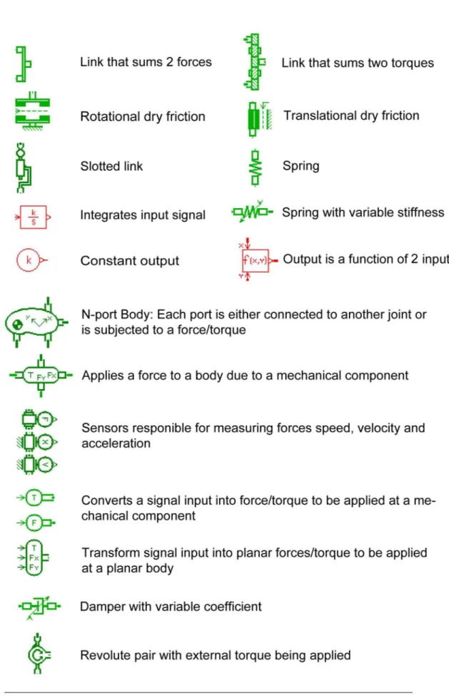
quadratic Lagrangian. The libraries used are Mechanical, Planar Mechani-cal and Signal, Control, and a brief description of the main component used for the model is given in Fig. 3.1.
3.2
Description of the Dishwasher Door
A dishwasher door provided by Indesit Company is used as the case study. The movement of the door is defined by a planar semi-circular trajec-tory, restricted to 90o. Depending on how the door and its opening mecha-nism have been designed, the force required to open it can vary. To open the door, typically, the user has to pull hard enough to unlock a spring-loaded mechanism. The latch mechanism used to lock the door, and specifically the component that clips into the locking mechanisms, is a plastic piece that can be represented as a leaf spring.
Once the door is no longer locked, a mechanism is responsible to maintain it stable, controlling the required force to move it. It consists of an articulated mechanism with a plate connecting all joints, a spring, three friction pieces, one rotating joint and one slotted link that allows vertical translation and rotation 3.2. All movements occur at the same plane.
The door is attached to the front side of the cabinet by means of a hinge placed at the bottom part of the door. The hinge provides an opportune balancing force, generated by the cumulative effects of the spring and of the frictions that interacts with the articulated mechanism, in order to guarantee the stability of the doors during its movement from the vertical to the horizontal position.
The plate has the purpose of transmitting a force, generated by the compression of the spring and the reaction of the frictions, on a desired manner, to the door, and also limiting its course to 90◦. It has 4 extremities, denoted as A, B, C and H. The extremity A is connected at the door through a rotating joint. Extremity B is connected to the cabinet by a slotted link, where friction is also present, affecting the vertical displacement of the joint. Extremity C is connected to the spring and another friction. The extremity H has the sole purpose of stopping the door when it is fully open, by colliding
Figure 3.1: A brief description of the components used to develop the model of the dishwasher door.
Figure 3.2: Mechanical components responsible for controlling the door’s mo-tion
with the metal protuberance at the cabinet side. Also, at the cabinet, there is a static friction piece where the plate rubs while moving, at point D (Fig.
3.2).
3.3
Dynamic model in AMESim
3.3.1 Articulated mechanism
Some hypothesis are made to derive the dynamic model of the system without the latch mechanism, that is, only the door with the articulated mechanism:
• all components are infinitely rigid (except the spring);
• the dissipative forces are only caused by dry friction purposefully placed to interact with the articulated mechanism;
• only the door has significant mass and moment of Inertia;
• dry friction is assumed constant, unless the normal force is resulted from the joint reactions, in which case the Coulomb model is adopted; • the spring has constant stiffness;
• both kinetic and static friction coefficients are the same
• the forces due to friction are caused when there is relative speed be-tween components that are in contact, acting at the geometrical center of area where both surfaces are in contact.
A sketch of the dynamic model without the latch mechanism is dis-played at Fig. 3.3. The bar OAE represents the door, the triangle ABC is subject to the forces responsible for controlling the door, which are trans-mitted via the revolute joint A. The user force is applied at point E. At point B there is a sliding joint with friction, at point C there is friction ap-plying a force on the vertical direction, where the spring is also connected. The effect of the force due to the plate sliding at the fixed friction at point D at the cabinet is transferred to point B, where it is transformed into an external torque and a vertical force.
The model adopted for dry friction is in the shape of a hyperbolic tangent, where both the static and dynamic coefficient are the same. The friction torque/force developed at the contact has the value:
Ff r = Fmag tanh(a Vrel) (3.1)
where Fmag is the magnitude of the force, a is the sensitivity factor and Vrel is the relative speed between the two surfaces, whose shape changes according to the value of a (Fig. 3.4).
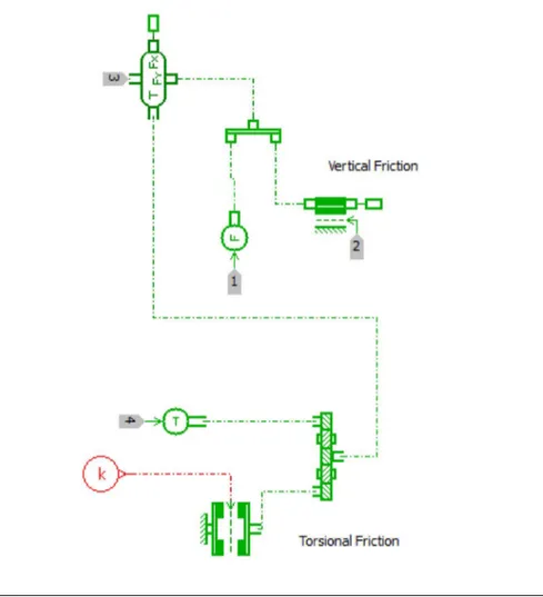
The block diagram of the system, resulted from the connection be-tween each subsystem is represented at Fig. 3.5 where each subsystem is connected.
Each of the blocks represent a subsystem of the model: the lock mechanism (LOCK) the door (DOOR), the plate (PLATE), the block that calculates the relative speed between the plate and the static friction at point D, as a function of the vertical speed and rotation of point B (REL-ATIVESPEED) and the resulting force transmitted at point B due to that force plus the friction already acting at point B (FRICTIONFORCE). At a point of the door, representing the handle, an input force is given by the
Figure 3.4: The higher the value of a, the closer Ff ris to the behavior of the
ideal dry friction
L E C H S A B D
The baseline interface: the door Its kinematic model Its physics model
The latch mechanism The hinge mechanism O A C B E D S H L K DOOR RELATIVE SPEED
Figure 3.5: Block diagram connecting each subsystem, relating to the physical system
user. The green line indicates mechanical linking (such as force application, state constraints), while the red line indicates dimensionless signals (state measures, numerical inputs, etc.) The door is linked to the plate, the fric-tion applied at the plate while it slides is calculated and act as an external force, along with the additional friction already present, at point B. The parameters that define our system are the technical specifications of the product, they include the dimensions and position of each relevant compo-nent, the spring stiffness, the force required to lock or unlock the door and the forces generated by each friction. The standard values for the variables occurs when the door is fully opened.
3.3.1.1 Subsystem DOOR
The door is modelled as a rod connected to the ground by a revolute joint. At the revolute joint, a constant dry friction is applied. At point 2, user force is applied; at point 3 the forces from the lock mechanism are applied, and at point 4 the angular position is measured and sent as an output and at point 1 the door is linked with the plate (Fig. 3.6). The important parameters are:
• L – length of the door;
• TatO – torque acting at joint O, due to friction;
• M – mass of the door;
• Iz – moment of inertia of the door at its barycentre; • (Gx,Gy) – centre of mass of the door;
• (LOA) – distance between points A and O.
3.3.1.2 Subsystem PLATE
The plate is a body connected at the door (point 7) by a revolute joint at point A, connected to the ground by a sliding joint at point B and to a spring at point C (Fig. 3.7).
Figure 3.6: Block diagram of the subsystem DOOR
Points 1-5 measure the normal force acting on the cabinet the vertical position, the rotation, the vertical speed and the rotational speed, respec-tively. They are used to calculate the friction at B, which enters as a force at 6.
At C a spring acts, along with friction, using only the vertical dis-placement and speed of point C. The important parameters are:
• FatC – force acting at point C due to friction;
• TatA – torque acting at joint A, due to friction;
• LBx – horizontal position of point B;
• LBy – initial vertical position of point B;
• LCx – initial horizontal position of point C;
• LCy – initial vertical position of point C;
• K – spring stiffness. • Fload – spring pre-load
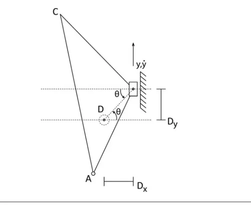
3.3.1.3 Subsystem RELATIVESPEED
This subsystem uses the vertical position and rotation measurements of the plate in relation to point B, and calculates the relative speed between the plate and the fixed friction at point D of the cabinet, which is then transformed into a torque and a force. It is denoted y the vertical position of point B in relation to point D, dy/dt its vertical speed, Dx the horizontal
position of point B in relation to D (which remains constant), Dy the vertical position of point B in relation to D at the initial state, θ the angular rotation of the body, with an initial value of atan(Dy, Dx) and dθ/dt the angular rotation and speed of the plate in relation to B. The relative speed VD between point D and the plate can be thought as the vertical speed of point B plus the distance R between D and B multiplied by the angular speed of the plate. That is:
R =py2+ D2 x (3.2) VDx = dθ dt R (−sin(θ)) (3.3) VDy = dθ dt R cos(θ) + dy/dt (3.4)
The angle formed between VD and the horizontal direction is
αVD = atan2(VDy, VDx) (3.5)
Once the relative speeds are computed, the forces applied due to the friction at point D can be computed:
FDx = FatD tanh(a VDx) cos(αVD) (3.6)
FDy = FatD tanh(a VDy) sin(αVD) (3.7)
These forces can be transferred to point B, where they are trans-formed into a vertical force and a torque acting at point B. Since point B cannot move horizontally, the force at the horizontal direction is neglected. The resulting torque is:
T = Dx FDy+ y FDx (3.8)
On the diagram (Fig. 3.9), the points 1-6 correspond to the following signals: • Point 1 – dy/dt • Point 2 – T • Point 3 – Dy • Point 4 – dθ/dt • Point 5 – y • Point 6 – θ
The most important parameters on this subsystem are:
• FatD – Friction force magnitude acting at the fixed point H from the
cabinet;
3.3.1.4 Subsystem FRICTIONFORCE
This subsystem (3.10) transform the signals of the subsystem REL-ATIVESPEED into a mechanical force and sums it with the friction already present at point B.
At point 1 enters the force signal and at 4 enters the torque signal, respectively, from the subsystem RELATIVESPEED. At point 2 enters the normal force applied by the slotted link. The torques and forces are summed, and then applied at the plate at the output 3.
The important parameters on this subsystem are:
Figure 3.11: System representation of the latch mechanism: the stiffness of the spring depends whether the system is being opened or closed
• µ – coefficient for the force of the vertical friction; • TatB – force acting at the slotted link, due to friction;
3.3.2 Latch mechanism
The latch mechanism resists to the force the user applies both when the user is trying to open and when trying to close. The deformation cannot be clearly felt by the user; instead, once a force threshold is crossed, the door opens (or closes). It can be thought as a very stiff spring that goes under compression, both during opening and closing. Therefore, we have a high stiffness spring/damper system where the force changes direction depending on whether the user is opening or closing the door.
The model is composed by 3 springs that are active only inside a limited interval: one for the opening phase, another for the closing phase, and another to represent the wall. The wall also has a damping term to dissipate the kinetic energy once it is touched. The wall is active for θ < 0, while the opening and closing phase are restricted at a custom range.
Figure 3.13: The force applied by the latch mechanism in function of the position of the door due to the spring. The force changes direction depending
whether the user is trying to lock or unlock the door
Looking at the block diagram (Fig. 3.12, at point 1 the force is applied at the door, while at point 2 the position of the door is used to define the values for the stiffness and damping values. In Fig. 3.13and Fig.
3.14, the graphics illustrate how the spring stiffness changes according to the position and the force applied by the latch mechanism in function of the position.
3.4
Measurements
The estimation of the relevant parameters of the dynamic model de-veloped requires quantitative analysis of the dimensions and behavior of the real system. The relevant distances were obtained by means of direct measurement while the remaining parameters were estimated by an opti-mization process that is explained on Chapter 5. The development of the virtual replica of the product also takes into consideration the qualitative behavior of the real product; simplifications and assumptions can be made
Figure 3.14: The stiffness of the latch mechanism changes according to the position of the door, they are related to the force required to lock or unlock the
door
based on the measurements. If it is considered that the our dynamic system has the following form:
˙x(t) = f (x(t), p) + g(x(t), p) Fu(t) x(0) = x0
(3.9) where x is the state of the system, x0is the initial condition, p = {p1, p2, ..., pi} is the vector that contains the parameters to be estimated and Fu(t) the input given by the user, the solution of the system can be written on the following form:
x(t) = h(p, Fu(t), x0, t) (3.10) If we can measure x(t) and Fu(t), knowing the initial condition x0, we should be able to find a set p that satisfies Eq. 3.9 as x(t), Fu(t) and the structure of f and g are known. Therefore, to estimate p, we measured and estimated the state and the input Fu(t). It is important to note, however, that there might be more than one set p that satisfies the imposed condition.
Therefore, while the set p found might not be equivalent to the real values that characterize the system, it is a set that generates an equivalent system, and satisfies the intended purpose.
The state x(t) is composed by the angular speed ( ˙θ) and angular position (θ). The entire state x(t) does not need to be fully measured, since:
θ(t) = Z
˙
θ(t)dt (3.11)
The measurement of the force applied by the user has been performed using a compression donut load cell (FUTEK model LTH300, www.futek.com) with a maximum detection load of 445N . The load cell has been mounted between participants’ hand and the door handle (as illustrated in Fig. 3.15) in order to measure the required opening force as a function of time. The estimation of the force required to lock and unlock the door can be readily obtained from the measured force: since no noticeable movement is per-ceived, measuring the state becomes unnecessary. However, when the door is locked, there is a range where some movement is allowed; it was measured through an inclinometer (Columbia Research Laboratories model SI-701B), with range of ±10◦. The estimation of the state of the system was per-formed through measuring the velocity in function of time with a gyroscope (British Aerospace Systems and Equipment unipolar gyroscope, able to de-tect angular velocities in the range of ±100◦/s), simultaneously measured with the force applied by the user. The signals have been acquired through the National Instruments NI cDAQ-9172 and NI 9125 analog input modules (www.ni.com) and processed through LabVIEW SignalExpress. All the sig-nals have been acquired with a frequency of 1024Hz. Three users have been asked to open the door by applying different forces with the sensors config-uration showed in Fig. 3.15. Subsequently the load cell has been glued on the external part of the door and the same users have been asked to close the door by applying different forces.
The sensors have been coupled in the following ways: first the load cell plus the inclinometer were used to detect what happened before the door is opened (the zero corresponding to the door closed) and then the
Applies a force to a body due to a mechanicalcomponent
Sensors responible formeasuring forces speed,velocity and acceleration
Converts a signalinputinto force/torque to be applied ata me-chanicalcomponent
Transform signalinputinto planarforces/torque to be applied ata planarbody
Figure 3.15: Location of sensors for the measurements performed on the com-mercial dishwasher [13].
load cell plus the gyroscope to understand the dynamic behaviour of the door. As it can be seen from Fig. 3.16 and Fig. 3.17, the is no detectable movement after 0.5◦, when the door is locked, until a threshold of force is crossed; the force required to unlock can be considered simply the peak of the graphic.
The behavior when locking the door is identical; the peak is taken as the force required to lock the door, the dynamic behavior is neglected.
When the door was fully open, an impulse is given and the angular speed is measured by the gyroscope. By looking at the graphics (Fig. 3.19
and3.20), that correspond to one trial, measured by the gyroscope and load cell, it is possible to observe that the angular speed decreases at approx-imately a constant rate once a force is no longer applied, thus it can be inferred that the main factor responsible for the deceleration comes from a constant dry friction.
It is noted that since the forces are by humans, the input of the sys-tem will always be significantly different for every trial and as a consequence, the output of the system will also be different for every trial. While the pair input/output are changes every trial, both in magnitude and shape, they are
Figure 3.16: Measured force when unlocking the door in function of time: the force required to unlock the door is characterized by the peak of the graphic
Figure 3.17: Measured position when unlocking the door in function of time: no noticeable displacement until the force cross a threshold
Figure 3.18: Measured force when locking the door in function of time: the peak of the graphic characterizes the force required to lock the door
still measuring the response of the same system, and so it is expected that the estimation of the parameters of the system does change significantly when done for each pair. The estimation is discussed in Chapter 5.
Figure 3.19: The measured angular speed in function of time shows that the angular speed decreases linearly, which indicates dry friction is the predominant
dissipative force
Figure 3.20: Measured input force in function of time: an impulse is given when the door is fully open
In this chapter, it is described the process of creating the haptic virtual prototype, detailing the device used, the adopted programming lan-guage and the strategies to mimic the tactile sensations derived from the dishwasher door.
4.1
Haptic Device
There are plenty of haptic interfaces commercially available today. Commercially, haptic devices come in two distinct classes impedance con-trolled devices, and admittance concon-trolled devices [15]. A well-known ex-ample of impedance control devices are the Phantom devices from Sensable. The paradigm on impedance control is this: the user moves the haptic de-vice, and the device will react with a force when the virtual object is met. From the haptic device point of view, displacement becomes the input, and the force is the output. The user will feel the mass and friction of the ac-tual device, though they can be made reduced through mechanical design. Impedance controlled devices tend to be naturally light and highly back-drivable, typically cable driven by DC motors. In contrast with impedance control, in admittance control the paradigm is this: the user exerts a force on the haptic device, and the device will react with the proper displacement. That is, force applied by the user becomes the input, while the displacement is the output. Admittance control allows backlash and tip inertia to be elim-inated, giving considerable freedom on the design of the device. This results in increased robustness, where high stiffness and high forces are possible. The device used for this work is based on the admittance control paradigm, the MOOG’s HapticMaster. While impedance control device tends to be lightweight, backlash free, but generally able to render low masses. Their performance is lacking if high stiffness or higher forces are required to be rendered. Admittance control devices, in contrast, are more suitable for
Figure 4.1: The workspace of the HapticMaster [16]
higher forces and stiffness, though they are not well-suitable for rendering low mass. The choice of using an admittance control haptic device comes due to the fact that our case study requires both high stiffness and higher forces . The HapticMaster measures the force exerted by the user, and an internal model calculates the position, velocity and acceleration which a virtual object touched in space would get as a result of this force [16]. This vector is commanded to the robot, which makes the movement by means of a conventional control law, rendered at 2500Hz, and can apply a forces up to 200N . A residual mass will always be present. The workspace of the HapticMaster is depicted in Fig. 4.1. It allows one rotation around its base and two translations, resulting in 3 degrees of freedom for the end effector, spanning a volumetric workspace. The HapticMaster allows the end effector to be changed for another, allowing us to mount the handle of the door at the end of the robot arm [16].
problems encountered when using this haptic device in conjunction with H3D API was related to its stability when higher stiffness was required to be rendered with explicit stiff functions. Even though the haptic device used for the application was designed for high stiffness, it still wasn’t able to properly render the forces when the user tried to lock/unlock the virtual door (when using explicit functions): the device became highly unstable once a threshold of stiffness was crossed, fairly inferior to the required one to properly reproduce the act of unlocking, and specially, locking the door. Additionally, there was a limit on the stiffness used to constrain the end effector to follow a specific trajectory the way we modelled. While it was not as stiff as a real dishwasher door, it still allowed to reproduce the movement with an acceptable fidelity. Regarding the smoothness, we detected that it did not translate so well when we tried to render dry friction as an hyperbolic tangent. Not only some background vibration could be sensed when moving the device around, but higher friction values (above 10N) would render the device highly unstable. Another limitation was related to the size of the workspace: it was not large enough, therefore the door had to be scaled down until it could fit entirely on the workspace. Unfortunately, none of the devices available had a workspace large enough. Even though these issues were present, and the virtual dishwasher door behavior did not fully equate with the real dishwasher door, the concept proposed on this study was successfully validated, and a better result would be obtained with a haptic device developed for this purpose.
4.2
Coding language and API
In order to control the haptic manipulation and then propose to the user different behaviors, the scripting language Python combined with H3DAPI [17] has been used for developing the interaction model and to re-trieve the values necessary to quantitatively describe the interaction phase in terms of displacement, acceleration and velocity. The H3D API is used as an interface to communicate the instructions from the computer to the haptic device, while Python scripts are responsible for calculating the force applied to the user by the end-effector. For contextualization, a brief de-scription of H3D API and Python are given.
4.2.1 H3D API
SenseGraphics H3D API is an open source software development platform for multi-sensory applications, using the open standards X3D, OpenGL and SenseGraphics haptics in a unified scenegraph taking, where both the haptic and graphic rendering are taken care of [17]. It consid-erably accelerates the development time, and can use Python scripting or C++ programming code for additional flexibility. It was chosen because not only it is compatible with HapticMaster, but also because it combines haptic-graphics into a single plataform.
4.2.2 Python
Python is a powerful dynamic, general-purpose, interpreted high-level programming language that is used in a wide variety of application do-mains [18]. Its design philosophy emphasizes code readability and allows the expression of concepts in fewer lines of code than other lower level program-ming languages, such as C. It supports multiple programprogram-ming paradigms, including object-oriented, imperative and functional programming styles.
4.2.3 X3D
X3D is a open standards file format and run-time architecture to represent and communicate 3D scenes and objects using XML. It provides a system for the storage, retrieval and playback of real time graphics content embedded in applications [19].
4.3
Haptic Model
The haptic model is the mathematical model responsible for com-puting the forces that the end-effector is subjected, the appropriate model should effectively mimic the desired behaviour. The equations used have
the form:
X = [x, y, z]
Fh = (Fhx, Fhy, Fhz) = F (X, ˙X)
(4.1) where Fh is the vector representing the forces that are applied to the end-effector, and X is the state of the system: the spatial coordinates of the end-effector and ˙X their derivatives.
In order to correspond the haptic model with the act of opening the door, the following points are addressed:
1. Describe the position of the door both in Cartesian coordinates and po-lar coordinates relating it with the description of internal coordinates of the end-effector by H3D API;
2. Constrain the movement of the end-effector to the same trajectory allowed by the door;
3. Evaluate what are the main effects influencing the tactile haptic sen-sation and describe them into equations.
The first point is addressed simply by evaluating the Cartesian coor-dinates displayed when the tracker position is requested, and then making an appropriate translation. The second point is addressed by defining the trajectory as an intersection between two surfaces, one in which the bound-aries have a circular shape with the same radius defined by the movement of the door (e.g. a sphere or a cylinder), and the other defined by a plane that contains the trajectory. The intersection constrains the end-effector by applying an attracting force proportional to a specified distance between the end-effector and the surfaces. As the proportional force tends to create undesired vibrations, damping was also applied.
In the third point, it should be noted that the main effects will be tuned in real-time. Therefore it is important to describe them in an ”intuitive” way: functions should represent sensations, not the dynamic pa-rameters from the real mechanism. Instead of using functions where the parameters correspond to a distance between two pivots or the specific fric-tion occurring on one of the sliding components, the effect perceived by the
user should be represented, i.e. the parameters should correspond to the ”easiness” or ”smoothness” of moving the door. This way, the operator can more easily understand how modifying a value affects his perception, e.g. to affect the ”smoothness”, the operator modifies the global friction, instead of the distance between two pivots. To do so, the equations responsible for calculating these forces were described directly in function of the angular position, and the parameters are changed to alter the magnitude of these functions.
4.3.1 Transformation of Coordinates
Since the trajectory traversed by the door is a semi-circumference, it is convenient to describe the position of the end-effector in polar coordinates. Since the force applied to the haptic device uses the state of the end-effector in Cartesian coordinates, when programmed in x3d, and the forces used in the model are described in cylindrical coordinates, a conversion becomes convenient.
The internal coordinate system of H3D, that we call Oi, describing the origin of the end-effector, is located at the geometrical center of the workspace (Fig. 4.1). To avoid the use of an angular coordinate outside the range of [0, π/2], the origin is translated one of the extremities of the workspace, from (0, 0, 0)i to (0, −0.158, −0.138)i, which becomes the origin of the new coordinate system, Om.
Denoting (posx, posy, posz)i the absolute position coordinates of the device on Oi the internal coordinate system, read by the software, the co-ordinates (x, y, z)m (whose index will from now on be suppressed) used for the equations are:
x = posx
y = 0.158 + posy z = 0.138 + posz
(4.2)
dx dt = dposx dt dy dt = dposy dt dz dt = dposz dt (4.3)
The force vectors are described as (F x, F y, F z) on Cartesian coor-dinates.
The equivalent coordinates and their time derivatives on the cylin-drical representation (x, r, θ) are:
r =py2+ z2 dr dt = y dydt + z dz dt py2+ z2 (4.4) θ = atan2(y, z) dθ dt = dy dt z − dz dt y y2+ z2 (4.5)
On vectors, a rotation matrix operation is applied, being the matrix of rotation:
Rot(θ) = cos(θ) sin(θ) −sin(θ) cos(θ)
!
(4.6)
The radial force Fr and the tangential force Fθ are:
[Fr, Fθ] = Rot(θ) [Fz, Fy] (4.7)
Conversely:
Note that the indexes y and z are inverted due to the way θ has been defined and due to how the rotation matrix has been assembled. The door is fully open when θ = 0 and fully closed when θ = π/2.
4.3.2 Constraining the end-effector
Here it is described generalized methods capable of describing the forces necessary to be applied the end-effector to restrict its movement to a given trajectory or surface. Two methods are developed: the first one for 2D curves described on polar coordinates, the second one for 3D continuous surfaces with continuous first derivatives. Both methods are based on the same idea: the end-effector is attached to a very stiff virtual spring-damper couple which equilibrium point is any point of the surface/curve. So, when-ever the end-effector position is outside the allowed region, a restitution force will be applied to bring it back.
4.3.2.1 First method: Radial direction stiffness
The first method, applied to 2D curves described by polar coordi-nates, consists on defining a spring on the radial direction, whose equilibrium point is a function of the angular position (Fig. 4.2). We define:
• P (x, y) a point representing the position of the end effector (on Carte-sian coordinates, though not necessarily the ones mentioned before); • R(θ) the function representing the curve, in polar coordinates, where
the origin coincides with the Cartesian coordinate system;
• Q(r, θ) the closest point to P on the radial direction (on polar coordi-nates);
• k the spring stiffness; • c the damping value.
Figure 4.2: Model for the spring acting on the radial direction of a curve: the force will always be oriented in the radial direction, though the equilibrium
point can change according to the curve we want the end effector to follow
• the angle that aligns P with Q and Q with the origin of the system:
θ = atan2(y/x); (4.9)
• the distance on x direction between P and Q:
∆x = x − r cos(θ); (4.10)
• the distance on y direction between P and Q:
∆y = y − r sin(θ); (4.11)
Therefore, the forces that bring the end-effector from point P to Q are
Fx= −k ∆x − c d∆x/dt Fy = −k ∆y − c d∆y/dt
If end-effector possess has a virtual mass m, and the user applies a force Fu = [Fux, Fuy], the differential equations that represents the move-ment of the end-effector are:
m¨x = Fx+ Fux m¨y = Fy + Fuy
(4.13)
The following example illustrates the dynamic behaviour of the end-effector numerically.
Example: Defining the trajectory as an ellipse on polar coordinates:
R(θ) = ab
(pa2 cos(θ)2+ b2 sin(θ)2) (4.14) Where: a = 0.2; b = 0.1; c = 20; k = 200. (4.15)
The end effector is set to have unitary mass and is set to begin at point (0.3, 0.3, 0). Since the initial point does not belong to the trajectory, the end effector is brought to it by the forces (Fx, Fy) (Fig. 4.3). At t = 3s a vertical force is applied at the end effector by the user (Fig. 4.4).
It can be seen that the trajectory is followed satisfactorily, and the absolute force applied by the haptic interface is acceptable (Fig. 4.5).
4.3.2.2 Second method: Restitution force based on distance mini-mization
The second method consists on finding the closest point Q(a, b, c) of a surface to P (x, y, z), and applying the a force at the direction Q − P
Figure 4.3: The end effector is brought to the trajectory from an initial posi-tion that does not belong to the ellipse
Figure 4.4: Impulse theoretically applied by the user at the end effector for the elliptical trajectory
Figure 4.5: Force magnitude that the haptic device should apply at the end effector to maintain it on the elliptic trajectory
that brings P to Q, and is the method used on this work to constrain the end-effector into the desired trajectory. Let us define a surface of class C2 on R3: g(a, b, c), and the distance d between Q(a, b, c) and P (x, y, z) as:
d(a, b, c)2 = (x − a)2+ (y − b)2+ (z − c)2 (4.16)
The problem becomes:
Minimize
(a,b,c) d(a, b, c) 2
subject to g(a, b, c) = 0
(4.17)
The optimization problem 4.17 can be solved by the Lagrangian method. The Lagrangian function L and the Lagrangian multiplier λ are introduced:
L = d2− λ ∗ g(a, b, c) (4.18)
∂L ∂a = 0 ∂L ∂b = 0 ∂L ∂c = 0 ∂L ∂λ = 0 (4.19)
The solution of the above system of equations gives us the coordi-nates of Q in function of the coordicoordi-nates of P. Unfortunately, it can’t always be solved explicitly. In that case, it would have to be solved numerically, which might or might not be possible to be done in real time. The force is: F = −k ∗(P −Q)−c∗( ˙P − ˙Q) = −k (∆x, ∆y, ∆z)−c (∆ ˙x, ∆ ˙y, ∆ ˙z) (4.20)
In our case study, the trajectory that the door describes is very simple; it can be represented by the intersection of a cylinder with a plane perpendicular to its main axes. The equation of the plane is x = 0, and the equation for the cylinder is y2+ z2 = R2 or r(θ) = R. The plane restricts the trajectory to x = 0, while the cylinder restricts it to a constant radius inside the plane.
It is evident that the minimum distance between a point and the plane x = 0 is exactly the value of the x coordinate. Therefore, force applied by the plane should be:
Fkx = −kx x − cx ˙x (4.21)
On the particular case of the cylinder, the radial distance coincides with the minimum distance, so both methods become equivalent. The equiv-alent physical example is a body connected to a spring attached to a revolute joint.
∂L ∂a = −2(a − x) = 0 ∂L ∂b = −2bλ − 2(−b + y) = 0 ∂L ∂c = −2cλ − 2(−c + z) = 0 ∂L ∂λ = b 2+ c2− R2 = 0 (4.22)
The group of equations (4.22) forms a non-linear system of algebraic equations. There are two solutions for this system in λ, a, b and c. The first solution is: λ = 1 − py 2+ z2 R a = x b = Ry py2+ z2 c = Rz py2+ z2 (4.23)
The second solution is:
λ = 1 + py 2+ z2 R a = x b = − Ry py2+ z2 c = − Rz py2 + z2 (4.24)
If we define: tan(θ) = y z (4.25) We can write: b = R sin(θ) c = R cos(θ) (4.26)
where both solutions are contemplated. The angle θ can be seen as the angle formed between the door and a horizontal plane.
The distance P − Q (in relation to the cylinder) is:
P − Q = (x, y, z) − (a, b, c) = (0, y − R sin(θ), z − R cos(θ)) (4.27)
If we define:
∆y = y − Rsin(θ) (4.28)
∆ ˙y = ˙y − ˙θRcos(θ) (4.29)
∆z = z − Rcos(θ) (4.30)
∆ ˙z = ˙z + ˙θRsin(θ) (4.31)
We have the forces acting on the end effector as:
Fky = −kr (∆y) − cr (∆ ˙y) (4.32)
Due to the damping term cr, there will be dissipation of energy of the system while the end effector moves around the trajectory, reducing its speed over time, which should not happen. However, the effect can be negligible for appropriate values of cr and kr, or, if it is not negligible, energy can be added through a ”negative damping” coefficient ce creating a force that acts tangent to the trajectory, removing or greatly minimizing this effect.
In the case of a cylinder, the forces that compensates the dissipation of energy has the following form (with ce > 0):
Fy e = ceRcos(θ) ˙θ (4.34)
Fz e= −ceRsin(θ) ˙θ (4.35)
In Fig. 4.6, it is shown that the end effector remains on the desired trajectory, given an initial speed. In Fig. 4.7 we can see the force being applied by the haptic device, and on Fig. 4.8 we compare the variation of kinetic energy between using an appropriate coefficient ce and not using it.
4.3.3 Haptic Behavior Modelling
This section describes the models that calculate the force feedback responsible for delivering the physical sensations during the act of opening the door. We divided into 4 phases: the unlocking phase, locking phase, the transition between the locked and unlocked state, and the phase where the door freely moves, which then are linked together into a single continuous equation. Part of the assessment of how the dominant forces behave has been done on Chapter 3, and it will be shown how the haptic behavior can be modelled after them.
Figure 4.6: Circular trajectory followed by the system given an initial speed
4.3.3.1 Activation functions
In order to join discrete behaviours into a continuous equation, the use of activation functions was adopted, i.e. functions that assumes the value of 1 or 0 depending on the input. A wide variety of sigmoid functions (functions that have an ”S” shape) can be used as activation functions, e.g. the hyperbolic tangent or the error function. The adopted function was based on the hyperbolic tangent:
Figure 4.7: Magnitude of the force required to constrain the movement of the end effector inside the desired trajectory
Figure 4.8: Kinetic energy variation when the end effector traverses 90◦, which depends on the value of ce
Figure 4.9: Effect of a coefficient on activation function
The above function tends to the step function as a increases. Therefore it is assumed:
S(θ, θ0) ≈ 1 for θ > θ0; (4.37)
S(θ, θ0) ≈ 0 for θ < θ0. (4.38)
4.3.3.2 Unlocking Phase
The unlocking phase corresponds to the situation where the door is being opened, where the force is applied by latch mechanism. The charac-teristics deemed relevant to represent the sensation were the faint pulling effect the door executes at the hand of the operator, on the region where some looseness can be felt (red square on Fig. (4.10)), and the maximum force necessary to unlock the door, on the rigid region (green circle on Fig. (4.10)).
Figure 4.10: Analysis of force required to unlock the door
These distinctive behaviors were modelled as a spring: the red region was modelled as a spring with low stiffness kl, while the green region was modelled as a spring with very high stiffness k∞. The angle where the stiffness change is called θ0, the angle where the door finally opens is called θ1. The activation function S is used as a transition between those regions. It should be remembered that the value of the angle when the door is closed is at its maximum, π/2, and it decreases as the door opens, so θ0 > θ1. The equation representing the force applied by the end-effector at the user is:
Fo = [kl(θ − π/2) − k1∞(θ − θ0) S(θ, θ0)] S(θ, θ1) (4.39)
4.3.3.3 Locking phase
The locking phase corresponds to the situation where the door is being closed, where the force is being applied by the latch mechanism. The behavior is identical to the yellow region on the unlocking phase, and thus is modelled as a very rigid spring, though the force goes in the opposite direction. For practical implementations, such as reducing vibrations or eliminating elastic collisions, a viscous damping c∞ is also added:
Fc= k2∞(θ − θ3) [S(θ, θ3) − S(θ, θ2)] − c∞θ[S(θ, θ˙ 3) − S(θ, θ2)] (4.40)
Where Fc is the force the haptic device applies, while θ2 and θ3 is the region where the locking phase is valid, being θ2 > θ3.
4.3.3.4 Transition between locked and unlocked state
Between the locked and unlocked state, there is a very small region where the door does not stay: it will either go back to the region where it is locked, or where it is unlocked. To force the haptic device to simulate that region, a negative viscous damping cn is used: the system becomes unstable at that region, and is forced to move away. Therefore:
Ft= cn θ [S(θ, θ˙ 2) − S(θ, θ1)] (4.41)
Where Ft is the force the haptic device applies, while θ1 and θ2 is the region where the transition phase is valid, being θ1 > θ2.
Since during the locking/unlocking phase theta is very small, the only relevant component of the force is on z direction.
4.3.3.5 Moving Phase
The moving phase corresponds to the situation where the door can move freely around its point of rotation. The analysis of the mechanism that controls the door indicates that dry friction is the most relevant effect. Measures confirm it: the velocity decays at an approximate constant rate, which implies a constant force opposing the movement is at work (Fig. 3.19). Therefore characteristic deemed most relevant was the friction, which should correspond to degree of ”smoothness”. The equation tries capture different kinds of ”smoothness”, in this case represented by dry friction and the asymmetry of forces caused by whether the angle is decreasing or increasing in value, at different positions. Forces responsible for returning the device
and viscous friction were also represented, even if they were not present on the original product. A force responsible to make the door return to an equilibrium position (such as automatically closing) is also present.
The term responsible for the viscous friction is:
Fv = −cv θ˙ (4.42)
A return force can be caused by a spring force, where the equilibrium point is at an angle θk, and its equivalent stiffness can change in function of position, if desired, and can be broken into different components arbitrarily, and i defines which component is being referred. The magnitude would be: Freti = −kreti(θ) (θ − θk) (4.43)
The dry friction is modelled as an hyperbolic tangent:
Fat = −cattanh(a ˙θ) (4.44)
The coefficient a defines the slope of the curve (on the same way of the activation function S) and cat corresponds to the friction force magnitude. We impose two different friction force magnitudes: one value when the door is closing ( ˙θ > 0) and another when the door is opening ( ˙θ < 0).
For ˙θ > 0: Fdry+ k = −c + at tanh(a ˙θ) (4.45) For ˙θ < 0: Fdry− k = −c − at tanh(a ˙θ) (4.46)


![Figure 3.15: Location of sensors for the measurements performed on the com- com-mercial dishwasher [13].](https://thumb-eu.123doks.com/thumbv2/123dokorg/7498892.104351/38.893.188.787.183.493/figure-location-sensors-measurements-performed-com-mercial-dishwasher.webp)