Alma Mater Studiorum
·
Università di Bologna
FACOLTÀ DI SCIENZE MATEMATICHE, FISICHE E NATURALICorso di Laurea Triennale in Informatica
Design and Implementation of the
µMPS2 Educational Emulator
Tesi di Laurea in Progetto di Sistemi Virtuali
Relatore
:
Prof. Renzo Davoli
Presentata da
:
Tomislav Jonjic
Sessione II
Design and Implementation of the
µ
MPS2 Educational Emulator
Tomislav Jonjic
Abstract
An arguably critical part of any computer science curriculum consists of experi-ence in designing non-trivial software systems. A first course in operating systems provides adequate ground for this endeavor, as any reasonably featured operating system is an intrinsically complex program. An operating system builds layers of ab-straction upon the bare machine interface; understanding—or better yet devising— such a system encourages one to acquire a solid command of software engineering principles and heuristics. Modern machine architectures, it is argued in this the-sis, are prohibitively complex and thus unsuitable as foundations for educational or experimental proof-of-concept operating systems. A preferable alternative, then, is provided by emulators of reasonably realistic but at the same time pedagogically sound hardware platforms. This thesis builds upon one such system, namely µMPS [1]—a tool primarily devised as an aid in operating systems and beginner-level com-puter architecture university courses. µMPS features an accessible architecture, cen-tered around a MIPS R3000 processor, that includes a rich set of easily programmable devices.
The first major revision of µMPS is the result of the present thesis. Among the prominent features of this new version, dubbed µMPS2 [2], are multiprocessor support and a more sophisticated and easier to use user interface. The primary goal of the architecture revision was to make the system reflect reasonably well modern commodity hardware platforms, for which the clear trend over the past several years has been a shift towards multi-core designs.
After an overview of the machine architecture and the emulator environment, a relatively thorough exposition of the emulator internals is given. Considerable care was taken to ensure that the code base is accessible enough to foster further experimentation, for which possible directions are given in the last chapter.
Progettazione e implementazione
dell’emulatore didattico µMPS2
Tomislav Jonjic
Sommario
Una componente importante di qualsiasi curriculum universitario di informatica è indubbiamente l’esperienza nella progettazione di sistemi software di non banale completessità. Un corso introduttivo di sistemi operativi rappresenta un contesto opportuno per questo scopo, visto che un sistema operativo è in generale un pro-gramma intrinsecamente complesso. Un sistema operativo va visto come una se-rie di livelli di astrazione, a partire da quello basato sull’interfaccia esposta dalla macchina stessa. La comprensione, ed a maggior ragione la progettazione, di un tale sistema non può prescindere da un’adeguata acquisizione di conoscenze dall’ambito dell’ingengeria del software. Le piattaforme hardware moderne, si sostiene in questa tesi, sono eccessivamente complesse, e di conseguenza non adatte come basi per sis-temi operativi didattici oppure quelli altamente sperimentali. Un’alternativa migliore consiste nell’impiego di emulatori di piattaforme hardware ragionevolmente realis-tiche ma allo stesso tempo di concezione espressamente didattica. Questa tesi è basata su un tale sistema, chiamato µMPS [1]—uno strumento ideato principalmente per l’impiego sia nei corsi universitari di sistemi operativi che quelli introduttivi di architettura degli elaboratori. µMPS vanta di un’archiettura pedagogicamente acces-sibile, in base alla quale si trova un processore MIPS R3000 e che include un’ampia serie di dispositivi facilmente programmabili.
Il primo considerevole aggiornamento di µMPS è il risultato della presente tesi. Tra le caratteristiche notevoli della nuova versione, denominata µMPS2 [2], trovi-amo il supporto multiprocessore e un’interfaccia utente più usabile e sofisticata della precedente. L’obbiettivo principale della revisione dell’architettura è stato quello di rispecchiare meglio con µMPS2 le comuni piattaforme hardware moderne, per le quali si è vista una chiara e crescente tendenza verso le architetture multi-core.
Dopo una panoramica dell’architettura di µMPS2 e dell’interfaccia utente, segue un’esposizione relativamente approfondita dell’implementazione dell’emulatore. Du-rante lo sviluppo di questo si è posta particolare attenzione alla mantenibilità e sem-plicità del codice, con lo scopo di incoraggiare futuri sviluppi; alcune direzioni pos-sibili per questi sono date nell’ultimo capitolo.
Contents
1 Introduction 1
1.1 Background . . . 1
1.2 The µMPS Project . . . . 2
1.3 Applications of µMPS . . . . 3
1.4 Contributions of This Work . . . 4
1.5 Organization of this Document . . . 4
2 An Overview of the µMPS2 Architecture 7 2.1 Introduction . . . 7
2.2 Overall System Structure . . . 7
2.3 Processor Architecture . . . 8
2.3.1 µMPS2-Specific ISA Features . . . 8
2.4 Devices and Interrupt Management . . . 10
2.4.1 Interrupts in µMPS2 . . . . 10
2.4.2 Interrupt Line Assignment and Source Resolution . . . 11
2.4.3 Interrupt Management in Multiprocessor Systems . . . 11
2.5 Higher Level Abstractions Through Firmware . . . 11
2.5.1 Higher-Level Exception-Handling Interface . . . 12
2.5.2 Higher-Level Virtual Memory Interface . . . 12
2.6 Further References . . . 13
3 The µMPS2 Emulator: A User’s View 15 3.1 Introduction . . . 15
3.2 User Interface Organization . . . 15
3.3 Machine Configurations . . . 16
3.3.1 Installed Devices and Device Files . . . 18
3.3.2 Byte Order in µMPS . . . . 18
3.4 Machine Control and Monitoring . . . 19
3.4.1 Startup and Shutdown . . . 19
3.4.2 Execution Control . . . 19
3.4.3 Breakpoints and Suspects . . . 21
3.4.4 Examining Processor State . . . 22
3.4.5 Memory View . . . 23
3.4.6 Device Monitoring . . . 24 i
ii Contents
3.4.7 Terminals . . . 24
3.5 Programming for µMPS2 . . . . 25
3.5.1 ROM Images . . . 25
3.5.2 The Toolchain . . . 26
3.5.3 Object File Formats . . . 27
3.5.4 Operating System Bootstrap . . . 27
3.6 Further References . . . 27
4 µMPS2 Emulator Internals 29 4.1 Design Principles and Overall Structure . . . 29
4.1.1 Signals, Slots, and the Observer Pattern . . . 30
4.1.2 Portability and the Choice of Implementation Language . . . . 30
4.1.3 Source Tree Structure . . . 31
4.2 The Emulation Core . . . 32
4.2.1 Machine Configurations and Machine Instances . . . 33
4.2.2 Processor Emulation . . . 34
4.2.3 Device Emulation . . . 37
4.2.4 Virtual Time, Machine Cycles, and Event Management . . . 38
4.2.5 Debugging Support . . . 39
4.2.6 High-Level View of the Emulation API . . . 39
4.3 The User Interface Implementation . . . 40
4.3.1 The Qt Framework . . . 40
4.3.2 Models and Views . . . 40
4.3.3 Machine Execution . . . 41
4.3.4 Class and Module Overview . . . 44
4.4 µMPS2 Object File Support Tools . . . 46
4.4.1 ELF to .aout Conversion . . . 46
5 Conclusions 51 5.1 Suggestions for Further Experiments . . . 51
5.1.1 Detailed Simulation . . . 51
5.1.2 Emulator Scalability . . . 52
5.1.3 An Operating System for µMPS2 . . . . 53
A µMPS2 Architecture Revision 55 A.1 Machine Control Registers . . . 55
A.1.1 Processor Power States . . . 56
A.1.2 Processor Initialization . . . 56
A.1.3 Powering Off the Machine . . . 57
A.2 New and Revised CP0 Registers . . . 57
A.2.1 PRID Register . . . 57
A.2.2 The On-CPU Interval Timer . . . 58
A.2.3 Status Register . . . 59
Contents iii
A.3 Multiprocessor Interrupt Control . . . 59
A.3.1 Interrupt Distribution . . . 59
A.3.2 CPU Interface Registers . . . 60
A.3.3 Inter-processor Interrupts (IPIs) . . . 61
A.4 New Instructions . . . 63
A.4.1 Compare and Swap (CAS) . . . 63
A.4.2 Wait for Event (WAIT) . . . 64
A.5 BIOS Services . . . 64
A.6 Device Register Memory Map . . . 65
List of Figures
3.1 The main window . . . 16
3.2 General machine configuration parameters . . . 17
3.3 Device settings . . . 18
3.4 The main window’s processor tab pane . . . 21
3.5 The breakpoint insertion dialog . . . 22
3.6 The processor window . . . 23
3.7 The main window’s memory tab . . . 24
3.8 Device status view . . . 25
3.9 The terminal window . . . 26
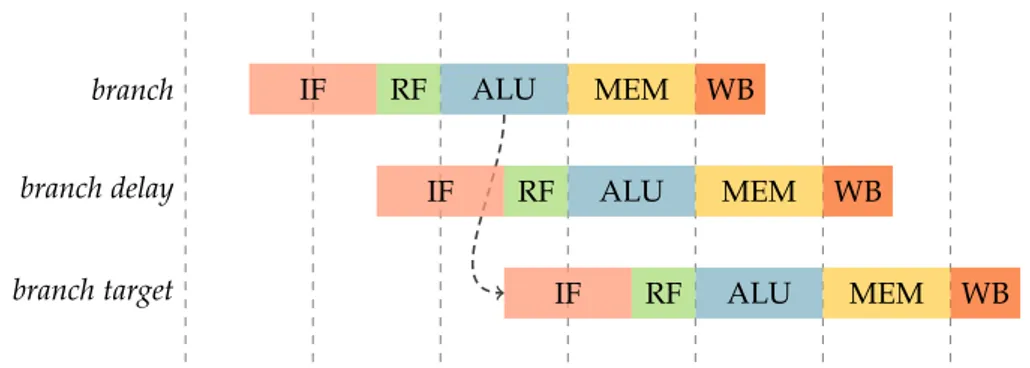
4.1 The MIPS five-stage pipeline and delayed branches . . . 36
4.2 The model-view architecture of the µMPS2 emulator . . . . 42
A.1 Processor power states . . . 56
A.2 The Status CP0 register . . . . 59
A.3 IRT entry format . . . . 60
A.4 IRT register address map . . . . 61
A.5 The TPR register . . . . 61
A.6 The Outbox register . . . . 62
A.7 The Inbox register . . . . 62
A.8 Device register memory map . . . 65
List of Tables
A.1 Machine control registers address map . . . 55
A.2 CP0 registers . . . 57
A.3 Interrupt line assignment in µMPS2 . . . . 58
A.4 Interrupt controller processor interface register map . . . 61
Listings
4.1 A sample machine configuration. . . 33
4.2 A linker script for .aout executables. . . 48
B.1 A JSON Schema for the µMPS2 machine configuration format. . . . . 67
Notational Conventions
Several notational and typographical conventions are employed throughout the text: • A bold typewriter-like typeface is used for machine registers (including
pro-cessor registers and device registers) and register fields, as in Status; • R.F denotes the field F of register R;
• Processor exception mnemonics are typeset in italic, as in AdES;
• A typewriter-like typeface is used for instructions, file names, identifiers, and code fragments, as in jalr.
Chapter 1
Introduction
1.1
Background
We begin this exposition with a brief account of the motivations behind the original work we build upon in this thesis. Rather than for its own interest or value, we choose to do so mainly because it will help elucidate many design choices described later on in this document.
Most computer science curricula have for a long time included a course in op-erating systems [3, 4]. This is rather fortunate, since many other areas of computer science find application in operating systems and, conversely, many notions stud-ied within operating systems research are likely to be useful in other subfields of computer science. Operating system kernels of even moderate sophistication will undoubtedly make use of a variety of well known algorithms and data structures. An undergraduate course in operating systems also represents a very natural setting for a first introduction to concurrency. Finally, the course offers an outstanding op-portunity for the student to review the engineering aspects of computer science. An operating system is an inherently complex computer program, whose design and im-plementation ultimately depends on the student’s ability to apply sound techniques of abstraction to manage an otherwise overwhelming complexity. By participating in the design and implementation process, the student can acquire experience in structuring large software systems in general.
For reasons we have outlined above, a course in operating systems should, rather than adopting a purely descriptive approach, ideally include in its program the study and possibly an implementation of a complete operating system. Such an approach to teaching operating systems is by no means new, as evidenced by several influential textbooks devised, at least in part, to support it. As notable examples, we mention Lions’ book on the 6th edition UNIX system [5], Bach’s book on the internals of UNIX System V Release 2 [6], and Tanenbaum’s book on MINIX [7]. Beside having had considerable influence on future operating systems course curriculums, it is not unreasonable to argue that the aforementioned works had an impact on the industry as well. All of the mentioned books describe existing, complete, operating systems. At the other extreme, the instructor may choose to assign the task of designing and
2 Chapter 1. Introduction
implementing the operating system to students (with proper guidance, of course). While both approaches unquestionably have their own merits, the latter arguably results in educationally more rewarding experiences [8, 9].
An instructor that chooses to assign the task of developing an operating system to students is unavoidably posed with a problem: which machine architecture should the course target? One obvious answer would be to simply use any variant of mod-ern architectures currently in use—after all, shouldn’t one focus on technologies that are relevant today and thus likely to remain so for the foreseeable future? Unfor-tunately, modern hardware is overwhelmingly complex—coming to terms with the quirks and complexities of today’s hardware would simply take a disproportionate amount of time for a typical one-semester course. µMPS is an educational computer system architecture and emulator that was designed specifically to be pedagogically sound: it provides a streamlined version of most features typically found on mod-ern computer systems. We argue in this thesis that µMPS is an ideal fit for the above-mentioned use case.
1.2
The µMPS Project
The goal of the µMPS project, as was already noted, has been to develop a computer system architecture and supporting software— that is, the “courseware”, of which the machine emulator constitutes the most important part—especially tailored to computer science education. This reflects in two often contrasting requirements: on one hand, the architecture should be representative of real ones (that is, reasonably realistic), and on the other hand it should be considerably simpler than those.
The original version of the architecture and accompanying courseware, called MPS [10], were authored at the University of Bologna by Mauro Morsiani, under the supervision of Renzo Davoli. The system was centered around a single MIPS R3000 processor, a member of the MIPS architecture line, which was at the time al-ready becoming well established in computer science education as a prime example of an elegant, clean, instruction set architecture. The system specification also de-tailed a rich set of peripheral devices and a system bus along with their supporting controllers. Later revisions of the architecture and courseware, including the latest
µMPS2, remained identical in spirit to the original version. (We present a brief
intro-duction to the architecture in Chapter 2; for a detailed and authoritative description we refer the reader to [11].)
µMPS [1] was a slight evolution of MPS, motivated by the experience and
feed-back from using MPS in undergraduate operating systems courses taught by Renzo Davoli at the University of Bologna and Michael Goldweber at Xavier University. On a hardware level, this version introduced a streamlined and more orthodox virtual memory subsystem. Interestingly, the new virtual memory subsystem was imple-mented almost entirely using ROM level abstractions and required only minor mod-ifications to the processor architecture. On the emulator level, µMPS featured a more novice-friendly graphical user interface.
1.3. Applications of µMPS 3
The µMPS architecture is, as of writing, in its second major revision, labeled
µMPS2, and implemented by the 2.x series of the emulator. Multiprocessor support
is the single most important feature of µMPS2. With this addition, µMPS remains comparable in feature with the current generation of consumer-class computer sys-tems.
1.3
Applications of µMPS
The original inspiration for the µMPS project, and perhaps still the driving motiva-tion and most important use case, is the one we have already given above: to provide a didactically sound hardware platform for use by educational—whether academic or hobby—operating system projects. We see µMPS as ideally suited for this use case because it represents an acceptable compromise between realism and simplicity. In-deed, the current revision of the architecture does not deviate appreciably from that of a contemporary workstation or small server class system. At the same time, the various hardware subsystems in µMPS exclude the gratuitous complexity present in virtually all real-world hardware that would unnecessarily hinder the learning process.
µMPS can also be a valuable aid in a first introduction to MIPS assembly
lan-guage programming. This topic is often selected as a small but important part of an introductory course in computer architecture, since it can help explicate many aspects of the hardware/software interface. An assembly level MIPS simulator such as SPIM [12] or MARS [13] is typically used to execute programs written in MIPS assembly. Unlike µMPS or other emulators, these programs do not interpret actual machine code; instead, they interpret MIPS assembly language programs directly. Consequently, using µMPS requires slightly more effort compared to an assembly simulator, since a development toolchain (an assembler and linker at minimum) is needed to prepare programs for the machine. The features provided by µMPS, such as its support for many peripheral devices or the emulator’s debugging features may well be worth the additional effort.
Finally, we believe that µMPS provides a good basis for experimentation in com-puter system emulation, especially in the area of educational applications. The pri-mary reason for this is the relative simplicity of the µMPS system and emulator, compared to prominent full system emulators, such as QEMU [14]. Since these em-ulators are expected to efficiently execute real-world operating systems and realistic workloads, they put first and foremost an emphasis on performance, at the cost of code complexity. As such, these highly optimized systems are inevitably both less suited for experimentation and less amenable to extensions. We give some possible directions for future extensions in Chapter 5.
4 Chapter 1. Introduction
1.4
Contributions of This Work
Only several years ago, consumer desktop systems were virtually without exception uniprocessor systems. Multiprocessor architectures were economically viable only for server systems and, to a lesser extent, specialized high-performance worksta-tions. In the meantime, however, the industry has has shifted focus to multiproces-sor designs for high-end and commodity systems alike. This was primarily a result of ever more diminishing returns from instruction-level parallelism and of power is-sues. Multi-core machines are now ubiquitous on desktop or even mobile hardware and this trend is most certainly going to continue. As a result, general purpose op-erating systems designs—whether educational or not—that target only uniprocessor systems are at the very least considered obsolete. The single processor design of
µMPS was in this regard a serious limitation.
This thesis resulted from the attempt to bring µMPS to the era of thread-level par-allelism. µMPS2 includes relatively sophisticated multiprocessor support, modeled after existing hardware but appreciably streamlined in comparison.
Extending the µMPS emulator to support the µMPS2 architecture created an op-portunity to reconsider various design choices behind the emulator. An important aspect—certainly the most visible to end users—in which the µMPS2 emulator dif-fers from its predecessors is the user interface, which has been redesigned to better fit modern user interface standards and the expectations of today’s users.
1.5
Organization of this Document
This chapter introduced µMPS, its scope, and its use. In the remainder of this work, we present an overview of the µMPS2 architecture and emulator (referring the reader to the official documentation for full details) as well as information on the emulator internals.
Chapter 2 outlines the µMPS2 architecture. Although finer details of the archi-tecture are not given (such as device controller programming information or details on machine registers), it contains enough background material to allow the reader unfamiliar with the architecture to follow later chapters. In addition, Appendix A describes in detail the changes in the µMPS2 revision of the architecture.
Chapter 3 gives a user’s perspective of the µMPS2 emulator. It describes the most important parts of the user interface and the means by which emulated machines can be created and executed.
Chapter 4 dwells on the internals of the µMPS2 emulator. The material will especially be of interest to the reader who is required to understand the emulator code (that is, the prospective maintainer or contributor). Both the emulation back-end and the front-back-end (user interface) components are described in fair detail.
Finally, in Chapter 5 we attempt to give an objective view on the overall success of the µMPS project thus far. We also list possible directions for future work. In particular, an ongoing experimental project is described that aims to mitigate the
1.5. Organization of this Document 5
multiplicative slowdown due to emulation of multiprocessor machines, by exploiting thread-level parallelism at the host level (at the expense of deterministic execution).
Chapter 2
An Overview of the µMPS2
Architecture
2.1
Introduction
The µMPS hardware platform is, by design, considerably easier to program than ones typically found in actual computer systems today. This design goal is reflected both in the choice of the base instruction set architecture and (especially) the device controller interfaces that comprise the system. In this chapter, we briefly describe these design choices and give a short overview of the µMPS2 architecture, with the intent to present just enough details to allow one to comfortably follow the remainder of this work.
2.2
Overall System Structure
µMPS2 includes features commonly found in a modern server or workstation class
multiprocessor machine, albeit in simplified form. In a nutshell, the µMPS2 com-puter system is composed of:
• Up to sixteen MIPS R3000-style processors (µMPS2-specific parts of the instruc-tion set architecture are described in Secinstruc-tion 2.3).
• Device controllers for five device types (terminals, disks, tape readers, printers, and network adapters).
• Various support hardware, including a programmable multiprocessor interrupt controller.
• A system bus connecting the above units. The bus controller integrates a sys-tem clock and an interval timer. These devices are interfaced through a mem-ory mapped register interface, which also includes registers that provide criti-cal system information.
8 Chapter 2. An Overview of the µMPS2 Architecture
2.3
Processor Architecture
The µMPS2 processor architecture is based on the one implemented by MIPS Com-puter System’s R2000 and R3000 models, the earliest members of the MIPS line of processors. This architecture, labeled MIPS-I, grew out of the research project of the same name at Stanford University, led by John L. Hennessy [15]. The key insight be-hind the project was that an instruction set composed of relatively simple operations was amenable to an efficient implementation using the technique of pipelining, the first of many micro-architectural techniques that were used by subsequent designs to exploit instruction level parallelism. The MIPS design was commercialized in 1986 by MIPS Computer Systems Inc., in the form of the R2000 processor.
The choice of instruction set architecture (ISA) was motivated by the MIPS archi-tecture’s virtue of being both didactically sound and well supported by existing com-pilers and tools. The MIPS-I instruction set is arguably the most elegant 32-bit ISA among those server and workstation-class architectures that have seen widespread adoption in the industry. The best evidence of this is its use in computer science education; as just one concrete example, we mention Hennessy and Patterson’s in-fluential introductory textbook on computer architecture [12].
2.3.1 µMPS2-Specific ISA Features
The instruction set implemented by the µMPS2 CPU is, from a user-level
program-ming perspective, a strict superset1 of the MIPS-I ISA, as implemented by the R2000
and R3000 processors. This is of fundamental importance for the µMPS project, since this level of (backward) compatibility means that µMPS can be automatically supported by existing MIPS compilers.
It is in the system control coprocessor (known as CP0 across MIPS architecture revisions) inteface—relevant from a system programming perspective—that µMPS2 slightly departs from the R3000 processor. Such incompatibilities are irrelevant for compiled code and most (if not all) higher-level software in general, since the CPU control interfaces are never targeted by compiled code. Indeed, prior to the MIPS32/64 revision of the MIPS architecture, the system control coprocessor’s in-terface was implementation dependent; in this sense, the µMPS2 CPU is a strictly conforming implementation of the MIPS-I ISA.
Memory Management Support
Like the R3000 family of processors, the µMPS2 processor integrates support for a paged memory management scheme; the key hardware unit behind this sup-port is the on-chip translation lookaside buffer (TLB), which in µMPS2 is of user-configurable size. On all MIPS architectures, the TLB is entirely software-managed;
1
µMPS2 does not include floating-point support, an optional part of the MIPS-I ISA defined in the
2.3. Processor Architecture 9
the notion of page table in particular is not defined by the hardware architecture at all.
Program (or “virtual”) addresses in the R3000 and any later MIPS CPU are always subject to a form of translation—a program address is never equal to the effective physical address output by the CPU. µMPS2 introduces two modes of operation for the processor’s memory management subsystem:
• a physical memory mode for which address translation via the TLB is not em-ployed and program addresses correspond to physical ones in a straightfor-ward manner;
• a virtual memory mode, in which address translation is used for all addresses apart from those in the range reserved for memory mapped I/O and ROM code.
As described in Section 2.5.2, the standard firmware supplied with µMPS2, build-ing on the low-level virtual memory support, introduces a hybrid segmented-paged scheme which is for most purposes more convenient from an operating system’s programmer perspective.
Cache Control
Most architectural components of the R3000 used specifically for cache management are not included in µMPS2. This is for instance the case with all the fields in the R3000 CP0 Status registers that are used for cache control and diagnostics. From a practical point of view, each µMPS2 processor can be thought of as fully cache-coherent.
Integrated Interval Timer
Like recent MIPS processors, each µMPS2 processor includes an on-processor pro-grammable interval timer. Readers familiar with the MIPS32/64 architecture revi-sions should be wary that, while the timer performs the same function as the one provided by the MIPS32/64 Count and Compare registers, it exposes a different programming interface.
Instruction Set Extensions
In addition to features added via the implementation-specific CP0 registers, µMPS2 augments the core MIPS-I instruction set with some new instructions:
• The wait instruction, borrowed from newer MIPS ISA revisions, is used to pause the CPU until an external event occurs. This instruction is analogous to the HLT instruction in the x86 architecture, for example.
10 Chapter 2. An Overview of the µMPS2 Architecture
• The cas instruction is a version of the well known and-set (or compare-and-swap) atomic instruction, adopted by several contemporary architectures,
among which are SPARC v9 and x86-64.2
2.4
Devices and Interrupt Management
µMPS2 supports device controllers for five different types of peripheral devices:
• Disk devices
µMPS2 disk devices are classic DMA-capable hard disk drives of configurable
geometry. • Tape devices
Tape drives in µMPS2 are read-only devices. Like disks, tape devices support DMA.
• Network devices
µMPS2 supports DMA-capable Ethernet adapters.
• Printer devices
Printers in µMPS2 are text-only output peripherals, attached on a 8-bit parallel interface.
• Terminal devices
These devices, used for text input and display, are a simplified version of the classic serial text terminal. Terminal devices are physically divided into two devices: a transmitter and a receiver.
Up to eight instances of each device type can be included in any µMPS2 machine, each one supported by the corresponding device controller. Device controllers are programmed via memory mapped hardware registers. The register-level interface is to a large extent uniform across device types.
2.4.1 Interrupts in µMPS2
All device controllers in µMPS2 support an interrupt-driven programming model: a device operation is requested by setting appropriate hardware registers; upon com-pletion, an interrupt is generated and device registers are updated accordingly; the
2MIPS architectures levels starting from MIPS-II include a pair of instructions called load-linked and
store-conditional (LL/SC) instead of CAS for the purpose of building synchronization primitives. Em-ulating LL/SC efficiently proves to be considerably more difficult, however. Since compatibility with MIPS-II and later instruction sets was not a requirement for µMPS2, this was an important consid-eration in the selection of an atomic read-modify-write primitive for µMPS2. As shown in [16], the expressive power of compare-and-set matches that of LL/SC. Furthermore, CAS and LL/SC are uni-versal primitives, which means, in simple terms, that they can be used to implement a non-blocking implementation of any other atomic read-modify-write sequence. The same is not true of some other well known atomic read-modify-write primitives, such as test-and-set or fetch-and-add.
2.5. Higher Level Abstractions Through Firmware 11
interrupt is acknowledged by issuing a new command to the device or by an explicit acknowledge command. The hardware does not provide any support for interrupt prioritization, but such schemes can be easily implemented in software.
2.4.2 Interrupt Line Assignment and Source Resolution
The various interrupt sources in µMPS2 are statically assigned to CPU interrupt lines (the lines represented by the IP field of the Cause register). All interrupts originat-ing from disk controllers, for example, are assigned to interrupt line 3. While slightly inflexible, the advantage of this scheme is that it does not require configuration at the hardware level nor complex probing mechanisms from the operating system. Devices of the same class (i.e. devices sharing an interrupt line) are distinguished by a device number.
Because multiple interrupt sources can in general be assigned to the same line, a discovery mechanism is needed to determine which (if any) interrupts are pending at any given moment. The interrupt controller’s memory mapped register interface includes a data structure, called the interrupting devices bitmap, which at any time indicates the interrupt state of all active sources. An analogous structure, called the installed devices bitmap, indicates which of the interrupt sources assigned to devices are active.
2.4.3 Interrupt Management in Multiprocessor Systems
The hardware parallelism of a multiprocessor system can be exploited by the operat-ing system to improve interrupt servicoperat-ing. Usoperat-ing multiple CPUs to service interrupts can potentially lead both to reduced interrupt latency (the elapsed time between the generation of the interrupt and the invocation of the respective handler routine) and increased throughput.
µMPS2 allows for fine-grained control over the distribution of interrupts to
avail-able processors. The operating system can specify the manner in which interrupts from individual sources are distributed to target CPUs by appropriately initializing a structure called the interrupt routing table (IRT). This structure consists of a set of memory mapped registers, each of which specifies interrupt routing parameters for a single interrupt source (e.g. the second disk device).
2.5
Higher Level Abstractions Through Firmware
In order to function properly, a µMPS2 machine needs to be supplied with some basic ROM code. In particular, two architecturally-defined exception entry points (one for TLB related exceptions and another for all other exceptions) lie in the ROM code region. The standard µMPS2 ROM code provides some exception processing and TLB-handling services that are likely to be more convenient to use for most OS authors than the plain hardware facilities.
12 Chapter 2. An Overview of the µMPS2 Architecture
The interfaces described in this section, unlike those covered earlier, are not strictly part of the µMPS2 “architecture”; instead, they are higher level abstractions devised to make µMPS2 more approachable by beginners. These interfaces are im-plemented via the standard ROM code (i.e. the µMPS2 “firmware”) and their use is entirely optional; indeed, it is reasonable to expect that some OS authors will want to supply their own ROM code.
2.5.1 Higher-Level Exception-Handling Interface
The MIPS architecture provides minimal support for exception handling. After an exception is triggered, only information that is strictly necessary to discover its cause is placed in control coprocessor registers. In particular, the processor does not save any registers to memory on an exception. Similarly, control is transferred to one of the two predefined exception vectors, despite the variety of exception types defined by the architecture (interrupts, TLB-related exceptions, system calls, program errors, etc.).
The above is in stark contrast to the elaborate exception-handling support pro-vided by architectures such as the x86. The µMPS2 ROM code in effect emulates some of the exception-processing support offered by CISC-like architectures. Most importantly, the ROM exception handler supports automatic saving and restoring of whole processor states: on any exception, the CPU state is saved in a previously agreed upon location for the type of exception in question; similarly, control is trans-ferred to the OS by loading a CPU state from an OS-initialized location. (In the
µMPS2 documentation, these locations are referred to as the new and old processor
state areas.)
2.5.2 Higher-Level Virtual Memory Interface
The basic hardware support for virtual memory in the MIPS architecture is very rudimentary. The hardware has no notion of a page table, and consequently the
burden of managing the TLB (and in particular that of TLB refill3) falls entirely to the
OS. This is very much different from the x86-like paging model, typically described in textbooks on operating systems. Support for a rather traditional segmented-paged scheme has been thus added to µMPS, and it consists of:
• definitions of page table and segment table formats; • extended page table-related exception types.
Like the extended exception handling support described above, this abstraction is supported by the standard execution ROM code. On (architecturally defined) TLB
3Once again, the delegation of the TLB refill mechanism to software is typical of RISC architectures,
and MIPS in particular. Since TLB refill exceptions are relatively frequent in a system running an operating system that supports virtual memory, the hardware does offer some support in this case, however. In all MIPS CPUs, TLB refill exceptions are for performance reasons given a separate entry point, to avoid the cost of a dispatch to an exception handler subroutine.
2.6. Further References 13
refill exceptions, the ROM TLB exception handler is invoked. The task of this handler is that of inserting (if possible at all) the missing translation entry in the TLB or, if the entry cannot be found in the page table, “pass up” the exception to the OS.
2.6
Further References
The µMPS2 machine architecture that was outlined in this chapter is defined in [11]. The reader familiar with µMPS will find in Appendix A a description of all the changes from the earlier version of the architecture.
The MIPS I instruction set architecture—on which µMPS and µMPS2 are based— is detailed in [17], among other places.
Chapter 3
The µMPS2 Emulator: A User’s
View
3.1
Introduction
Using a hardware emulator, as opposed to a physical machine, for the task of de-veloping a program for an unhosted environment (e.g. an operating system) comes with enormous advantages. As an example, the tedious task of rebooting a physical machine in order to reload a modified operating system reduces to a simple recom-pilation of the program followed by a suitable “reload” command to the emulator. Likewise, an emulator is usually a far more convenient debugging environment than a physical machine. Debugging capabilities can either be supported by the emulator itself, or by way of an interface to an external debugger.
This chapter describes the µMPS2 user interface environment and the means which the µMPS2 emulator puts at programmers disposal for debugging guest code. We also include basic information on the host side of the development environment— that is, the process of preparing programs for execution under the emulator.
3.2
User Interface Organization
The machine monitoring and debugging features present in µMPS2 result in a large amount of information at the presentation level. To avoid excessive clutter, the
µMPS2 user interface (UI) is arranged into several top-level windows:
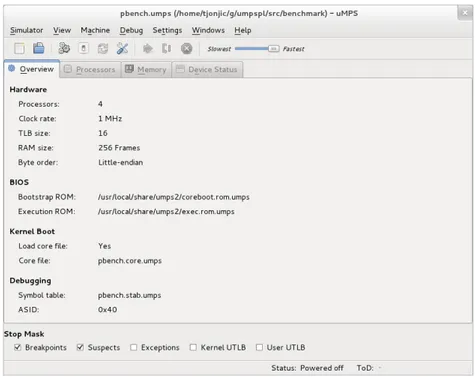
• The main window, shown in figure 3.1, is the central application window in
µMPS2 and the only one visible by default. In its four tabbed sections, it
dis-plays machine status information and contains most of the UI elements related to machine execution control, including debugger-related variables. We de-scribe each tabbed section in more detail at appropriate points below.
• Information about each processor is shown in the aptly named processor win-dow. Displayed data includes processor registers, translation lookahead buffer
16 Chapter 3. The µMPS2 Emulator: A User’s View
(TLB) entries, and a disassembly of the currently executed section of the pro-gram.
• For each terminal device in µMPS2, there is a top-level terminal window that acts as its front-end.
Figure 3.1: The main window. The central content is divided into four tabbed sec-tions: overview, processors, memory, and device status.
Aside from the top-level windows, several transient windows (i.e. dialogs) are used for such tasks as editing machine configurations and breakpoint insertion.
The µMPS2 user interface is fairly flexible and configurable. For instance, win-dow layout (placement and dimension) is persisted across sessions (at least for desk-top environments that support this feature). Likewise, within single windows several elements—such as the presence and size of various sub-panes—can be customized.
3.3
Machine Configurations
In order to accomplish anything useful, the emulator must be provided with a ma-chine configuration. A mama-chine configuration consists of parameters which define all modifiable aspects of the emulated hardware environment. We can group the configuration parameters into the following categories:
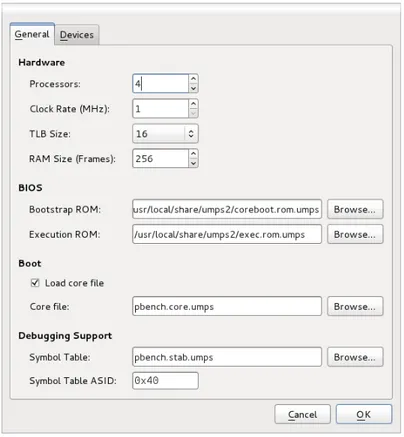
• Basic hardware characteristics. These include the number of processors, their respective characteristics, and the amount of installed RAM.
3.3. Machine Configurations 17
• Device information. These parameters allow the user to specify the set of in-stalled peripheral devices.
• ROM images. Two ROM image files must be provided: the bootstrap ROM and the execution ROM.
• Debugging parameters. These include, most importantly, the symbol table file. • Bootstrap settings. Parameters pertaining the bootstrap process are specified
here.
Machine configuration files in µMPS2 use a JSON-based [18] syntax. The user is not required to learn this syntax, however, since all configuration parameters can be set using the graphical user interface. Figure 3.2 shows part of the machine configuration dialog.
Figure 3.2: General machine configuration parameters.
At any given time, only a single machine may be loaded in an instance of the emulator. This is, however, not a significant limitation, since multiple application instances may naturally be launched, with each emulator instance running its own virtual machine.
18 Chapter 3. The µMPS2 Emulator: A User’s View
3.3.1 Installed Devices and Device Files
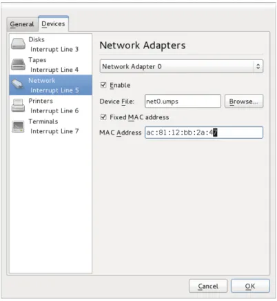
Associated with every installed device in a µMPS2 machine is a regular file on the host’s file system, called a device file. The precise role of the file depends on the type of device it is associated with; for simple peripherals, such as terminals and printers, it simply acts as log of the device’s input and output. For non-volatile memory— that is, disks and tapes—device files act as a persistent backing store, thus allowing devices to retain data even when not powered. Like basic machine parameters, device settings can be edited using the machine configuration dialog (see figure 3.3).
Figure 3.3: Device settings.
3.3.2 Byte Order in µMPS
Various computer architectures differ, among other things, in the adopted byte order scheme for native types (also commonly referred to as “endianness”). Endianness can have, in particular, important performance implications for computer emulation. If the host and emulated target endianness do not match, data needs to be converted back and forth between the two formats. To avoid this overhead, the µMPS processor always adopts the endianness of the host system.
Beside the emulator, endianness considerations are also of importance for the
3.4. Machine Control and Monitoring 19
basis of the input file. Thus, for example, the output file produced by the ELF to
µMPS .aout conversion utility will use the same byte order as the (ELF) input object
file.
3.4
Machine Control and Monitoring
In many respects, the µMPS2 emulator, together with its user interface, is an en-vironment that bears similarity to that of a typical user mode program debugger. Mainstream debuggers provide an environment which grants the user fine-grained control over the execution of a program, such as the ability to temporarily suspend the execution in response to certain events (e.g. breakpoints, signals). A debugger also allows easy inspection of the program’s state. In very much the same manner, the µMPS2 emulator offers a similar level of control over the execution of a virtual machine and allows inspection of the machine’s state. In the rest of this section, we describe these mechanisms in fair detail.
3.4.1 Startup and Shutdown
Whenever the emulator is provided with a machine configuration, the corresponding machine may or may not be in an initialized state (that is, “powered on”). When a user command is issued to start the machine, µMPS2 validates the active machine configuration and, if possible, starts machine emulation proper. By contrast, the machine may be powered off either as a result of a user action, or as a result of an
action initiated by the guest code.1
3.4.2 Execution Control
In the µMPS2 emulator, as in any useful debugging environment, methods are pro-vided to request the execution of the machine to temporarily stop at specific points in the program or as a result of particular verified conditions. Once the machine has been paused, it can be inspected and debugging related variables can be modified. Execution can be resumed either by stepping through single machine instructions at a time, or by allowing the emulator to continue normal execution indefinitely—that is, until the next event of interest is verified.
The emulator can temporarily suspend execution of the guest when conditions of certain kind are verified; we will refer to those as stop conditions. The following stop conditions are supported by µMPS2:
• User Requested Stops. At any point during execution, the user can issue a stop command.
• Breakpoints and Suspects. These are programmer-specified stop conditions whose semantics match their direct equivalents in conventional debuggers.
20 Chapter 3. The µMPS2 Emulator: A User’s View
• CPU Exceptions. The emulator can also be instructed to stop on hardware ex-ceptions from any emulated processor.
The various types of stop conditions can be globally enabled or disabled by the user, either via a pull-down menu or via a convenient “stop mask” pane located within the main window (refer to figure 3.1). In addition, breakpoints and suspects can be toggled on an entry-by-entry basis.
Execution Model
We have thus far informally described the debugging features of the µMPS2 emu-lator. To avoid possible confusion, we now proceed to describe in some detail the underlying execution model. For the most part, this amounts to giving precise se-mantics of the various execution states that can be associated with virtual processors and the machine as a whole.
An active (i.e., powered on) machine can at any time be in one of two execution states: running and stopped. A machine can be stopped either as a result of a user-initiated action, or because an event is triggered (by the guest code) that verifies one or more stop conditions.
A processor’s execution status denotes its operational condition, and its possible values form a refinement of the processor’s power states (see Section A.1.1):
• Halted. This state directly corresponds to the homonymous CPU power state; the execution state reads as halted if and only when the power state does. • Running. The processor is shown to be in a running state when it is in the power
state of the same name and the machine’s execution has not been paused. • Stopped. The status implies the machine’s execution has been suspended, and
the processor was previously in a running state (conversely, a stopped machine implies that a processor status cannot read running). If the machine is paused as a result of a stop condition that was triggered by executing an instruction on the CPU in question, the relevant information pertaining the cause is included in the status. Thus, a possible status entry may display, for instance
Stopped: Breakpoint(B3)
to indicate that the machine has been paused because a breakpoint (identified by B3) had been reached.
• Idle. Like halted, this state also corresponds directly to the power state of the same name.
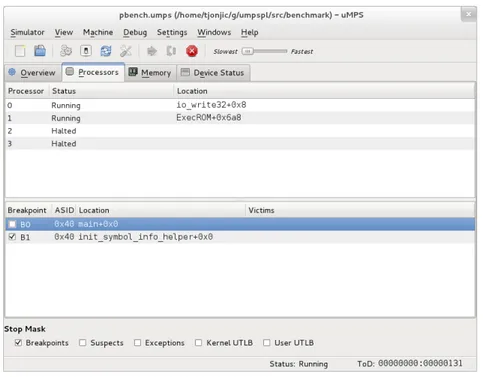
The execution status for all processors is displayed in the processor list pane (see figure 3.4), located in the upper half of the main window’s processors tab.
On any stop condition, the emulator suspends execution for the machine as a whole; in other words, the stopped machine execution state implies that none of the
3.4. Machine Control and Monitoring 21
Figure 3.4: The main window’s processor tab pane.
processors are in the running state.2 As already noted above, multiple events may
simultaneously cause the emulator to pause the execution of the machine.
3.4.3 Breakpoints and Suspects
As noted above, µMPS2 allows the user to define stopping points within a guest program. Readers will in all likelihood already be familiar with these notions from previous experience with traditional debuggers. Because of possible terminological friction, however, we nevertheless define the concepts precisely.
A breakpoint is a single, either physical or virtual, word-aligned address; the em-ulator is able to suspend machine execution when an instruction is fetched from the location pointed to by the address. Emulation is paused precisely before the instruc-tion in quesinstruc-tion is executed.
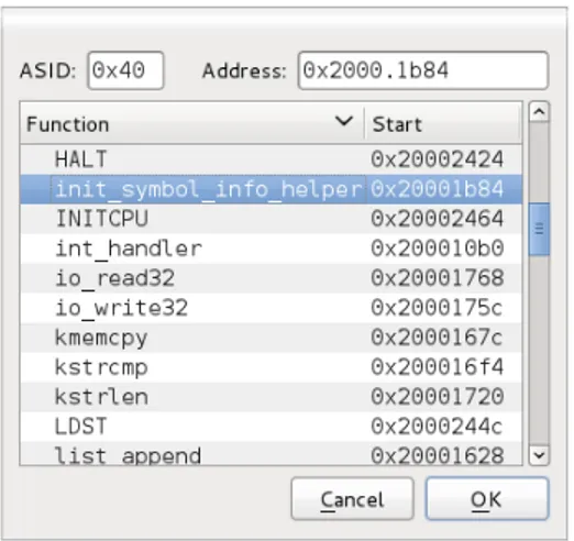
Breakpoints can be set via the breakpoint insertion dialog (see figure 3.5) or the code view (see Section 3.4.4). Each breakpoint can at any time be enabled or disabled, a task performed via the breakpoint list pane. Additionally, inserted breakpoints can be collectively disabled, using either a menu command or the convenient stop mask pane.
A suspect, which is specified by a range of consecutive word-aligned addresses,
2 Some user-mode debuggers support execution modes in which a subset of threads comprising
a multithreaded program are allowed to execute while other threads are stopped. µMPS2 does not support an analogous execution mode that would allow only a strict subset of CPUs to proceed with execution. While this feature is arguably useful for debugging multithreaded user-mode programs, it was dismissed as being overly unrealistic (and confusing) in our context.
22 Chapter 3. The µMPS2 Emulator: A User’s View
Figure 3.5: The breakpoint insertion dialog.
causes machine execution to be suspended on a read or write access to a memory location in the suspect’s range. There are three types of suspects: read, write, and read/write; each of these types has expected and obvious semantics (a read-only sus-pect, for example, will cause the emulator to stop execution only on loads—but not on stores—from the memory location in question). Like breakpoints, suspects can be toggled collectively or on an entry-by-entry basis.
Suspects and breakpoints can be associated with an address space identifier (ASID). This allows (simultaneous) debugging of code running with address trans-lation disabled (i.e. the kernel) and code running with address transtrans-lation enabled (i.e. user mode processes).
3.4.4 Examining Processor State
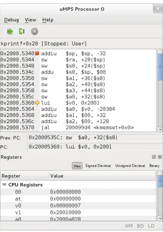
The µMPS2 architecture supports machines with up to sixteen processors. It is often desirable during the debugging process to examine the current state of one or more processors. By “state”, of course, we intend all the architecturally visible state. Without proper organization at the user interface level, the abundance of information could easily become overwhelming. The solution adopted by µMPS2 is a multi-window interface; each installed processor has an associated processor window, which can be shown or hidden at the user’s preference. An example is shown in figure 3.6.
In addition to the standard menu and toolbar, the CPU window comprises several elements, some of which are optional:
• The code view displays a code disassembly of the currently executing function. For convenience, the user can add and remove breakpoints on the shown loca-tions directly using the code view.
• The register view displays the value of general purpose registers, CP0 registers, along with some non-architectural register-like data (such as the “program counter”). The user is able to switch between hexadecimal, signed decimal,
3.4. Machine Control and Monitoring 23
Figure 3.6: The processor window. The code view—which forms the core and always-visible part of the window—is shown in the upper half. Breakpoints are repre-sented by suitable markers along the relative memory addresses; in the shown example, a breakpoint is set at the procedure’s entry point. In the lower part, a dockable CPU register view is present. The TLB display, another optional dockable pane, is not present.
unsigned decimal, and binary representations of these values. Register values can be modified by the user, and input is supported in each of the aforemen-tioned representations.
• The TLB view displays the contents of the translation lookaside buffer (TLB). As with CPU registers, TLB entries can be modified by the user.
3.4.5 Memory View
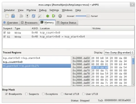
It is often desirable during a debugging session to inspect arbitrary memory con-tents. µMPS2 allows the user to define multiple address intervals, called traced re-gions, which can later be easily accessed in order to display the respective memory contents. The user interface elements of this facility are located in the memory tab of the application’s main window, as shown in figure 3.7. The memory tab also hosts the list of memory suspect ranges.
non-24 Chapter 3. The µMPS2 Emulator: A User’s View
Figure 3.7: The main window’s memory tab. The tab hosts the list of memory suspect ranges in the upper half, and the list and rendering of defined traced regions. A hexadecimal dump of the selected memory region is shown.
editable ASCII mode and an interactive “hex dump” mode that supports in-place editing of the memory contents. The former would typically be used for textual data, and the latter in any other case.
3.4.6 Device Monitoring
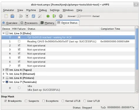
The last tab pane in the main window displays device status information, as shown in figure 3.8. Device information is organized into a tree, in which the top-level branches represent device types, and the leaves the respective devices. Since the various device types in µMPS2 provide a rather uniform memory-mapped register interface, a common display format was possible for all devices.
3.4.7 Terminals
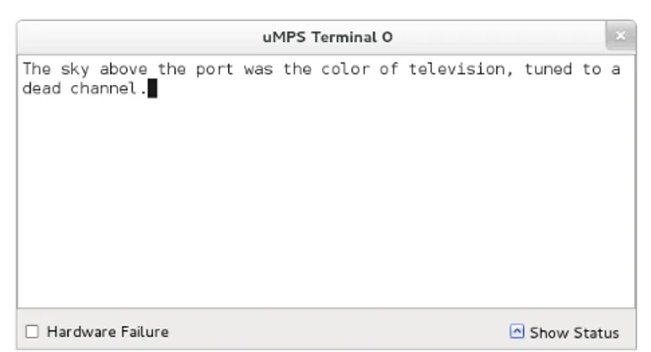
µMPS2 features a single human interface device—the terminal. The terminal window,
shown in figure 3.9, is the UI counterpart to terminal devices; in a sense, it is akin to terminal emulator packages common on modern desktop systems (parenthetically though, µMPS2 terminals do not share the complexity nor the feature set of real-world text terminals, such as VT100).
3.5. Programming for µMPS2 25
Figure 3.8: Device status view. Devices are grouped by type (or, equivalently, by interrupt line assignment) and each group can be expanded or collapsed according to preferences.
3.5
Programming for µMPS2
As has been already stressed, the inherent suitability of µMPS as a target platform for educational or experimental operating systems is a direct result of its streamlined machine architecture. Furthermore, because of its choice of instruction set architec-ture, it is readily supported by existing cross compilers. Thus, it can be claimed that development for µMPS is not substantially different from that of any other (bare-machine) platform, if only easier. There are a number of ways, however, in which
µMPS further simplifies this process for the beginner. In a nutshell, it achieves that by
including support for a simplified object file format, providing useful pre-built ROM images with code that implements a beginner-friendly exception handling scheme, and by supporting a much simplified boot process. This section is only meant to give a brief overview of the development process; the documentation mentioned at the end of the chapter covers the topic in detail.
3.5.1 ROM Images
The µMPS2 emulator requires the user to provide images for the bootstrap and exe-cution ROM, which are expected to supply vital low-level code. The bootstrap and execution ROM images are mapped to locations that coincide with the bootstrap and exception vectors, respectively. At machine reset time, processor 0 begins its instruction-cycle starting at location 0x1FC0.0000, which is contained in the
ad-26 Chapter 3. The µMPS2 Emulator: A User’s View
Figure 3.9: The terminal window. For convenience, optional device status informa-tion can be shown at the bottom.
dress range on which the bootstrap ROM is mapped to. Likewise, whenever a hard-ware exception is raised during normal system operation, control is transferred to location 0x0000.0080. At this address, located in the execution ROM range, ex-ception handling code is expected to be found.
Useful ROM images are included in the µMPS2 distribution that should suffice for most uses. The execution ROM, in particular, implements the two-phase excep-tion handling mechanism menexcep-tioned in chapter 2 and described in detail in [11]. Advanced users can, of course, fairly easily provide alternative implementations if the need arises.
3.5.2 The Toolchain
It is hardly worth pointing out that users are expected to program for µMPS2 in a high-level language. At this time, the most viable implementation language for
targeting µMPS2 is certainly C, with C++ perhaps being another plausible option.3
Being a conforming implementation of the MIPS-I ISA, µMPS2 is supported by un-modified MIPS cross-development toolchains—that is, compilers along with the as-sociated set of object file utilities. The toolchain that has been so far used by the project maintainers exclusively, and has been subject to extensive testing, is the GNU toolchain—formed by the GNU Compiler Collection and the GNU Binutils suite.
For completeness, we should also mention that it is conceivable that one may wish to use a standard C library for µMPS development, either for the kernel it-self or (more likely) for programs hosted under it. There are several lightweight C standard library implementations that one could with some effort adopt for µMPS development. One particularly popular choice on embedded systems in general is Newlib [19], which only requires a relatively small amount of platform-specific code.
3Depending on personal preferences, some features of C++, such as syntactic support for
single-dispatch polymorphism and generic programming, may be tempting enough for some programmers to select C++ as an implementation language for an operating systems kernel. On the downside, certain features of the language require the programmer to provide special run-time support when used in an unhosted environment. It is far from clear, then, whether the extra effort is offset by the benefits for simple projects.
3.6. Further References 27
3.5.3 Object File Formats
Virtually all fairly recent versions of GNU cross-development toolchains for MIPS
systems use the ELF object file4 format natively. This format, while having many
virtues, requires in general somewhat complex run-time support (i.e. loaders). For this reason, µMPS includes support for a greatly simplified format that comes in two variants, called .aout and .core, based on the much older UNIX a.out format. This format, while not as flexible as ELF, requires much simpler run-time support and should suffice for most uses. On the other hand, the ELF format may well be preferred for more ambitious projects due to its versatility (such as its ability to embed arbitrary metadata in a structured manner). The use of ELF (or any other format) is of course entirely possible, since the emulator is in no way linked to any notion of object file format. Ready to use boot loading code that is included with
µMPS2 only supports the .core variant of the .aout format, however.
3.5.4 Operating System Bootstrap
In many cases, it is advisable to enable users to start experimenting with the µMPS2 system by writing simple programs without requiring them to dwell into object file format details and boot loading code. There are two ways to achieve this in µMPS2. One option is to use the pre-built bootstrap ROM module tapeboot.rom.umps, which contains a simple boot loader; the program (e.g. operating system) is in this case expected to be located on the first tape device.
Another extremely convenient bootstrap option is to take advantage of the emu-lator’s ability to pre-load the executable into memory before machine startup. The
coreboot.rom.umps ROM module should be used in this case. In both cases the
program is expected to be in the .core format.
3.6
Further References
The official µMPS2 reference [11] contains a full description of the standard ROM services, the specification of the µMPS object file formats, and programming tips. A rather in-depth guide on some MIPS-specific aspects of the GNU toolchain, aimed specifically at µMPS2 users, is [20].
4By the term object file, we refer in general to relocatable object files, executables, and shared
Chapter 4
µMPS2 Emulator Internals
In this chapter we describe in reasonable detail the inner workings of the µMPS2 emulator. In most cases, the discussion is limited to key design choices and the general structure of the software; the source itself remains the authoritative reference for any finer detail.
4.1
Design Principles and Overall Structure
Before dwelling into any details about the emulator’s internals, we mention several core design goals that had a pervasive impact on its code base. First and foremost, the µMPS code base strives to be a convenient ground for experimentation and fur-ther extensions or improvements. Simplicity, elegance, and ease of maintenance of the resulting code, for instance, have often taken precedence over other qualities in the selection of solution alternatives for a given problem. In particular, the primary focus of the µMPS2 emulator is not uncompromising performance, as it is for emu-lators such as QEMU—aimed at running real-world operating systems and realistic workloads.
An important feature of the emulator is the complete independence of the core emulation code (the back-end) from user interface (front-end) code; the communication between the two takes place through a well-defined API. Thus, in spite of the fact that the sole user interface supported at the time of writing is a fully-fledged graphical one, it is entirely feasible that a command-line based interface may be supported in the future, for example.
In light of what was said above, we can group the modules comprising the
µMPS2 system into several categories. First, the emulation engine consists of
pro-cessor emulation code, various device models, as well as machine management and debugging support. A user interface is then provided via a series of modules that em-ploy the API exposed by the emulation engine; it consists of a multitude of classes which display machine state, as well as user interface counterparts to debugging-related facilities. Last, we find modules belonging to auxiliary standalone programs, such as the block device creation utility, or the µMPS .aout object file creation and
30 Chapter 4. µMPS2 Emulator Internals
inspection tools.
4.1.1 Signals, Slots, and the Observer Pattern
In the implementation of software systems of non-trivial complexity, there often arises a need for certain entities comprising the program (the observers) to be notified about particular events of interest related to another entity (the observable). What we vaguely refer to as “entities” are typically class instances, and the “events of interest” are changes in the object’s visible state; that, however, is certainly not a technical requirement. Moreover, this dependency between components should preferably be established without imposing a tight coupling between them. The archetypal example of this is to be found in user interface toolkit libraries, where changes in user interface elements are usually required to trigger an appropriate reaction from parts of the program expressing some domain-specific logic.
What is desirable, then, is to have a consistent and idiomatic way of expressing
the propagation of change in a program.1 Since considerable infrastructure is needed
to implement this pattern in a satisfactory manner, it is preferable to employ one of the many available libraries. While the terminology and metaphors vary across im-plementations, all the different APIs are centered around the basic abstract notions of signals and slots. Signals are representations of events that can be programmatically emitted. Each signal can be bound to multiple slots—specially designated functions or function-like objects that intercept the signal whenever it is emitted. Virtually all library implementations provide two main benefits over hand-maintained code:
• Boilerplate code is reduced to a minimum; for example, the infrastructure needed to maintain the list of observers for each given signal is provided by the library.
• Automatic tracking of object lifetime is provided by the library, thus avoiding the tedious task of manually unbinding signals from deallocated observers. In µMPS2 two such implementations are used. The emulation back-end employs the highly portable and lightweight libsigc++ [22] library. Within the front-end code, the Qt framework’s own signal/slot facility is leveraged, for better integration with other components of the framework.
4.1.2 Portability and the Choice of Implementation Language
The current µMPS2 project inherited its code base from µMPS, which in turn was— implementation-wise—an incremental evolution of the original MPS system. For MPS, C++ [23] had been chosen as the implementation language. It is arguable that C++, especially at the time, offered a very sound compromise between performance and high-level language features; since both of these requirements were (and still are) of uttermost importance for a program such as a computer system emulator,
4.1. Design Principles and Overall Structure 31
C++ was at the very least a justifiable choice. The µMPS2 project has retained C++ as the implementation language, and has gradually shifted from a pre-standard di-alect to the C++03 standard and a slightly more liberal use of language facilities and
the standard library.2 The current versions of all widely used C++ compilers fully
support this standard. The core emulator code depends on a small number of ex-ternal libraries—most notably, the Boost library—all of which are portable across all major platforms.
In addition to the dependencies inherited from the emulation back-end, the re-sulting application further depends on the Qt libraries, on which the user interface
in µMPS2 is built upon.3
Finally, we include a note on build automation, as it can be seen as a portability consideration. For any project of considerable size or dependency requirements, the use of a robust build automation system is likely to be vastly superior to more primitive solutions, such as hand-written Makefiles and ad-hoc shell scripts. µMPS2 currently uses the GNU build system, most notably GNU Automake and Autoconf. Despite some of its shortcomings—such as being almost inherently tied to Unix-like systems—the GNU build system (commonly referred to as the “Autotools”) has so far met the project’s requirements.
4.1.3 Source Tree Structure
In the rest of this chapter, various subsystems of the emulator are discussed. For ease of reference, a description of the source tree layout is given below:
build-aux
Auxiliary files pertaining to the build system.
examples
Self-contained example programs for µMPS2.
m4
GNU M4 macros, another part of the build system infrastructure.
src/base
Library of common utility classes and functions.
src/frontends/qmps
GUI emulator frontend.
2The experience with the project has been, however, a first hand confirmation of the daunting
complexity of the C++ language. This is both due to single language components in isolation (such as its complicated but nevertheless inflexible type system) and to their interoperability. The last is in many situations likely to lead to corner cases that are poorly understood by programmers or cause portability issues because of inconsistent support across different compilers. The programmer is thus often forced to adopt an austere discipline in the selection of language constructs and library facilities.
![Georges Güntert, Momenti salienti nella narrativa italiana fra Otto e Novecento, Franco Cesati Editore, Firenze 2020: [recensione]](data:image/gif;base64,R0lGODlhAQABAIAAAP///wAAACH5BAEAAAAALAAAAAABAAEAAAICRAEAOw==)