Abstract—In this paper, we theoretically and experimentally
investigate the performance of erbium-doped fiber amplifier (EDFA)-based WDM ring networks with free amplified spon-taneous emission (ASE) light recirculation. We show that, with proper network and amplifier design, the lasing light generated by free ASE recirculation within the looped network provides an effective gain clamping technique, ensuring limited signal power excursions under WDM channels add-drop operations. Considering a ring network composed of eight fiber sections and eight EDFAs, maximum signal power overshoots below 2.5 dB have been measured under23 24 WDM channels drop. Optical signal-to-noise ratio (OSNR) analysis and bit-error rate (BER) measurement at 10 Gb/s confirm acceptable performances and negligible penalties due to polarization effects and relative in-tensity noise transfer from laser light to WDM signals. We also propose and demonstrate a new link control technique which over-comes the main limiting factors of such networks, respectively, related to OSNR degradation, stability and survivability to fiber and EDFA breakages.
Index Terms—Erbium-doped fiber amplifiers (EDFAs), gain
clamping, transient effects, WDM optical networks.
I. INTRODUCTION
L
OW cost and effective amplifier power transient controls are becoming essential for future WDM metro-core net-work development. Although new amplification technologies, such as Raman [1] and semiconductor optical amplifiers [2] can provide remarkable performances in terms of gain bandwidth and flexibility, standard erbium-doped fiber amplifiers (EDFAs) are still the most attractive solution as the best tradeoff between cost end performances. When EDFAs are used in add/drop networks [3], or in presence of traffic bursts [4], signal power transients due to the variable input signal load, can cause seriousManuscript received July 5, 2004; revised November 17, 2004.
G. Sacchi, S. Sugliani, and A. Bogoni are with the Photonic Networks Na-tional Laboratory, Consorzio Nazionale Interuniversitario per le Telecomuni-cazioni (CNIT), 56124 Pisa, Italy.
F. Di Pasquale is with Scuola Superiore Sant’Anna di Studi Universitari e Perfezionamento, 56127 Pisa, Italy (e-mail: [email protected]).
R. Di Muro is with Marconi Corporation plc, New Century Park, CV3 1 HJ Coventry, U.K.
R. Magri and G. Bruno are with Marconi Communications, 56124 Genova, Italy.
F. Cavaliere is with Marconi Photonics Technology Research Center, 56124 Pisa, Italy.
Digital Object Identifier 10.1109/JLT.2005.843471
performance degradation, therefore gain control techniques must be used, which can be either electrical or all-optical.
In WDM ring networks, in which EDFAs are used to com-pensate the losses of both fiber spans and network elements, closed optical paths can be formed, giving rise to uncontrolled lasing oscillations which can impair network performances under WDM channels add-drop operations [5].
In this paper we demonstrate, by power transients and net-work performance analysis, that closed cycle lasing can be made stable and used to stabilize reconfigurable WDM net-works. Both theory and experiments confirm that an effective all-optical gain clamping technique for EDFA-based WDM ring networks, can be implemented, based on free amplified spontaneous emission (ASE) light recirculation along the ring. We show that proper network and amplifier design can make the system robust to WDM channels add-drop operations pro-viding, at the same time, a cost effective signal power transients control and acceptable optical signal-to-noise ratio (OSNR) performances.
However, although ASE light recirculation can ensure lim-ited power transient under WDM channels add-drop operations, avoiding complex and costly devices and algorithms, optical ring networks based on this gain clamping technique suffer from two main limiting factors.
The first one is related to OSNR degradation; in fact in order to make the network stable under add-drop operations, relatively high span losses between consecutive EDFA are required. It is quite difficult to ensure good network stability and high OSNR at the same time.
The second important limiting factor is that, in case of EDFA and/or fiber breakage, strong signal power excursions are ex-pected because of loss of the clamping mechanism, provided by ASE recirculation.
Here we propose and demonstrate a new link control tech-nique [6], which consists in injecting a laser beam at a given amplifier node of the ring network, and leave it free to circu-late in the loop [7]. Although suitable EDFA electronic control strategies can be implemented in order to deal with amplifier and/or fiber breakage, the insertion of this laser beam, being cen-tered around a wavelength where it is desired that a lasing peak is generated, provides at the same time great network robust-ness in terms of span loss variations, very limited signal power
the saturation fiber parameter [9] and erbium metastable life-time . The reservoir is defined as
(1)
where is the erbium concentration, A is the active fiber cross section, L is the erbium-doped fiber length, and
is the average metastable level population density , normalized to the erbium concentration . The reservoir dy-namics can be described by the following ordinary differential equation
(2) where is the Plank’s constant and indices k from 1 to M and j from to represent the discretized ASE light, represents the pump light and j from 1 to N the WDM signals;
is the frequency resolution and the factor 4 represents two polarization components for both forward and backward ASE light. The spontaneous emission factor in (2) can be expressed as [4]
(3) In (2)
(4) where is the active fiber effective area.
The time domain evolution of the WDM signals, ASE and pump lights at the amplifier output can be written as:
(5) where
(6)
multiple of the network round-trip time. In particular, the solu-tion is divided into a sequence of investigasolu-tion time windows equal to the round trip time. During the first investigation time window the ASE spectrum at the input of the first amplifier, is initialized to the previously computed steady-state condition. The ASE light at the output of the last amplifier in the ring network becomes the new initial value of the ASE spectrum at the input of the first amplifier for the following loop analysis. This numerical procedure works well as long as the round-trip time is long enough to allow steady-state conditions to be reached in each time window of the sequence; this condition is always satisfied in practical cases, considering fiber spool of several tens of km between two consecutive EDFAs.
As we will show in detail in the following sections, this model allows us for a deep understanding of the physical mech-anisms describing all-optical gain clamping in such looped optical networks.
III. EXPERIMENTALSETUP FOR AWORSTCASE
SCENARIOANALYSIS
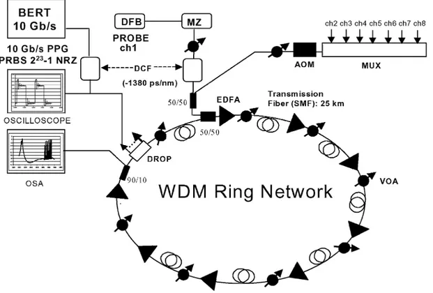
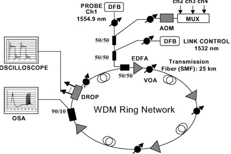
In this section we describe the experimental setup, shown in Fig. 1, which has been used for validating the dynamic model described in Section II; it reproduces a worst case scenario in term of transient effects, and can also be used for studying EDFA-based WDM ring network performances under different operation conditions [10].
Seven, high power, 100 GHz ITU spaced DFB lasers (from 1552.52 nm to 1557.36 nm) are multiplexed and switched on and off at low frequencies by an acouto-optic modu-lator (AOM), before being combined with a probe signal at 1551.72 nm. Note that in order to reproduce adding and dropping of channels, the power/channel of the seven loading signals is always chosen about 5 dB higher than the
probe power .
All WDM signals are then inserted into the ring, at the first EDFA input, and then propagated along the network before being extracted at the last EDFA output, through a fixed 8 chan-nels add-drop multiplexer which leaves the ASE light to freely circulate in the ring. All EDFAs in the network have a simple structure, without gain equalizing filters, and are operated at constant pump power (100 mW at 980 nm).
To fully investigate the clamping mechanism provided by ASE light recirculation, the modulation period of the AOM should be much longer than the network round trip time; in
Fig. 1. Experimental set-up representing a worst case scenario.
particular, with seven sections of 25 km standard SM fiber, as shown in Fig. 1, the network round trip time is about 875 s and a modulation frequency of 100 Hz (period: 5 ms) is low enough for the probe signal to reach staedy state conditions between consecutive WDM channels add and drop operations.
The setup shown in Fig. 1 allows us to measure the output spectrum, optical signal to noise ratio, the probe power tran-sients induced by add-drop operations and probe bit-error rate (BER) performances at 10 Gb/s. Note that two dispersion com-pensating fiber spools ( ps/nm) are introduced, respec-tively, at the transmitter and receiver side, to compensate almost exactly for the accumulated chromatic dispersion (
ps/nm). Variable optical attenuators (VOA) are used in each fiber span (25 km of standard SMF) and at the transmitter side in order to investigate network per-formances in different operation conditions such as varying the input power per channel and the span losses.
IV. VALIDATION OF THEMODEL
The theoretical model described in Section II has been first validated for a single EDFA under WDM channels add-drop op-erations. The EDFA structure is very simple, consisting in about 10 m of alumina-silicate erbium-doped fiber (peak absorption: 8.5 dB/m at 1532 nm), bidirectionally pumped at 980 nm by a total pump power of 100 mW coupled into the active fiber. The intrinsic saturation fiber parameter has been obtained by mea-suring the saturation pump power at 980 nm (0.5 mW) and using the equation:
(7)
where is the pump absorption at frequency and h is the Plank constant.
The erbium metastable lifetime is 10 ms and pump absorption coefficient at 980 nm is dB/m.
In order the validate the single EDFA dynamic model under WDM channels add-drop operation a simple experiment has been carried out in which seven 100 GHz ITU spaced WDM channels from 1549.32 to 1554.13 nm, simulating a full ampli-fier load of 23 channels, are first modulated at low frequency by an AOM in order to reproduce WDM channels add-drop, and then combined with a CW probe signal at 1532.68 nm and coupled at the EDFA input. The probe transient behavior at the EDFA output is observed by filtering the signal at 1532.68 nm and using an oscilloscope.
The computed and measured probe rise and fall times, defined as the transition times between 10% and 90% of the change in optical power, respectively, induced by WDM channels drop and add operations, are shown in Fig. 2 versus total amplifier input signal power. Good agreement between theory and experiment can be noted; add transients are faster than drop transients and while decreases, increases with the total input signal power. The measured excursion level between full amplifier load condition (24 WDM channels) and probe channel only, is about 13 dB, well in agreement with the-oretical predictions. Note that the single EDFA dynamic model well predicts experimental results for other probe wavelengths as well.
The model has then been validated in steady-state conditions considering EDFA-based WDM ring networks with ASE light recirculation (the experimental setup is shown in Fig. 1).
Fig. 2. Comparison between measured and computed rise and fall times.
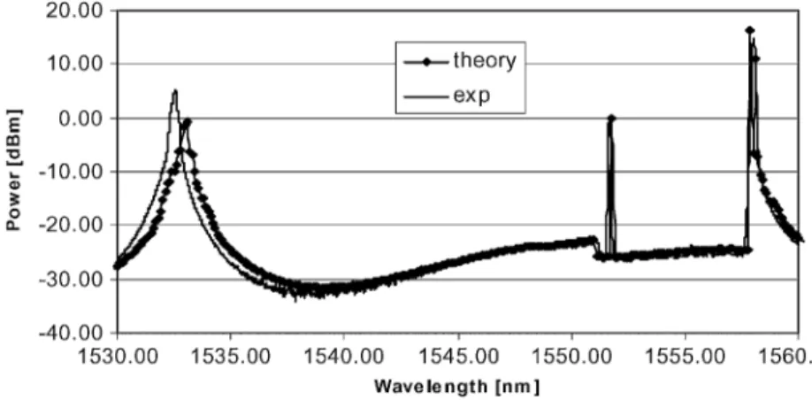
Fig. 3. Computed and measured output spectra from the last EDFA with span loss of 20 dB (82 20 dB).
Fig. 4. Computed and measured output spectra from the last EDFA with span loss of 18.5 dB (82 18.5 dB).
Figs. 3 and 4 compare the spectra at the last EDFA output with only probe channel at 1551.72 nm and two different span losses (respectively, 8 20 dB and 8 18.5 dB).
Although the theoretical model can not predict double gain peaking at around 1532 nm, due to polarization effects [11] which are not included in the theory, good agreement can be observed between theoretical predictions and experimental re-sults concerning ASE spectra distribution, output signal power, OSNR and gain peaking wavelength. Note that with shorter span losses (18.5 dB) gain peaking, due to ASE light recirculation in the ring, is competing between 1532 and 1560 nm, as clearly shown in Fig. 4.
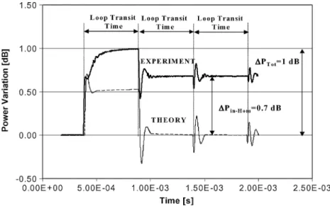
Finally, the dynamic model has been validated under add-drop operations, considering for the sake of simplicity only four fiber sections (25 km each) and four EDFAs. Fig. 5 compares the measured and computed probe transient behavior at the last EDFA output with a span loss of 20 dB. To reproduce adding and dropping of WDM channels the probe power at the first EDFA input is dBm and the input power for the seven channels, simulating the full network load, is dBm/ch. From these results we can notice a maximum probe power overshoot of about 1 dB, which is very small if compared with the strong power transient which would be expected in such a long EDFA chain without any gain control.
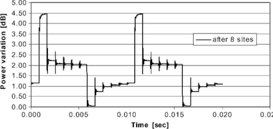
Fig. 5. Measured and computed probe transient behavior after 42 20 dB dropping 23=24 Channels.
Also note that after each loop transit time ( s) the lasing ligth, recirculating along the ring, clamps the gain with typical probe power transients induced by the lasing relaxation oscillations. The clamping mechanism, provided by the ASE light recirculation, is only partially effective and the measured steady-state probe power levels with full channels load and only probe signal differ from the theoretical predictions ( and in Fig. 5 are, respectively, defined as the maximum probe power overshoot and the staedy-state probe power difference between the two conditions of full channels load and only probe signal).
These discrepancies between theory and experiment are mainly due to spectral hole burning and inhomogeneous gain [12] which hide the probe transients due to laser relaxation oscillations induced by the WDM channels drop. Note however that the comparisons shown in Fig. 5 confirm the presence of very limited probe power overshoots induced by WDM channels drop operations.
Although the model predictions are optimistic in terms of gain clamping effectiveness, with same steady-state probe power levels with and without loading channels, they are however very effective in designing EDFA-based WDM ring networks with ASE light recirculation, and provide important information for amplifier and network structure optimization.
V. NETWORKPERFORMANCES
In this section we first describe the physical mechanisms gov-erning gain clamping in EDFA-based WDM ring networks with ASE light recirculation, and then we investigate network per-formances in terms of OSNR, relative intensity noise (RIN) transfer from lasing light to WDM signals, polarization effects and BER characteristics at 10 Gb/s.
We have studied the probe power transients at the last EDFA output, reproducing WDM channels add-drop opera-tions, as a function of the input power per channel at the first EDFA input. The span loss is 20 dB, high enough to ensure stable gain peaking at around 1532 nm, that is far enough from the WDM signal band, which would be from about 1542 to
1561 nm with 24, 100-GHz spaced channels. Note that, for a given EDFA structure and input power per channel, the span loss must be optimized in order to ensure the best compromise between good OSNR performances and lasing stability at around 1532 nm, under full WDM channels add-drop oper-ations. As we will show in details in the following sections, EDFA-based WDM ring networks self-stabiled by ASE light recirculation can achieve this best compromise considering quite high span losses, with a consequent degradation in the OSNR and network performances. In Section VI, we will point out that a very effective link control technique can be imple-mented, forcing a stable lasing action outside the WDM signal bandwidth without requiring high span losses; this technique provides better OSNR performances, ensuring at the same time good network stability and survivability.
Considering that the gain of the ring is equal to 1 at the gain peaking wavelength and less than 1 within the signal bandwidth, the maximum difference in the ring gain, , between gain peaking wavelength and WDM channel wavelengths, provides an important parameter for network and amplifier optimization. In particular while small values (less than 1 dB) reduces the WDM signal power losses in each span along the ring net-work ensuring good OSNR performances, higher values (greater than 1 dB) provide high network stability keeping the gain peaking wavelength steady in the position selected far from the channels. An optimum value has been identified to be about 1 dB.
Also note that introducing high-pass gain flattening filters within each EDFA allows one to force stable gain peaking at wavelengths close to the signal band, reducing at the same time the values and consequently ensuring good OSNR per-formances as well as network stability. In addition, the com-bined use of high-pass gain flattening filters and link control techniques can provide great network stability with lower span losses further improving the OSNR performances.
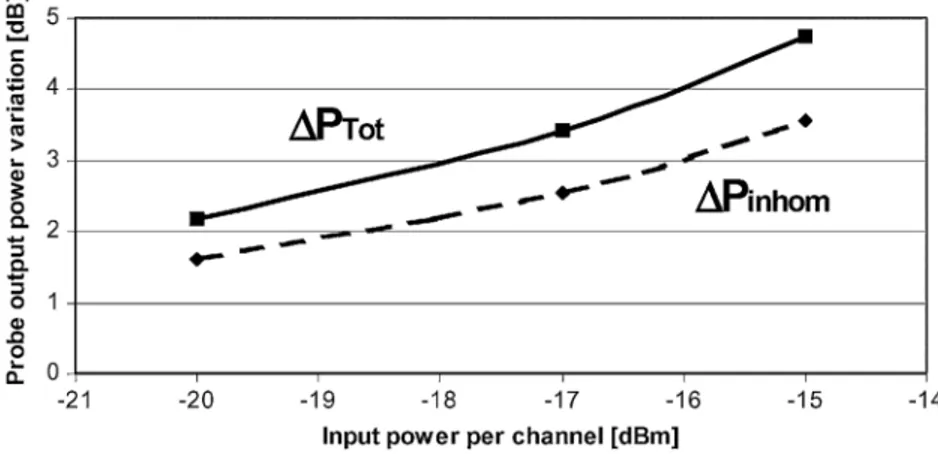
Fig. 6 describes the measured maximum probe power overshoot and the steady-state power difference , versus input power per channel at the first EDFA input, considering eight EDFAs and seven sections of
Fig. 6. Maximum probe output power overshoot after 82 20 dB versus input signal power per channel.
Fig. 7. Measured probe output power dynamic behavior after 82 20 dB with 015 dBm/ch.
25 km standard SM fiber (8 20 dB). Note that both
and grow with the input power per channel. This is due to the fact that the more the lasing light is predominant, compared to the total signal power, the more the clamping mechanism, provided by ASE light recirculation, is effective. As an example, Fig. 7 reports the probe power transient be-havior at the last EDFA output with input power per channel of dB/ch (the corresponding total input power is about dBm). Two different periodicities can be observed in the probe transient behavior, respectively, related to the clamping mechanism provided by ASE light recirculation, which fol-lows the loop transit time, and to WDM channels add-drop operations which are simulated using an AOM with a given modulation rate.
Note that the measured transient effects shown in Figs. 7 and 8 do not show probe power over- and undershoots, induced by WDM channels drop and add operations typical of EDFA cas-cades; this is due to the presence of inhomogeneous effects and the large time scale used in the plots in order to show how
steady-state conditions are reached between consecutive WDM channels add and drop operations.
We have, however, experimentally verified and confirmed by theory in Fig. 5, the presence of very limited power transients induced by add-drop operations when the network is self-stabi-lized by ASE light recirculation.
We have then investigated how transient effects depend on span losses. Fig. 8 shows the probe power transient at the last EDFA output, with dBm/ch and span loss of 18 dB. From this figure and the output spectra at the last EDFA output with only probe channel, shown in Fig. 9, we can see that gain peaking is now competing between 1532 and 1560 nm. This feature reduces spectral hole burning and inhomogenous effects, giving rise to lower steady-state power difference
.
Although short span losses improve the OSNR performance, they are not at all optimal in terms of network stability as the gain peaking wavelength can move, depending on the actual net-work load.
Fig. 8. Measured probe output power dynamic behavior after 82 18 dB with 017 dBm/ch.
Fig. 9. Measured output spectrum after 82 18 dB with probe channel at 017 dBm/ch.
TABLE I
MEASUREDOSNR WITH82 20 dB SPANLOSS AND017 dBm/ch
In the following section we will describe a new link control technique which allows one to use short span losses, ensuring at the same time improved OSNR performances, great network ro-bustness in terms of span loss variations and very limited power transients.
The network optical signal-to-noise ratio (SNR) perfor-mances have been experimentally investigated, showing that WDM channels in the lower wavelength region of the signal bandwidth experience poor OSNR performances.
Table I reports the measured OSNR over 0.1 nm resolution bandwidth after 8 20 dB transmission along the ring network (an additional channel has been added at 1542 nm). The OSNR over 0.1 nm resolution bandwidth is about 17 dB at the lower wavelength 1542 nm, and greater than 24 dB above 1555 nm.
Note that the EDFAs used in the experiments have not been optimized for particular application considered in this work; better OSNR performances can be achieved by amplifier opti-mization in terms of gain profile and flatness.
Fig. 10. Comparison between measured probe RIN with open and closed loop.
The maximum output OSNR variations, induced by polar-ization dependent effects, have been measured to be less than 0.7 dB.
Also the probe relative intensity noise has been measured and compared with open and closed ring, at the same OSNR value: no penalties have been observed due to RIN transfer from laser light to signals, as can be observed in Fig. 10. This confirms that the transfer of noise into the signal channels is inefficient due to the slow EDFA dynamic [3].
However, to exclude possible potential transmission penal-ties, related to both probe power transients and noise transfer from lasing light to WDM channels, we have performed BER measurement at 10 Gb/s.
The probe signal has been externally modulated at 10 Gb/s (PRBS , NRZ format) and BER measurements versus received optical power and OSNR have been performed.
Fig. 11. BER versus received optical power in back-to-back, with 82 20 dB span open loop and with 8 2 20 dB span closed ring.
Fig. 12. BER versus average OSNR in back-to-back (noise loading) and with closed loop (82 20 dB).
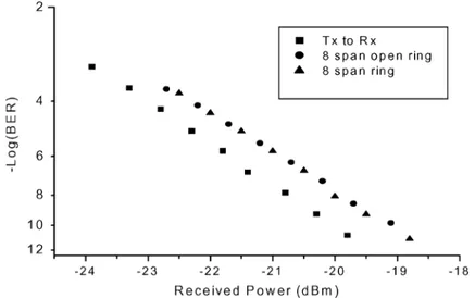
Fig. 11 reports the probe BER performances versus received power in back-to-back condition and with open and closed ring at the same OSNR value (23 dB). Note that BER performance in case of closed ring has been measured under WDM channels add-drop operations. No penalties have been observed due to the presence of ASE light recirculation.
The probe BER has also been measured versus OSNR values, in back-to-back condition (receiver characterization by noise loading) and with closed ring; the results, shown in Fig. 12 con-firms that no transmission penalties have been observed under add-drop operations.
Note that as all EDFAs in the network are operated at con-stant pump power, without electronic output power control, we have not observed any chaotic oscillation due to lasing effects in closed cycles, as experimentally shown in [13], where insta-bilities were likely induced by electronically controlled channel power equalizers. However, the results shown in [13] suggest
that, in order to avoid resonances related to the round-trip net-work transit time and consequent potential chaotic oscillations, care must be taken in introducing electronically controlled com-ponents in EDFA-based WDM ring networks with ASE light recirculation.
VI. LINKCONTROL ANDNETWORKSURVIVABILITY
In this section we investigate how link control techniques [6], [7] can be used in EDFA-based WDM ring networks with ASE light recirculation, in order to provide network robustness in terms of span loss variations, limited power transients, improved OSNR performance and, at the same time, high network surviv-ability in case of fiber or EDFA breakage.
We propose to inject a laser beam at a given amplifier node of the ring network, and leave it free to circulate in the loop.
Fig. 13 shows the experimental setup we have used to inves-tigate the proposed link control technique.
Fig. 13. Experimental setup for EDFA-based WDM ring network with ASE light recirculation and link control.
Fig. 14. Output spectra without link control.
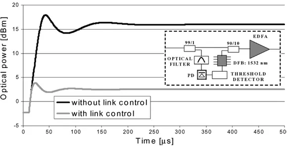
For the sake of simplicity, only four sections of 25 km stan-dard SM fiber and four EDFAs, operating at constant pump power (100 mW at 980 nm) were used. Three high power chan-nels are multiplexed and switched on and off at 100 Hz, by an acoustooptic modulator, to simulate adding and dropping of WDM channels, before being combined with a probe signal at 1554.9 nm. The probe dynamic behavior was observed after propagation along the entire looped network, with and without link control at 1532 nm, provided by a DFB laser which is also coupled into the network at the first EDFA input. Note that both link control and ASE light are free to circulate in the loop, while the three loading channels and probe signal are ex-tracted at the last EDFA output by a fixed four channel add-drop multiplexer.
Figs. 14 and 15 show the output spectra with full network load and single probe channel at dBm, respectively, with and without link control. The network span budget (4 19 dB) is such that, without link control, gain peaking can form within the WDM signal band, depending on the actual network load.
On the other hand, with link control, gain peaking is stable at 1532 nm. Note that the relative low loss of each span (19 dB) is advantageous in terms of OSNR performance but is not at all
op-timal in terms of dynamic behavior and network stability. Fig. 16 compares the probe transient behavior at the last EDFA output, with and without link control; larger power transients are present in the network only based on ASE light recirculation, and higher span losses would be required in this case, in order to ensure steady operation conditions, avoiding gain peaking competition at different wavelengths. Satisfying this requirement would en-sure stability of the ring.
It can also be noted that the link at 1532 nm avoids for-mation of a double ASE peak at around 1532 nm, providing higher robustness to polarization dependent effects. The use of link control techniques also allows one to perform, with lim-ited additional cost, a node amplifier structure which can guar-antee network survivability. Basically, each amplifier node can be equipped with a DFB laser which can be activated in case of network failure, caused by fiber or EDFA break. As shown in the inset of Fig. 17, a network failure can be easily detected in each node by splitting a small fraction of the total power at the EDFA input, and recognizing the presence of lasing light at around 1532 nm within the loop. If the lasing light falls below a given threshold, the DFB laser is switched on. Note that with a 2-nm filter bandwidth in the detection scheme, and with an amplifier design which ensures a total lasing light 3 dB above the total power of all WDM channels in normal operation con-ditions (i.e., with ASE light recirculation), the power difference between lasing light in normal operation and ASE light falling within the filter bandwidth in case of fiber or EDFA break, is always greater than 10 dB; this ensures an easy threshold selec-tion in the detecselec-tion circuit.
We have investigated this network scenario using the experi-mentally validated dynamic model previously described, which includes both ASE light recirculation and link control in EDFA-based WDM ring networks. Fig. 17 compares the computed probe transient effects, respectively, with and without network survivability scheme, at the last amplifier output of a ring net-work, composed of eight sections of 25-km SM fibers and eight EDFA.
Fig. 15. Output spectra with link control.
Fig. 16. Probe transient behavior with and without link control.
Fig. 17. Computed probe power transient at the last EDFA output following a fiber break, with and without link control for network survivability (the inset shows the detection scheme for network failure).
In conclusion, we have theoretically and experimentally investigated the performances of EDFA-based WDM ring network in which gain clamping is automatically achieved by free ASE light recirculation. We have shown that a proper network and amplifier design makes these networks robust to WDM channels add-drop operations, greatly simplifying network management and control. No transmission penalties, due to ASE recirculation have been experimentally observed. A new link control technique for EDFA-based WDM ring networks with ASE light recirculation has also been proposed and demonstrated; it provides great network robustness in terms of span loss variations, very limited power transients and improved OSNR performance. Moreover, this link control can also be exploited to guarantee high network survivability in case of fiber or EDFA breakage.
ACKNOWLEDGMENT
The authors would like to acknowledge P. Ghiggino for helpful discussions and suggestions.
REFERENCES
[1] M. Islam, Raman Amplifiers for Telecommunications 1, Physical Princi-ples and Raman Amplifiers for Telecommunications 2, Sub-Systems and Systems. New York: Springer-Verlag, 2003.
[2] P. Iannone and K. Reichmann, “In-service up-grade of an amplified 130-km metro CWDM transmission systems using single LOA with 140 nm bandwidth,” in OFC, Atlanta, GA, 2003. paper ThQ3. [3] Y. Sun, A. K. Srivastava, J. L. Zyskind, J. W. Sulhoff, T. A. Strasser, C.
Wolf, and J. R. Pedrazzani, “Signal power variations in optically ampli-fied WDM ring networks,” in ECOC, 1997, pp. 135–137.
[4] M. Karasek, A. Bononi, L. R. Rusch, and M. Menif, “Gain stabi-lization in gain clamped EDFA cascades fed by WDM burst-mode packet traffic,” J. Lightw. Technol., vol. 18, no. 3, pp. 308–313, Mar. 2000.
[5] W. Xin, G. K. Chang, B. W. Meagher, S. J. B. Yoo, J. L. Jackel, J. C. Young, H. Dai, and G. Ellinas, “Chaotic lasing effect in a closed cycle in transparent wavelength division multiplexed networks,” in OFC, 1999, pp. 246–248. paper TuR1-1.
[6] A. K. Srivastava, J. L. Zyskind, Y. Sun, J. Ellson, G. Newsome, R. W. Tkach, A. R. Chraplyvy, J. W. Sulhoff, T. A. Strasser, C. Wolf, and J. R. Pedrazzani, “Fast-link control protection of surviving channels in mul-tiwavelength optical networks,” IEEE Photon. Technol. Lett., vol. 9, no. 12, pp. 1667–1669, Dec. 1997.
[7] G. Sacchi, S. Sugliani, A. Bogoni, A. D’Errico, F. Di Pasquale, R. Di Muro, R. Magri, G. Bruno, and F. Cavaliere, “Link control and surviv-ability in EDFA based WDM ring networks with ASE light re-circula-tion,” in ECOC, Stokolm, Sweden, 2004. paper We4.P.082.
[8] A. Bononi and L. A. Rusch, “Doped-fiber amplifier dynamics: A system perspective,” J. Lightw. Technol., vol. 16, no. 5, pp. 945–956, May 1998.
[13] P. Kim, S. Bae, J. Kim, H. Choi, S. J. Ahn, H. G. Woo, and N. Park, “Analysis of the network oscillations in the amplified WDM ring net-work—Dependency on the channel power equalizer speed and network span length,” in OFC, 2000, pp. 59–61. paper ThD6-1.
G. Sacchi was born in Milan, Italy, in 1949. He
received the physics degree from the University of Milan, Milan, Italy, in 1979.
From 1980 to 1997, he worked for Italtel, Milan, Italy, as a Photonic Components Manager. From 1997 to 2000, he was an Optical Amplifier Designer with Pirelli Cavi, Milan, Italy. From 2000 to 2002, he was a Senior Researcher with Cisco Photonics, Monza, Italy. Since 2002, he has been a Researcher at Con-sorzio Nazionale Interuniversitario per le Telecomu-nicazioni (CNIT), Pisa, Italy. He has filed ten inter-national patents, and he is the author and coauthor of more than 20 scientific journal and conference papers in the area of optical amplifiers and optical com-munications systems. His research interests are in the area of optical amplifiers and fiber-optic transmissions.
S. Sugliani was born in Bergamo, Italy, in 1972.
He received the materials engineering degree and the Master’s degree in optical systems and networks from the Politecnico di Milano, Milan, Italy, in 1999 and 2001, respectively.
Since 2002, he has been a Research Assistant with the Photonic Networks National Laboratory, Consorzio Nazionale Interuniversitario per le Tele-comunicazioni (CNIT), Pisa, Italy. His current research interests include optical amplification and fiber-optic systems.
A. Bogoni was born in Mantova, Italy, in 1972. She
received the Dr.Ing. degree in electronics engineering and the Ph.D. degree from the University of Parma, Parma, Italy, in 1997 and 2004, respectively.
From 1998 to 1999, she was grantee of Marconi S.p.a. at the University of Parma in the Optic Com-munications Laboratory. Since 2000, she has been a Researcher at the Consorzio Nazionale Interuniver-sitario per le Telecomunicazioni (CNIT), Pisa, Italy. From 2000 to 2001, she worked in the Parma univer-sity laboratory, and since 2002, she has been a Senior Researcher at the National Photonic Networks National Laboratory, CNIT. Her research interests are in the area of fiber-optic transmissions.
filed 15 international patents, and he is the author and coauthor of more than 60 scientific journal and conference papers in the area of optical amplifiers, optical communications systems, and liquid-crystal displays.
R. Di Muro received the first-class honors degree
in electronics engineering from the University of Bologna, Bologna, Italy, in 1992. He received the Ph.D. degree from the University of Parma, Parma, Italy, in 1996 working on the analysis of nonlinear optics effects in components and optical devices. He is currently working toward an evening Executive Master’s in Business Administration (EMBA) at Warwick University, Warwick, U.K.
He taught high-level electronics and math at the University of Parma for more than one year. In 1996, he joined the University College London, London, U.K., where he worked on praseodimium-doped fiber amplifiers (PDFAs) and analysis of four-wave mixing in wavelength-division multiplexing (WDM) operating at 1300 nm. From 1996 to 1997, he was with the Ecole Nationale Supirieure des Tilicom-munications—Telecom Paris, France, where he worked on soliton systems in optical communication at 1550 nm for a high bit rate. In 1997, he joined the Advanced Technology Centre in Nortel plc, Harlow, Essex, U.K., where he worked on the design and characterization of an extended band amplifier. In 1999, he was an Amplifier Design and Product Engineer in the optoelectronic manufacturing division of Nortel Networks, Paignton, Devon, U.K. In 2000, he rejoined the Amplifier Group of Nortel Networks, Harlow, Essex, U.K., as a Leader in system propagation and amplifiers research for new applications such as short-wavelength bands. Since 2001, he has been a Photonic Strategist with Marconi Corporation plc, Coventry, U.K. He collaborates with European universities for long-term research. He has published 30 papers in conferences and technical publications and has submitted 11 patents in the area of commu-nications and amplification.
In 2000, he joined the Transmission Modeling and System Design Group in Marconi Communications, Optical Networks, Genova, Italy, where he served as a Modeling Engineer, taking part in the development and deployment of the wavelength-division-mul-tiplexing (WDM) long-haul product line. He is currently working on the modeling and network planning activity for the new generation of metro systems. His research interests include numerical modeling and simulation and network design problems in optical networks.
F. Cavaliere was born in Cosenza, Italy, in 1970. He
received the Dr.Ing. degree in telecommunications engineering from the University of Pisa, Pisa, Italy, in 1996.
Since 1998, he has worked for Marconi Corpo-ration plc. He is currently a Senior Engineer of the Transmission and Network Modeling Team at the Marconi Photonics Technology Research Center, Pisa, Italy. His research interests are in the design and modeling of wavelength-division-multiplexing (WDM) optical communication systems.