EU OFFICE BUILDINGS
BY
VINCENZO COSTANZO
A thesis submitted to the University of Catania in fulfilment of the requirements
for the degree of Doctor of Philosophy in Energetics (XXVIII Cycle)
University of Catania
Academic year 2015-2016
Cool materials are characterized by having a high solar reflectance r – which is able to reduce heat gains during daytime - and a high thermal emissivity ε that enables them to dissipate the heat absorbed throughout the day during night.
Despite the concept of cool roofs - i.e. the application of cool materials to roof surfaces - is well known in US since 1990s, many studies focused on their performance in both residential and commercial sectors under various climatic conditions for US countries, while only a few case studies are analyzed in EU countries.
The present thesis work aims at analyzing the thermal benefits due to their application to existing office buildings located in EU countries. Indeed, due to their weight in the existing buildings stock, as well as the very low rate of new buildings construction, the retrofit of office buildings is a topic of great concern worldwide.
After an in-depth characterization of the existing buildings stock in the EU, the thesis gives an insight into roof energy balance due to different technological solutions, showing in which cases and to what extent cool roofs are preferable.
A detailed description of the physical properties of cool materials and their availability on the market provides a solid background for the parametric analysis carried out by means of detailed numerical models that aims at evaluating cool roofs performance for various climates and office buildings configurations.
With the help of dynamic simulations, the thermal behavior of representative office buildings of the existing EU buildings stock is assessed in terms of thermal comfort and energy needs for air conditioning. The results, which consider several variations of building features that may affect the resulting energy balance, show how cool roofs are an effective strategy for reducing overheating occurrences and thus improving thermal comfort in any climate. On the other hand, potential heating penalties due to a reduction in the heat fluxes passing through the roof are taken into account, as well as the aging process of cool materials.
Finally, an economic analysis of the best performing models shows the boundaries for their economic convenience.
Abstract
iNomenclature
ivList of figures
viList of tables
ix1. Introduction 1
1.1 Towards nearly (or net) Zero Energy Buildings 1
1.2 EU buildings stock 6
1.3 Characteristics of the Office Buildings sector in EU-27 countries 10
1.4 Typical refurbishing actions for office buildings 15
1.5 Research topic and significance of the study 18
1.6 References of the chapter 19
2. Roof technologies and their energy behavior 22
2.1 General overview of Cool Roofs (CR) 22
2.2 General overview of Green Roofs (GR) 28
2.3 General overview of ventilated roofs (VR) 33
2.4 References of the chapter 39
3. Cool Roofs: state of the art 42
3.1 Optical properties 42
3.2 Cool materials 46
3.6 References of the chapter 68
4. Discovering the potential for Cool Roofs applicability: methodology 72
4.1 A “typical” office building model for EU countries 72
4.2 Simulation assumptions and parameters description 76
4.3 Climate analysis 79
4.4 Thermal comfort assessment: Operative Temperature and Intensity of Thermal Discomfort Index (ITD) 85
4.5 Energy needs assessment: Primary Energy (PE) consumption 88
4.6 References of the chapter 90
5. Year-round assessment: dynamic simulations 93
5.1 Thermal comfort and reduction of overheating occurrences 93
5.1.1 Operative temperature distribution over a typical summer month 94
5.1.2 ITD Index calculation 102
5.2 Energy needs and Primary Energy consumption 107
5.3 Economic analysis 113
6. Conclusions 116
APPENDIX I -
thermal characteristics of the existing EU office buildings stock 119Variables
A solar absorptance
COP Coefficient Of Performance EER Energy Efficiency Ratio
G solar spectral distribution /W m-2 nm-1) hc convective heat transfer coefficient (W m-2 K-1)
H heat flux (W)
I global horizontal solar irradiance (W m-2) ITD Intensity of Thermal Discomfort Index (°C h) K thermal conductivity (W m-1 K-1)
PE Primary Energy (MWh) PER Primary Energy Ratio q specific heat flux (W m-2) Q energy needs (Wh) r solar reflectance
R thermal resistance (m2 K W-1) RWR Roof to Walls Ratio
SRI Solar Reflectance Index T temperature (°C) U thermal transmittance (W m-2 K-1) Greek letters α thermal diffusivity (m2 s-1) ɛ thermal emissivity λ wavelength (nm) σ Stefan-Boltzmann constant (W m-2 K-4) τ time (s) ϕ relative humidity
g ground i indoor ir infrared lim limit max maximum min minimum o outdoor op operative s summer so outer surface sol solar w winter
Chapter 1
FIGURE 1.1: Graph representing the NZEB balance concept [4] FIGURE 1.2: Connections between buildings and energy grids [4] FIGURE 1.3: WWF headquarters in Zeist [Internet]
FIGURE 1.4: Pixel building in Melbourne [Internet]
FIGURE 1.5: EU Countries considered within BPIE survey together with population and floor distribution breakdown [7] FIGURE 1.6: Breakdown of the floor space typology (on the left) and age categorization (on the right) in Europe [7] FIGURE 1.7: Final energy use in the residential sector [7]
FIGURE 1.8: Final energy use in the non-residential sector [7]
FIGURE 1.9: Share of total energy use for the non-residential sector [7] FIGURE 1.10: Age construction breakdown for EU-27 countries [9] FIGURE 1.11: Office building 1 [9]
FIGURE 1.12: Office building 2 [9] FIGURE 1.13: Office building 3 [9]
FIGURE 1.14: Relationship between refurbishment scope and ability to influence carbon emissions [10] FIGURE 1.15: Example of double skin glass façade (a,c) and green façade (b) [15]
Chapter 2
FIGURE 2.1: View of cool roofs in Honolulu, Hawaii [Internet]
FIGURE 2.2: Peak heat gains (kW) per 100 m2 of a flat roof as a function of different combinations of Asol, E and R values [3]
FIGURE 2.3: Daily average cooling loads per 100 m2 of a flat roof as a function of different combinations of Asol, E and R values [3]
FIGURE 2.4: Variations in albedo for different exposure time for various flat roofs in California [5]
FIGURE 2.5: Difference between roof outer surface temperature and outdoor temperature as a function of hc [7]
FIGURE 2.6: Heat flux incoming through the roof as a function of hc [7]
FIGURE 2.7: View of green roofs in Stuttgart, Germany [Internet]
FIGURE 2.8: In situ thermal transmittance assessment for various green roof solutions [9]
FIGURE 2.9: Energy balance for a green roof, including latent heat flux (L), sensible heat flux G, shortwave (I) and longwave radiation (LW) [14]
FIGURE 2.10: Results of the sensitivity analysis of the EcoRoof routine on predicted thermal gain [19] FIGURE 2.11: Schematic representation of flat (top, [20]) and pitched (bottom, [21]) ventilated roofs FIGURE 2.12: Comparison of upper and lower roof surface temperatures [20]
FIGURE 3.1: Solar spectral irradiances according to ASTM G173-3 and AM1GH spectra [Author]
FIGURE 3.2: Typical cool roofs solutions: single ply membranes and modified bitumen in the first row, coatings in the second row and tiles and shingles in the last row [Internet]
FIGURE 3.3: Surface temperature reached by standard (bottom row) and cool (upper row) prototypical tiles developed by Levinson et al. [13]
FIGURE 3.4: Cool clay tile (on the left) and original clay tile appearances [14]
FIGURE 3.5: Reflectivity spectrum of coated fire clay tiles for increasing number of coating layers [14] FIGURE 3.6: Cool pavements (on the left) and cool asphalt (on the right) [Internet]
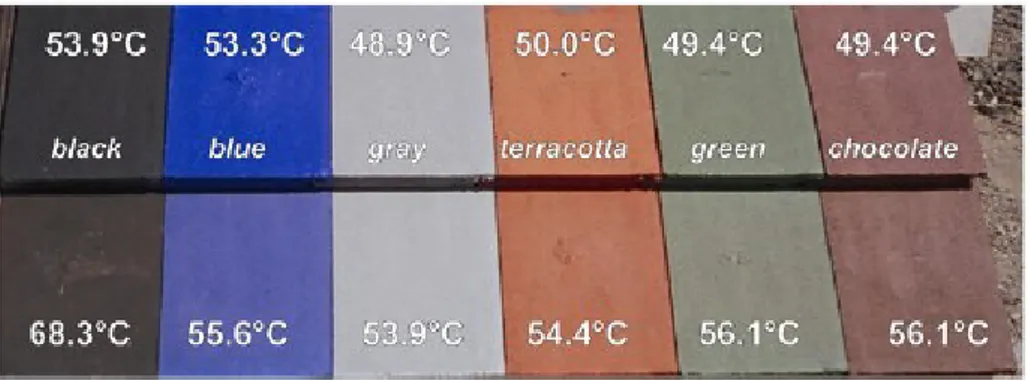
FIGURE 3.7: Standard and cool coatings for pavement tiles tested at the University of Athens [17] FIGURE 3.8: Test setup for the assessment of long-term solar reflectance used in Turkey [19] FIGURE 3.9: Test setup for the assessment of long-term solar reflectance used in Milan [20]
FIGURE 3.10: Solar reflectance variation (aged less initial) of different roofing membranes as a function of exposure time and for two different sites [20]
FIGURE 3.11: Visible and infrared pictures of the roof depicting the different surface temperatures achieved by the aged, the cleaned (first row) and new (second row) cool roofs [21]
FIGURE 3.12: The house investigated for the Iraklion case study [24] FIGURE 3.13: Roof surface temperatures before and after cool coating [24 FIGURE 3.14: The school building in Athens [25]
FIGURE 3.15: Annual heating (red bars) and cooling (blue bars) loads of the school building in Athens [25] FIGURE 3.16: Cool roof application in a school building in Trapani [26]
FIGURE 3.17: Cumulative distribution of the operative temperature in different rooms of the school building in Trapani before and after the application of a cool coating [26]
FIGURE 3.18: Collective dwelling studied by Bozonnet et al. in Poitiers [27] FIGURE 3.19: External view of the case study building in London [28]
FIGURE 3.20: Measured daytime surface temperature differences (outer-inner roof surface temperatures) for the building in London [28]
FIGURE 3.21: Measured Cool Roof Rating Council label for test cool roof products [30]
Chapter 4
FIGURE 4.1: Prospective view of the reference office building model (base configuration) [Author]
FIGURE 4.2: Madrid psychometric chart and outdoor temperature, global horizontal radiation and wind speed annual frequency distributions
FIGURE 4.3: Rome psychometric chart and outdoor temperature, global horizontal radiation and wind speed annual frequency distributions
FIGURE 4.4: Lyon psychometric chart and outdoor temperature, global horizontal radiation and wind speed annual frequency distributions
FIGURE 4.6: Stuttgart psychometric chart and outdoor temperature, global horizontal radiation and wind speed annual frequency distributions
FIGURE 4.7: The six variables affecting thermal comfort under Fanger’s theory (left) and the energy balance on a human body (right) [Internet]
FIGURE 4.8: Definition of the Intensity of Thermal Discomfort (ITD) index [17] FIGURE 4.9: Adaptive comfort categories for the city of Lyon, August [17]
Chapter 5
FIGURE 5.1: Operative temperature distribution over the month of July for the best thermal models of Athens. Top: r = 0.8. Bottom: r = 0.3 [Author]
FIGURE 5.2: Operative temperature distribution over the month of July for the best thermal models of Madrid. Top: r = 0.8. Bottom: r = 0.3 [Author]
FIGURE 5.3: Operative temperature distribution over the month of July for the best thermal models of Rome. Top: r = 0.8. Bottom: r = 0.3 [Author]
FIGURE 5.4: Operative temperature distribution over the month of July for the best thermal models of Lyon. Top: r = 0.8. Bottom: r = 0.3 [Author]
FIGURE 5.5: Operative temperature distribution over the month of July for the best thermal models of London. Top: r = 0.8. Bottom: r = 0.3 [Author]
FIGURE 5.6: Operative temperature distribution over the month of July for the best thermal models of Stuttgart. Top: r = 0.8. Bottom: r = 0.3 [Author]
FIGURE 5.7: Percentage of discomfort hours in July for each city. Top: r = 0.8. Bottom: r = 0.3 [Author] FIGURE 5.8: ITD calculation for Athens [Author]
FIGURE 5.9: ITD calculation for Madrid [Author] FIGURE 5.10: ITD calculation for Rome [Author] FIGURE 5.11: ITD calculation for Lyon [Author] FIGURE 5.12: ITD calculation for London [Author] FIGURE 5.13: ITD calculation for Stuttgart [Author]
FIGURE 5.14: ITD calculation for best comfort models. Top: r = 0.8. Bottom: r = 0.3 [Author] FIGURE 5.15: PE needs for Athens [Author]
FIGURE 5.16: PE needs for Madrid [Author] FIGURE 5.17: PE needs for Rome [Author] FIGURE 5.18: PE needs for Lyon [Author] FIGURE 5.19: PE needs for London [Author]
Chapter 1
TABLE 1.1: Different retrofitting scenarios for open plan (Type A) and cellular (Type B) office buildings [13]
Chapter 2
TABLE 2.1: Albedo restoration of different roofs for various washing methods [6] TABLE 2.2: Comparison of heat flows between ventilated and typical roofs [22]
Chapter 3
TABLE 3.1: Typical solar reflectance and infrared emittance values for roof covering materials [8] TABLE 3.2: Summary of the optical properties for cool materials to be applied to the roofs [11] TABLE 3.3: Solar reflectance values of standard and cool paving materials [11]
TABLE 3.4: Solar reflectance rates for each spectral range of new and one year aged specimens [19] TABLE 3.5: Albedo measurements for the two case study buildings [21]
TABLE 3.6: Field measurements of roof albedo after several years of coating [22]
TABLE 3.7: Estimated annual energy savings and peak reduction in July for all the 16 California climate zones [23] TABLE 3.8: Summary of US policies prescribing or suggesting the use of cool roofs [29]
Chapter 4
TABLE 4.1: Share of floor area for climate zone, construction period and number of floors [1] TABLE 4.2: Amount of floor area built within each reference period [1-2]
TABLE 4.3: Construction types for vintage period [1]
TABLE 4.4: Thermophysical properties of opaque construction materials [Author] TABLE 4.5: U-values for construction types, vintage period and city [1]
TABLE 4.6: Common simulation assumptions for all of the models [1] TABLE 4.7: Building features used for the parametric analysis
TABLE 4.8: Cities representative of different mid-latitude climates with Köppen-Geiger style classifications TABLE 4.9: Climatic characteristics of different sites (summer and winter daily averages)
TABLE 4.10: Primary Energy Ratio (PER) for different plant solutions
TABLE 4.11: Mean performance coefficients for summer and winter air conditioning devices
Chapter 5
1. INTRODUCTION
The rapidly growing building energy use has raised concerns globally. The contribution from buildings towards total national energy consumption, both residential and commercial, has steadily increased and reached figures as high as 40% in developed countries, and has exceeded the other major sectors such as industrial and transportation [1]. With the growing population, day-by-day increasing demand for building services and comfort levels, along with the rise in time spent inside buildings, energy demand in buildings will surely stick to the upward trend in the future. For this reason, energy efficiency in buildings is one of the prime objectives in design and retrofit at regional, national, and international levels. Within this framework, the topic of Zero Energy Buildings (ZEB) has received increasing attention in recent years, until becoming part of the energy policy in several countries. However, while new buildings can be constructed with high performance levels, the older buildings represent the vast majority of the building stock and are predominantly of low energy performance and subsequently in need of renovation work. With their potential in terms of energy and CO2 savings as well
as many societal benefits, energy efficient buildings can have a pivotal role in a sustainable future. The present chapter starts with a brief discussion on ZEB definitions and issues, and then develops considerations on the existing EU building stock and on the potential for its energy retrofit, thus framing the research topic of this thesis.
1.1 Towards nearly (or Net) Zero Energy Buildings
The nearly Zero Energy Building (nZEB) concept is one of many low-energy building movements that respond to the issues of climate change and energy security. The nZEB concept strives to reduce demand for energy and then to offset any residual energy consumption with CO2 free technologies. The
(re-)design focus for nZEBs is to reduce primary energy consumption, so as to be equal to or less than any generated renewable energy. This is an important concept since approximately 40 percent of all energy and emissions worldwide are building-related. If all buildings were designed and operated to be nZE, the energy could be used by other sectors, with a potential increase in energy security.
In Europe, article 9 of the EPBD (2010/31/UE) Recast requires that [2]: (i) by 31 December 2020, all new buildings are nearly zero energy buildings;
(ii) after 31 December 2018, new buildings occupied and owned by public authorities are nearly zero energy buildings.
A few exemplary non-residential renovation projects have demonstrated that total primary energy consumption can be drastically reduced, together with improvements to indoor environment quality, by means of passive and active systems. Because most (property) owners are not even aware that such savings are possible, they tend to set less ambitious targets: buildings that are renovated to mediocre performance can be a lost opportunity for decades.
Nevertheless, a further step towards the so-called Net Zero Energy Building (NZEB) is the desire to design buildings in a sustainable way [3]. There is considerable debate on how to define this design approach, particularly on how to calculate the balance between energy use and energy generation. Indeed, in principle a NZEB could simply be a traditional building that has its energy supplied by a very large renewable energy generation systems: if these systems deliver an equal or greater amount of energy than the building consumes, then it is a NZEB.
Obviously, this would not imply a reduction of global energy demand, since it would be theoretically possible to deliver as much energy as needed by means of renewable sources, thus buildings must be low energy ones, and have enough onsite renewable energy generation.
A graph explaining the concept of NZEB is reported in Fig. 1.1; here it is shown how the reference building energy needs should be first decreased (moving towards left on the energy demand x-axis), then covered by renewable energy sources. This definition was universally agreed.
If the energy supply should overcome the annual energy balance of the building, we talk of Positive/Plus Energy Buildings.
FIGURE 1.1: Graph representing the NZEB balance concept [4]
energy in materials, …), as these aspects lead to different definitions and different results as a consequence.
For example, insulation levels, HVAC system performance, photovoltaic or cogeneration system sizing and so on are directly dependent on the NZEB balance.
The biggest dispute concerns if the zero should be measured on site or off site, and which of the four traditional energy related units or metrics have to be used (see Fig. 1.2 for a scheme depicting the energy boundaries for the calculation).
Torcellini et al. [5] undertook an in-depth analysis about these issues, identifying the following definitions:
(i) Net Zero Site Energy: a building that produces at least as much energy on-site as it uses in a year;
(ii) Net Zero Source (Primary) Energy: source energy refers to the primary energy used to generate and deliver the energy to the site. It requires the imported/exported energy to be multiplied by appropriate site-to-source conversion factors;
(iii) Net Zero Energy Costs: the amount of money the building tenant pays for the energy services should be equal to or less than the amount of money the utility pays for the building energy exports to the grid;
(iv) Net Zero Energy Emissions/Carbon: building emissions from emissions-producing energy sources should be less than the equivalent ones produced by renewable energy sources (that are emissions-free).
The importance of a well-developed NZEB definition is highlighted when considering buildings that are being refurbished: firstly, refurbishment projects are more difficult because the building geometry, size and layout are pre-determined and not necessarily optimized to save energy. Secondly, very often all renewable energy supplies must be situated on site, and there is a lack of space for allocating them.
Some examples of successful NZEB all over the world are given in [6] where 23 selected projects are discussed, ranging across different functional typologies and sizes to illustrate implementation at different scales and in different climates.
For what concerns the office buildings sector (on which this thesis is focused, as will be explained in the next paragraphs), it is worth mentioning the renovation project of the WWF headquarters in Zeist (Netherlands, see Fig. 1.3). This building is regarded as the first carbon-neutral administration building in the Netherlands.
It is efficiently conditioned by using exhaust heat, which is stored in the ground by means of geothermal probes, as well as by a passive cooling system. Solar collectors cover a part of the heat required for the provision of hot water, while the remaining hot water and heating demands are covered by heat pumps.
The façade is clad in glazed ceramic tile supported by a wooden frame and wood panel sheathings, which enclose a 24 cm deep air cavity and a 12 cm thick insulating layer of mineral wool. The inner face is comprised of a vapor barrier and a 5 cm thick adobe render layer.
FIGURE 1.3: WWF headquarters in Zeist [Internet]
Openable windows combined with ventilation flaps in the lightweight timber construction elements ensure natural ventilation throughout the year. The large areas available for thermal exchange allow homogeneous temperature shifts and help avoid sudden temperature changes. In addition, the adobe retains moisture and improves the indoor climate.
The calculated demand parameters are strongly reduced with respect to the starting point, being now the total primary energy demand equal to 247 kWh m-2y-1 and the total primary energy generated 326 kWh m-2y-1.
The Pixel Building in Melbourne (Australia, Fig. 1.4) gives another example of the feasibility of NZEB projects, in a different climate. Here, passive strategies such as sunshade and daylight optimization reduce the need for cooling and heating, while recyclable materials minimize the amount of CO2
produced during the building construction. The photovoltaic arrays and the micro wind turbine power generators on the roof are sized to offset all climate gas emissions from the gas absorption heat pump and the other building service plants.
FIGURE 1.4: Pixel building in Melbourne [Internet]
The reinforced concrete floor slabs rest on the walls of the solid staircase core and on three precast concrete piers outside the insulated building envelope of the western façade. The windows recede by about a meter to provide architectural sunshade for the façade that receives a lot of sun during working hours.
Sufficient daylight can enter through the full-height windows while preventing direct solar radiation from heating up the rooms excessively. In addition to the intelligent exploitation of daylight, an energy-efficient lighting system (fluorescent tubes) in the office ensures low heat loads: they are
dimmed in accordance with the amount of daylight and connected to presence sensors. In all other rooms apart from the offices LED lighting is used.
To passively cooling the building during the night, the windows of the upper floors open automatically on cool nights, allowing cold air to flow across the solid ceiling slabs and withdraw the heat stored during the day.
The vertical axis wind turbines on the roof are also a unique feature that makes the theme of renewable energy clearly visible; they are not affected by the frequent change in wind direction and allow an even generation of 1.7 kW of electricity at a wind speed of 8 m/s. The renewable energy system is completed by a photovoltaic array measuring 38 m2, mounted on three solar trackers (dual axis system that follows the sun).
The resulting primary energy demand amounts to 123 kWh m-2y-1, while the primary energy generation is equal to 84 kWh m-2y-1.
1.2 EU buildings stock
Amongst the current political discussions at EU level, Buildings Performance Institute Europe (BPIE) has undertaken an extensive survey across all EU Member States, Switzerland and Norway reviewing the situation in terms of the building stock characteristics and policies in place. This survey provides an EU-wide picture of the energy performance of the building stock, and is hereafter called as a basis for determining existing buildings features [7].
European countries have been divided up into three regions, according to climatic, building typology and market similarities:
(i) North & West; (ii) South;
(iii) Central & East.
FIGURE 1.5: EU Countries considered within BPIE survey together with population and floor distribution breakdown [7]
The five most populated countries (France, Germany, Italy, Spain and the UK) account for approximately 65% of the total floor space, thus there is no surprise in finding out that the corresponding share of population in these countries is equal to 61% of the total.
The residential stock is the biggest segment, accounting for 75% of the building stock (see Fig. 1.6); an analysis of this sector indicates that 64% of the residential floor area pertains to single-family houses, whereas the remaining 36% to apartment blocks.
The split between the two main types of residential buildings vary significantly amongst the countries, but share the same little rate of annual new buildings, which approaches 1% over the period 2005-2010.
It is important to know how a great share of the stock in Europe is older than 50 years, and many buildings still operating nowadays are hundreds of years old, being constructed when energy building regulations where very limited or absent.
The BPIE report also focuses on the final energy use in the residential sector within the period 1990-2010, rebating that European households are responsible for the 68% of the total final energy use in buildings, being space-heating the dominant energy end-use.
The final energy use in the residential sector in Mtoe (Million tons of oil equivalent), split into fuels and electricity needs, is shown in Fig. 1.7 together with heating degree days (nominal and actual). By analyzing this picture, it is possible to notice a decrease in the fuels needs (mainly for space heating, which represents about 70% of total final energy use) and a parallel increase in the electricity needs (mainly for space cooling). A likely explanation for these trends could be found in both the increased insulation levels of the building envelopes and the augmented outdoor air temperatures found within the cities (a phenomenon known as Urban Heat Island effect).
FIGURE 1.7: Final energy use in the residential sector [7]
For what concerns the non-residential sector, understanding its energy use is complex because end-uses such as lighting, ventilation, heating, cooling, refrigeration and appliances vary greatly from sector to sector (sport facilities, wholesale and retail, hotel & restaurants, hospitals, educational buildings and offices).
Moreover, the electricity demand within this sector has increased tremendously in the last 20 years, by 74% as shown in Fig. 1.8, probably due to an increasing penetration of IT equipment and air conditioning systems.
FIGURE 1.8: Final energy use in the non-residential sector [7]
If looking at the share of total energy use per building type (Fig. 1.9), it appears how the office and commercial buildings sectors account for more than 50% of energy needs, thus highlighting a big opportunity for implementing energy saving measures in this kind of buildings, especially for lowering the electricity needs.
1.3 Characteristics of the Office Buildings sector in EU-27 countries
The increasing interest in the office buildings sector is underlined by a recent IEA task (Task 47: Renovation of Non-Residential Buildings towards Sustainable Standards, [8]), aimed at showing how total primary energy consumption can be reduced by means of building’s passive and active systems.
The objectives of this task are “to develop a solid knowledge-base including: how to renovate non-residential buildings towards the Net Zero Energy Building standards in a sustainable and cost efficient way; ways to identify important market and policy issues; and effective marketing strategies for such renovations”.
In a European-based perspective, a very comprehensive and up-to-date study about the EU building stock, with a focus on office buildings, is reported in [9].
Firstly, a recognition of the size, age, type of tenure of the building stock is given, based on previous EU reports such as TABULA, ENTRANZE, BPIE and Odyssee, and on semi-structured interviews with research institutions.
Secondly, a detailed analysis of building types and constructions, as well as their thermal performance and energy consumption, is provided by splitting the stock analyzed into seven different climate zones.
Finally, building energy models representative of different vintage periods are developed as base cases for studying energy efficiency measures.
The information collected during the literature review has been presented in a database specifically created for the Inspire project in Microsoft Excel format, and is attached in Appendix I. Here the main findings are summarized, and most of them are used for creating the base models for the energy assessment carried out in Chapter 4 by means of dynamic thermal simulations.
For what concerns the total floor area, in the EU-27 is approximately 1.25 billion m2, of which 0.98 billions m2 are heated; the majority of it (about 70%) lies in the six biggest countries (Spain, Italy, France, Germany, UK and Poland), and this reflects the size of the population in these countries.
Very little is known about the age of the current office stock, and in particular for those buildings constructed pre-1980. However, what is clear from this survey is that although a large proportion of the office stock dates before 1980, the office stock is generally younger than the residential stock (see Fig. 1.10 for the age breakdown).
FIGURE 1.10: Age construction breakdown for EU-27 countries [9]
Most of the office stock in EU-27 is privately owned, and this varies across all of the countries from 30% to 84%; the remaining part is publically owned. The type of tenure represents an important aspect for refurbishing programs intended to reduce energy bills, as the costs of installing retrofit measures and the consequent benefits apply to the same individuals.
Construction types are found to be pretty much the same in most countries – concrete structural frame with curtain walls is the most widespread – despite they can show different numbers of floors, different shapes or type of offices. This last aspect makes the office stock very hard to categorize; nevertheless, the iNSPiRe survey found three main construction typologies based on the fact that facades are the components mostly affecting the building thermal behavior.
These typologies are:
(i) Brick structural walls: typically built before 1945 (end of World War II), they are often low-rise blocks;
(ii) Concrete structures: bricks or concrete panels are mainly used within the period 1945-1964, while curtain walls spread during the 1970s and 1980s;
(iii) Concrete structures with reinforced cement: statistics show how these structures dominate the stock and curtain walling is the most common type of façade. The majority of them incorporate glazing.
The three categories represent the base for developing thermal models aimed at giving a broad view of the energy needs for air conditioning (cooling + heating), artificial lighting and ventilating, and thus implementing measures for their effective refurbishment. The models are shown in the following data sheets and will be further discussed in Chapter 4, where the methodology for characterizing the “typical” model used for simulation purposes is detailed.
FIGURE 1.11: Office building 1 [9]
Reference Office 1 represents a category of buildings built in pre 1970s and most typically during the 1950s and 1960s, however small office buildings continued to be built from masonry. The main construction consists of walls and floor slabs made in situ. The structure consists of brick walls. Most buildings are constituted of usually 2 floors for an average total office of between 1800 and 3000 m2.
When these buildings were built, no legal energy requirement existed yet as regulations only really started to come into effect during the 1970s. The lack of insulation in the facades and roofs contributes to a high heating demand. The heating generation is accomplished by fuel oil or gas boiler and distributed by radiators. The cooling demand depends on the location, so it is very variable.
The windows are double glazed and have internal shading, while the roof consists of a flat concrete slab on wooden beams, with a bitumised surface.
FIGURE 1.12: Office building 2 [9]
The buildings represented by the Reference Office 2 were mainly built between 1945 and 1970, although they became most typical during the 1960s. There is little or no insulation in the buildings in this category, and the number of floors is between two and seven, with an average total floor area of approximately 4000 m2.
A basement with limited parking, building services, and storage space is also present. Precast concrete cladding panels on a concrete frame form the outer envelope of the building, while the windows are double glazed and have internal shading.
FIGURE 1.13: Office building 3 [9]
The statistics showed that concrete structures dominate the stock and curtain walling is the most common type of façade. The majority of curtain walls incorporate glazing. This category is the most recent, with buildings built between 1960 and 1980, and covers buildings with a concrete structure of reinforced cement (Reference Office 3).
Window frames with aluminum panels form the outer envelope of the building, fitted between the concrete pillars and beams. Effectively each façade has three elements to the thermal envelope: concrete, aluminum, and glass. The windows are double glazed and have internal shading.
As far as energy needs are concerned, specific space heating consumption is highest in the Northern Continental region (at 238 kWh m-2 year-1) and lowest in Southern Dry at 54 kWh m-2 year-1. The EU-27 weighted average for space heating consumption is 161 kWh m-2 year-1 and 10 kWh m-2 year
-1
for domestic hot water.
Lighting energy consumption ranges between 25-71 kWh m-2 year-1, being the EU-27 weighted average approximately 39 kWh m-2 year-1.
Detailed information about the fuel use in office buildings is limited, showing a high degree of variation in the primary and secondary fuels used. However, some fuels are strongly preferred in certain countries, due to availability and geopolitical reasons:
Coal: Slovakia, Poland and Lithuania;
Electricity: all countries, but particularly in Cyprus, Greece, Malta and Spain; Wood: Bulgaria, Latvia and Portugal;
Gas: UK, Slovakia, Netherlands, Luxembourg, Germany, Hungary and Czech Republic; Oil: Belgium, Cyprus, Ireland, Spain and Slovenia.
1.4 Typical refurbishing actions for office buildings
Several studies have focused generally on the issue of refurbishing existing office buildings. In general, they are based on the concept that the use of an energy-efficient façade is indispensable for reducing the energy demand for air conditioning [10-11].
FIGURE 1.14: Relationship between refurbishment scope and ability to influence carbon emissions [10]
In fact, since facades act as a physical barrier between the indoor and outdoor environments, interventions aimed at improving its performance are considered as one of the most effective ways to both reduce energy consumption in buildings and improve their indoor environmental quality.
Additional thermal insulation, installation of high-performance glazing systems, and passive measures such as natural ventilation, shading systems, and the use of daylighting are all beneficial
interventions in that respect. Some authors suggest that an improved insulation is more important than an insulated solar control in existing, poorly insulated office building [12].
There are, however, counter-arguments which suggest that traditional means of improving façade thermal performance are likely to increase cooling loads during warm/hot seasons [13].
The upgrade from standard single or double-glazing to high efficiency double glazing to reduce heating loads has been considered as the most effective way to reduce the negative environmental impacts as a result of poor performance of old façade components, as reduction in space heating in some cases has been recorded to be around 35% [14].
FIGURE 1.15: Example of double skin glass façade (a,c) and green façade (b) [15]
Different retrofitting strategies have also been investigated for different types of office buildings in different climatic conditions. Among these strategies, many relate to elements of the building façade such as the improvement of wall insulation, the replacement of windows and window frames, the use of shading devices and the maximum deployment of natural ventilation.
Such interventions resulted in significant energy reductions for all the office types in all the climatic regions, with values ranging from 20% up to 50% [13, 16].
TABLE 1.1: Different retrofitting scenarios for open plan (Type A) and cellular (Type B) office buildings [13]
Beneficial effects due to façade improvements, related to heating/cooling loads reduction, natural ventilation and appropriate shading are echoed also by Wong et al. [17] and Jin and Overend [18].
To summarize, three main conclusions related to office buildings refurbishment can be drawn from this brief literature review:
Notable energy reduction is achievable; Significant carbon emissions can be saved;
1.5 Research topic and significance of the study
Within this context, the present research aims at exploring the benefits stemming from the application of a passive cooling technology, namely the application of cool materials to existing office buildings roofs, in terms of improvement of thermal comfort conditions and reduction in the energy needs.
Despite the concept of cool roofs is well known in US since 1990s, many studies focused on their performance in the residential/commercial sectors under various climatic conditions (see Chapter 3) for US countries, while only a few exemplary case studies are analyzed in EU countries.
Given this, after the characterization of the existing buildings stock in the EU (Chapter 1) – with a particular focus on office buildings - the thesis work gives an insight into roof energy balances due to different technological solutions (Chapter 2). Chapter 3 describes in detail the physical properties of cool materials and their availability on the market, thus providing a solid background for the parametric analysis developed in Chapter 4 aimed at evaluating cool roofs performance for various climates and office buildings configurations.
By using detailed numerical models, the thermal behavior of representative office buildings of the existing EU buildings stock is deeply assessed in terms of thermal comfort and energy needs for air conditioning (Chapter 5). Finally, an economic analysis carried out in terms of payback time will discuss the convenience of this solution for passive cooling purposes.
1.6 References of the chapter
[1] International Energy Agency, 2014. Link: www.iea.org/aboutus/faqs/energyefficiency/
[2] Directive 2010/31/EU of the European Parliament and of the Council of 19 May 2010. Link:
http://eur-lex.europa.eu/LexUriServ/LexUriServ.do?uri=OJ:L:2010:153:0013:0035:EN:PDF
[3] N. Rajkovich, R. Diamond, B. Burke, Zero net energy myths and modes of thought, Proceedings of ACEE Summer Study on Energy Efficiency in Buildings, Pacific Grove, California, 2010. Link:
http://aceee.org/files/proceedings/2010/data/papers/2125.pdf
[4] I. Sartori, A. Napolitano, K. Voss, Net zero energy buildings: A consistent definition framework, Energy and Buildings 48 (2012) 220-232
[5] P. Torcellini, S. Pless, M. Deru, D. Crawley, Zero Energy Buildings: A critical Look at the Definition, Proceedings of ACEE Summer Study, Pacific Grove, California, 2006. Link:
http://www.nrel.gov/docs/fy06osti/39833.pdf
[6] K. Voss, E. Musall, Net Zero Energy Buildings, International projects of carbon neutrality in buildings, Detail Green Books, Varennes (Canada), 2011
[7] BPIE, Europe’s Building Under the Microscope. A country-by-country review of the energy
performance of buildings, 2011. Link:
http://www.europeanclimate.org/documents/LR_%20CbC_study.pdf
[8] International Energy Agency Solar Heating and Cooling Task 47, 2014. Renovation of Non-Residential Buildings towards Sustainable Standards. Link: http://task47.iea-shc.org/publications
[9] iNSPiRe Project, Survey on the energy needs and architectural features of the EU buildings stock, 2014.
Link: http://www.inspirefp7.eu/about-inspire/downloadable-reports/
[10] Carbon-Trust, Low Carbon Refurbishment of Buildings, A guide to achieving carbon savings from refurbishment of non-domestic buildings, 2008
[11] CIBSE, CIBSE TM 53: 2013-Refurbishment of non-domestic buildings in Great Britain, 2013 [12] L. Thomas, Evaluating design strategies, performance and occupant satisfaction: a low carbon office refurbishment, Building Research Information 38:6 (2010) 610-624
[13] E. Dascalaki, M. Santamouris, On the potential of retrofitting scenarios for offices, Building and Environment 37:6 (2002) 557-567
[14] I. Blom, L. Itard, A. Meijer, Environmental impact of dwellings in use maintenance of façade components, Building and Environment 45:11 (2010)
[15] S. F. Larsen, L. Rengifo, C. Filippin, Double skin glazed facades in sunny Mediterranean climates, Energy and Buildings 102 (2015) 18-31
[16] M. Santamouris, E. Dascalaki, Passive retrofitting of office buildings to improve their energy performance and indoor environment: the OFFICE Project, Building and Environment 37 (6) (2002) 575-578
[17] I.L. Wong, P.C. Eames, S. Perera, Energy simulations of a transparent-insulated office façade retrofit in London, UK, Smart Sustainable Built Environment 1 (3) (2012) 253-276
[18] Q. Jin, M. Overend, Façade renovation for a public building based on a whole-life value approach, in: Proceedings of Building Simulation and Optimisation Conference 2012, Loughborough, 2012, 378-385
2. ROOF TECHNOLOGIES AND THEIR ENERGY BEHAVIOR
The building’s energy demand is closely connected to the efficiency of its envelope; in fact, if the building envelope is not correctly designed, the heat fluxes through the structures (vertical, horizontal, transparent and opaque) are the cause of a large increase in energy consumption. Therefore it is very important to develop alternative construction techniques that guarantee both thermal comfort and low energy use. Generally, thermal building regulations have the aim to reduce the energy needs for air conditioning, but usually the proposed solution is the overinsulation of buildings that could reduce the effectiveness of traditional passive strategies (thermal mass, ventilation) and create adverse effects on indoor thermal comfort. In regions with hot climates, such as Mediterranean countries, the roofs during the summer receive large amounts of solar radiation and their superficial temperatures can reach values up to 75°C [1]. Obviously, this causes a significant risk of overheating, making consequently the cooling of the building very expensive [2].
A possible way to cope with this problem is the reduction of heat fluxes through the building envelope by using technologies such as cool roofs, green roofs and ventilated roofs. In the following, an overview of these solutions will be given, together with the energy balance equations that govern the physical problem.
2.1 General overview of Cool Roofs (CR)
“A roof with high solar reflectance (ability to reflect sunlight) and high thermal emissivity (ability to radiate heat) stays cool in the sun, reducing demand for cooling power in conditioned buildings and increasing occupant comfort in unconditioned buildings” [3].
Levinson defines Cool Roofs in this way: they are particular materials having a high solar reflectance r - thus reducing heat gains during daytime - and a high thermal emissivity ε that enables them to dissipate the heat absorbed during night. However, while these are key features, other parameters are of main interest for the energy balance of a roof, such as its extension compared to the opaque envelope (known as roof-to-wall ratio) and the thermal resistance R of the whole roof components.
As stated in the introduction, traditionally building codes have focused on more roof insulation, i.e. high R-values, but more recently the extent of energy savings and comfort benefits of roofs with a
In fact, the raise of roof R-values - and consequently of insulation costs – reduces daytime heat gains but at the expense of nighttime heat losses, and this is inferable from the energy balance reported in Eq. (2.1) for steady-state conditions, that is to say without considering the heat capacitance of the roof:
Eq. (2.1) states that the solar radiation absorbed by the roof surface qabsorbed is partially released to
the outdoor environment, both by infrared radiation (qradiant) and by convection (qconvective). The
contribution of these terms is strongly affected by the roof surface temperature Tso. Moreover, heat
transfer occurs through the roof by conduction (qtransferred): this contribution is proportional to the
difference between the outdoor air temperature To and the indoor temperature Ti, while depending on
the thermal resistance Rassociated to the roof layers and to the heat transfer on the inner surface of the roof.
FIGURE 2.1: View of cool roofs in Honolulu, Hawaii [Internet]
It is clear from the previous equation how the main parameters determining the cool roof performance are the solar reflectance r, the thermal resistance Rand thermal emissivity ε, although a significant contribution to the heat balance is provided also by the convective coefficient hc.
A very interesting study on the influence of the three parameters (r, R, ε) on the peak heat gains and daily average cooling loads (over six summer months), per 100 m2 of a flat roof located in Sydney, is carried out by Gentle et al. [4] by means of dynamic simulations.
The main results are reported in Figs. 2.2-2.3, which show the peak cooling load in January (southern hemisphere) and the average cooling load per day over the cooling season, respectively. Eighteen different combinations of the three parameters are taken into account, with the aim of considering reasonable values for all of them. The cooling set point is 25°C, and the figures refer to different combinations of solar absorptance (Asol = 1-r), thermal emissivity (E= ε) and thermal resistance
(R).
More in detail, Fig. 2.2 reveals how cooling loads rapidly rise as R decreases at low r, in contrast with the small rise with 1/R that occurs at high r. It is also important to notice how the peak load is smaller at Asol = 0.2 and R = 1.63 compared to all cases with Asol > 0.6 when R = 3.06, thus demonstrating
how a low solar absorptance should be the dominant concern. Moreover, these peak loads can be reduced in magnitude by factors of 2.5-3.5 by lowering Asol (i.e. by increasing r), whatever R is
considered.
FIGURE 2.2: Peak heat gains (kW) per 100 m2 of a flat roof as a function of different combinations of Asol, E and R values [4]
For the same parameter set, Fig. 2.3 shows the average cooling load per day over the six months cooling season. It is important to pinpoint that the sensitivity to lowering of the E value from 0.9 to 0.6 increases as both more solar energy is absorbed by the roof and more is transmitted inwards.
Although high E appears less important if Asol is small at all R, the thermal resistance should not get
Moreover, if comparing Figs. 2.2-2.3 it is possible to observe how they are qualitatively similar in shape, but for each change in thermal resistance Asol have a bigger impact on average daily load than on
peak load.
FIGURE 2.3: Daily average cooling loads per 100 m2 of a flat roof as a function of different combinations of Asol, E and R values [4]
In order to fully appreciate how much cool roofs can help improve building thermal performance, it is important to focus on the values currently achievable by solar reflectance r; these values obviously depend on the chemical agents used to produce a cool paint, and can achieve values higher than 0.8. However, it is well known that cool paints usually undergo soiling and weathering in the first months after installation, which significantly reduce their solar reflectance. As an example, Akbari [5] reported on a reduction of about 10% in only two months in the solar reflectance of a white coating having an initial r = 0.8; another field study measuring the effects of aging and weathering on ten roofs in California found that the reflectance of cool materials can decrease by as much as 0.15, due to the deposition of soot and dust, mostly within the first year of service [6].
This aging process is shown in Fig. 2.4, where the effects of two months to six years of accumulation of environmental pollutants on the albedo of different roofs is measured. The data indicate that most of the decrease in albedo occurs in the first year, possibly in the first few months, being the cementitious coating on gravel substrate the technical solution ensuring the smallest and most gradual decrease in albedo.
In order to assess the effects of the cool materials aging process on cooling energy savings, the same authors assume a linear approximation for the relationship between albedo and surface
temperature as an indicator of the magnitude of the heat transfer through the roof. In this way, energy savings are proportional to the reduction in the heat fluxes incoming through the roof.
For testing this hypothesis, the cooling needs of real buildings were monitored over the summer period, at the beginning of which the albedo of the roof was measured at 0.73, and the original value (before the coating) was 0.18. The estimated energy savings reported are about 80% (270 kWh/year).
After one year of exposure, roof albedo had dropped to 0.61, thus they estimate long-term cooling energy savings to be 20% lower than first year savings.
FIGURE 2.4: Variations in albedo for different exposure time for various flat roofs in California [6]
A slightly different message is conveyed by Bretz and Akbari [7], who demonstrated that washing the roof surface could almost restore the original solar reflectance.
In the framework of an experimental campaign, most roofs were washed with soap and water, using a mop while other were washed differently, for the sake of comparison among the different methods.
The restoration in albedo (expressed as a percentage of recovery with respect to the original value) resulting from the washing process was found to be generally significant. When surfaces were rubbed with soap, the albedo was restored to within 90% of the original value, indicating that the loss of albedo is not permanent, and it is caused by dirt accumulation rather than by UV or hydrolytic degradation (see Table 2.1 for details).
For further details on this phenomenon, the reader can refer to Section 3.3 where several long-term albedo assessments are described for different cool materials.
As for the values assumed by thermal emissivity ε, it can be assumed almost constant for a great variety of roofing materials and very close in value to that of a grey body (usually ε = 0.9 can be assumed for non-metallic materials).
Finally, Eq. (2.1) states that it is also important to make an appropriate choice for the convective coefficient hc, as remarked in [8]. Indeed, under typical summer conditions occurring in a hot-humid
climate such that of Southern Italy (I = 800 W m−2, ϕ = 60%, 25 ≤ To ≤ 35 °C) - and for a fixed value of the
thermal resistance of the roof (R = 1.40 m-2 K W-1) - it is easy to notice that the choice of hc has a strong
influence on the temperature difference ∆T between the roof surface temperature Tso and the outdoor
temperature To (Fig. 2.5).
This is true for a low reflective coating (r = 0.25), for which ∆T differences up to 5°C should be expected when increasing hc by 5 units step (W m-2 K-1), while if looking at the high reflective coating (r =
0.85) this temperature difference is extremely less sensitive to hc. In this case, the roof temperatures are
expected to be only few degrees above the outdoor air temperature.
FIGURE 2.5: Difference between roof outer surface temperature and outdoor temperature as a function of hc [8]
Moreover, the increase in hc also affects the heat flux q incoming through the roof, as shown in
Fig. 2.6 for the same r values seen in the previous graph. Here both the low and high reflective finishing layers of the roof follow a trend very close to that shown in Fig. 2.5. This rebates how important is a correct evaluation of the convective heat transfer coefficient, especially for low to moderate reflective
roofs, for making reliable predictions on the potentiality of cool roofs as a strategy to improve thermal performance of existing buildings.
FIGURE 2.6: Heat flux incoming through the roof as a function of hc [8]
2.2 General overview of Green Roofs (GR)
Green roofs represent a promising adaptation strategy for facing climate changes, and the number of green roof studies has consequently increased in recent years. The thermal effects of a green roof mainly result from the shading, insulation, evapotranspiration and thermal mass of the plants and their substrate, with the additional contribution of the high specific heat of the water contained in the substrate to the thermal inertia of the whole “green” package.
In addition, evapotranspiration from a green roof brings a cooling effect, since experiments demonstrate that latent heat can override sensible heat on a green surface, and leaf transpiration accounts for almost 30% of rooftop cooling.
Moreover, the insulation role of green roofs can mitigate indoor peak temperatures, saving both cooling and heating loads, and decreases the heat flux entering the roof by 60% according to the roof design.
FIGURE 2.7: View of green roofs in Stuttgart, Germany [Internet]
Parizotto and Lamberts [9] investigated the thermal performance of a green roof in Florianopolis (Brazil) for both warm and cold periods by means of field measurements. Heat fluxes, green roof’s temperature profile and water volumetric content in substrate layer were monitored, together with internal air temperature of rooms.
They found out that during the warm period (1-7 March 2008), the green roof reduced heat gain by 92%-97% in comparison to ceramic and metallic roofs respectively, and enhanced the heat loss to 49% and 20%. During the cold period (25-31 May 2008), the green roof reduced heat gain by 70% and 84%, and reduced the heat loss by 44% and 52% in comparison to ceramic and metallic roofs, respectively. From the derived data, it has been confirmed that green roof contributes to the thermal benefits and energy efficiency of the building in temperate climate conditions.
A comparison among different passive cooling technologies under hot-humid climatic conditions and for highly-insulated slabs has been carried out by D’Orazio et al. [10], who performed an experimental assessment of the yearly performance of all of the different technologies. The goal was to understand whether in summer the passive cooling effects are inhibited by the low thermal transmittance recently introduced in many southern Europe countries to meet the demands of the energy savings regulations for the winter heating season.
The results of this field study show that, despite thermal fluxes do not turn out to be very different from those of other roof solutions - because of low transmittance of the systems - passive cooling effects are not negligible. This is due to the presence of fluxes going out of the slab 40% of the time during the summer season considered, and by significant delay of incoming heat fluxes waves.
During winter, the green roof produces a further insulating effect in the covering that contributes to reducing thermal dispersion also in wet or saturated conditions.
Similar results are obtained by Lazzarin et al. [11], who performed a series of measurement sessions on a green roof installed on the Vicenza Hospital roof (northern Italy), finding how relevant is the role played by the latent flux of the evapotranspiration process. In fact, during summer – with the soil in almost dry conditions – the green roof allows an attenuation of the thermal gain entering the underneath room of about 60% with respect to a traditional roofing with an insulating layer.
That is due to the higher solar reflection of the greenery, while the evapotranspiration contribution is quite limited. When the soil is in a wet condition, not only the entering flux is cancelled, but also a slight outgoing flux is produced so that the green roof works as a passive cooler, thanks to the cooling effect of evapotranspiration. During winter, the evapotranspiration process is driven above all by the air vapor pressure deficit, able to produce an outgoing thermal flux from the roof that is 40% higher than the corresponding one of a high solar absorbing and insulated roof.
As briefly described above, green roofs can achieve the expected goals if properly designed, but it is necessary to simulate their effectiveness in relation to local conditions before construction.
Modeling green roofs involves the study of mass and heat transfer through the different layers, as well as plant physiology. Several models are available in the literature: the simplest models only consider the reduction of roof thermal transmittance based on in-situ measurements (Fig. 2.8, [10]), while other studies analyze more in detail the complex phenomena due to foliage shading and evapotranspiration [9].
Among all of the models proposed in the literature, the mono-dimensional one developed by Del Barrio [12] divides a green roof in three different layers: the canopy, the soil and the support. By imposing the horizontal homogeneity of the roof slab, heat and mass fluxes are assumed to be mainly vertical, so one-dimensional equations can be adopted to describe the thermal behavior of each layer. This model has been validated through a sensitivity analysis using Athens meteorological data and a concrete roof slab of 10 cm. Its approach represents the main reference for other one-dimensional models, such as those developed by Kumar and Kaushik [13] or by Lazzarin et al [11].
On the other hand, two-dimensional models are much less common: an example in the literature is given by Alexandri and Jones [14], aimed to evaluate the thermal effect of green roofs and green walls. Anyway, nowadays the one-dimensional EcoRoof model developed by Sailor [15] is maybe the most used one, and thanks to its high reliability it has been implemented in the software tool EnergyPlus (Fig. 2.9 gives a representation of the heat fluxes occurring at different layers).
FIGURE 2.9: Energy balance for a green roof, including latent heat flux (L), sensible heat flux G, shortwave (I) and longwave radiation (LW) [15]
Based on the previous work of Frankenstein and Koenig [16], who developed the FASST (Fast All-Season Soil Strength) model, Sailor considers two heat fluxes for the green roof, respectively at the foliage surface Ff (see Eq. 1) and at the ground surface Fg (see Eq. 2.2):
As it is possible to observe from Eq. (2.2) and Eq. (2.3), in both cases the energy balance is split into a radiant term, a sensible and latent heat exchange and a conductive heat flux for the soil. The radiant term considers the heat exchange with the sky (at short and long wavelengths) and the mutual heat transfer between foliage and ground layers. Actually, this model does not allow the soil thermal properties (specifically solar reflectance, thermal conductivity, specific heat capacity and density for dry soil) to vary according to the moisture content of the soil media, because of stability issues during the calculation [17]. However, a simplified moisture balance that allows to consider precipitation, irrigation and moisture transport between two soil layers (top and root zones) is already implemented; future improvements in this direction are in any case necessary, as highlighted in [18]. In fact, moisture can leave the soil by means of evaporation, and the vegetation by evapotranspiration: these phenomena are influenced by water runoff in the soil layer due to saturation-excess and infiltration-excess [19]. Given this, EnergyPlus allows the user to define a series of parameters, for both the soil layer and the foliage, to fully characterize the green roof.
Olivieri et al. [20] have carried out a sensitivity analysis by varying all the parameters that define the EcoRoof routine in the range allowed by the software, and have found that, for an extensive green roof in the Mediterranean coastal climate, only four parameters have a strong influence on the roof performance and must be carefully considered.
compared with the value obtained using all default variables; a variation of less than 10% compared with the default value was considered not significant.
The most important parameters are found to be: the height of plants (hp);
the Leaf Area Index (LAI), defined as the ratio of the projected leaf area to the overall ground area;
the minimum stomatal resistance (msr), which represents the resistance of the plants to
moisture transport;
the dry soil conductivity (K).
2.3 General overview of Ventilated Roofs (VR)
Natural ventilation of a roof cavity seems to be an attractive measure to dissipate solar radiation outdoors before excessive heat is transferred into the occupied space indoors.
The ventilation of a roof or an attic has become one of the greatest interests for building researchers in the last several decades as a measure to decrease attic temperatures and cooling load in an occupied space.
When naturally ventilating a roof, induced air movement by solar irradiation must be pursued in depth, considering the buoyancy of hot air as a self-induction force acting favorably even when wind force is not available [21].
Ventilated roofs may adapt to the geometry configuration of existing flat or tilted roofs (see Figure 2.11); however, in order to evacuate accumulated hot air from an attic, several studies indicates that the most effective form of ventilation is given by a combination of ridge and soffit vents [22].
FIGURE 2.11: Schematic representation of flat (top, [21]) and pitched (bottom, [22]) ventilated roofs
The ventilation of the roof may be created by natural or forced convection: natural convection (buoyancy effect) is generated by difference of temperatures; mechanical apparatus (i.e. fans) generates forced convection.
Solar radiation heats the outdoor air within the air gap; the warm air becomes lighter and creates an upward flow. This airflow produces advantageous effects because it reduces the heat storage in the structure while reducing the heat flux through the roof. This is shown in Fig. 2.12, where the upper and lower surface temperatures of a metallic cavity roof and of a single roof are compared for the Japanese city of Toyohashi City [21].
In daytime, the upper surface temperatures of the cavity are significantly lower than those of the single roof: the highest temperature difference is registered at noon, and amounts to about 20°C. During the night, the upper surface temperatures of both roofs fell slightly below the outdoor air temperature.
Moreover, the lower surface temperature of the cavity roof was much lower than that of the single roof in the daytime, being approximately the same during night.
FIGURE 2.12: Comparison of upper and lower roof surface temperatures [21]
If looking at the corresponding hourly cooling load (Fig. 2.13), it can be observed how they became negative at night for the ventilated roof, thus theoretically requesting some heating, while peak values are almost split in half.
FIGURE 2.13: Comparison of cooling loads [21]
During the winter season, the air temperature within the ventilated roof is approximately the same as of the outdoor environment, because the solar radiation has low intensity resulting with much reduced stack effect.
A study aimed at comparing the thermal performance of ventilated and traditional flat roofs for the hot-arid climate of Athens (Greece), with the help of well-insulated test cells, was undertaken by Dimoudi et al. [23].
The ventilated roof component consisted of a 12 cm reinforced concrete slab in direct contact with the underneath room, 5 cm thick layer of extruded polystyrene placed on top of the concrete slab, the ventilation air gap (6 cm and 8 cm gap heights are tested) and 2.5 cm reinforced concrete slab facing outdoor.
In the center of the ventilated roof, a circular chimney of 35 cm height and 5 cm diameter made of metal sheet and painted black externally, was used for improving the extraction of hot air from the gap.
A constant room temperature of 27°C was applied in the interior of the test cell during the whole testing period.
The relative difference of the heat flow for different layout configurations (Phases 2-3 refer to an air gap height of 8 cm, while Phases 4-5 to an air gap height of 6 cm) - considering also the presence of a radiant barrier (Phases 3 and 4) - is shown in Table 2.2.
Here, the percentage difference of the ventilated roofs heat fluxes with respect to the traditional roof ones (performance indicator A) is reported for daytime, nighttime and for the whole 24 hours.
TABLE 2.2: Comparison of heat flows between ventilated and typical roofs [23]
It can be inferred that the ventilated roof performs better than the typical during summer daytime, while the opposite is true for summer nighttime; on a 24 h basis, the ventilated roof presents better thermal performance than the typical one.
The radiant barrier (Phases 3 and 4) enhances the performance of the ventilated roof during summer daytime by reducing thermal gains, while during nighttime it is unfavorable for the
![FIGURE 1.5: EU Countries considered within BPIE survey together with population and floor distribution breakdown [7]](https://thumb-eu.123doks.com/thumbv2/123dokorg/4478924.32265/19.892.285.694.105.458/figure-countries-considered-bpie-survey-population-distribution-breakdown.webp)
![FIGURE 2.3: Daily average cooling loads per 100 m 2 of a flat roof as a function of different combinations of A sol , E and R values [4]](https://thumb-eu.123doks.com/thumbv2/123dokorg/4478924.32265/37.892.271.707.211.503/figure-daily-average-cooling-function-different-combinations-values.webp)
![FIGURE 2.8: In situ thermal transmittance assessment for various green roof solutions [10]](https://thumb-eu.123doks.com/thumbv2/123dokorg/4478924.32265/42.892.270.717.729.1033/figure-situ-thermal-transmittance-assessment-various-green-solutions.webp)
![TABLE 2.2: Comparison of heat flows between ventilated and typical roofs [23]](https://thumb-eu.123doks.com/thumbv2/123dokorg/4478924.32265/48.892.271.705.751.893/table-comparison-heat-flows-ventilated-typical-roofs.webp)
![FIGURE 3.1: Solar spectral irradiances according to ASTM G173-3 and AM1GH spectra [Author]](https://thumb-eu.123doks.com/thumbv2/123dokorg/4478924.32265/55.892.260.717.795.1074/figure-solar-spectral-irradiances-according-astm-spectra-author.webp)
![TABLE 3.1: Typical solar reflectance and thermal emissivity values for roof covering materials [8]](https://thumb-eu.123doks.com/thumbv2/123dokorg/4478924.32265/56.892.272.709.896.1149/table-typical-reflectance-thermal-emissivity-values-covering-materials.webp)
![TABLE 3.2: Summary of the optical properties for cool materials to be applied to the roofs [11]](https://thumb-eu.123doks.com/thumbv2/123dokorg/4478924.32265/59.892.162.769.353.809/table-summary-optical-properties-cool-materials-applied-roofs.webp)
![FIGURE 3.5: Reflectivity spectrum of coated fire clay tiles for increasing number of coating layers [14]](https://thumb-eu.123doks.com/thumbv2/123dokorg/4478924.32265/61.892.236.759.597.843/figure-reflectivity-spectrum-coated-increasing-number-coating-layers.webp)
![TABLE 3.3: Solar reflectance values of standard and cool paving materials [11]](https://thumb-eu.123doks.com/thumbv2/123dokorg/4478924.32265/63.892.277.708.753.1054/table-solar-reflectance-values-standard-cool-paving-materials.webp)
