UNIVERSIT `A DEGLI STUDI DI CATANIA Dottorato di ricerca in fisica
PhD in Physics - XXXI cycle
Grazia D’Agostino
Orbit dynamics studies of injection, acceleration and extraction of high-intensity beams for the upgrade of
the INFN-LNS Superconducting Cyclotron
Ph.D thesis Supervisors: Prof. F. Cappuzzello Dott. L .Calabretta Dott. W. Kleeven anno accademico 2017/2018
Contents
Lists of abbreviations 1
Introduction 4
1 High intensity beams at INFN-LNS in Catania 10
1.1 The neutrinoless double beta decay . . . 11
1.1.1 Introduction . . . 11
1.1.2 The double beta decay . . . 12
1.2 The NUMEN project . . . 15
1.3 New research in nuclear physics and astrophysics using intense radioactive ion beams . . . 20
1.4 The improvement of the INFN-LNS Superconducting Cy-clotron performances . . . 23
2 The INFN-LNS Superconducting Cyclotron 26 2.1 Main characteristics . . . 27
2.2 The magnetic structure . . . 32
2.2.1 The iron structure . . . 32
2.2.2 The superconducting coils . . . 37
2.2.3 The trim coils . . . 40
2.3 The extraction system . . . 41
2.4 The injection system . . . 45
2.4.1 The SERSE ion source . . . 47
2.4.3 The injection line . . . 50
2.4.4 The central region . . . 52
2.4.5 The spiral inflector . . . 56
2.4.6 The phase selection . . . 58
3 The upgrade of the INFN-LNS Superconducting Cyclotron 61 3.1 Main aspects of the project . . . 61
3.2 New cryostat and main coils . . . 69
3.3 Main modifications of the median plane . . . 71
3.4 New liners . . . 74
3.5 A new beam transport line and fragment in-flight separator 77 3.6 Improvement of the ion sources and injection line . . . . 81
3.7 Spiral inflector and central region study . . . 83
4 Study of extraction by stripping from the CS 86 4.1 Introduction . . . 86
4.2 Method description . . . 87
4.3 Simulation results . . . 90
5 Dalevelopment of the accelerating and magnetic structure models of the CS 96 5.1 3D modelling approach . . . 97
5.2 Main features of the accelerating structure model . . . . 101
5.3 Main features of the CS magnetic model . . . 109
6 Development of the beam tracking model 113 6.1 Main features . . . 116
6.2 Study and optimization of the beam centroid . . . 122
6.2.1 Motion through the spiral inflector . . . 122
6.2.2 RF phase acceptance of the CS . . . 126
6.3 Study of beam optics in the injection system . . . 133
6.3.2 Phase dispersion in the yoke bore and spiral inflector137
6.4 Evaluation of the injection efficiency . . . 143
6.5 Beam energy spread at the extraction . . . 148
6.6 Evaluation of the total efficiency . . . 156
6.7 Improvement of the injection efficiency . . . 158
6.7.1 Increase of the dee voltage . . . 158
6.7.2 Improvement of the central region design . . . 161
6.8 Concluding remarks . . . 165
Conclusions 170
Acknowlegements 175
List of abbreviations
AISHa Advanced Ions Source for Hadrontherapy
amu atomic mass unit
AOC Advanced Orbit Code
AVF Azimuthal Varying Field
CAD Computer Aided Design
CATANA Centro di AdroTerapia ed Applicazioni Nucleari Avanzate
CEA Commissariat `a l’´energie atomique et aux ´energies alternatives
CNAO Centro Nazionale di Adroterapia Oncologica CS Ciclotrone Superconduttore at INFN-LNS in
Catania
DCE Double Charge Exchange reaction
EC Electron Capture
ECRIS Electron Cyclotron Resonance Ion Source EDF Energy Density Functional
ERC European Research Council
ES Energy Selection
EXCYT EXotics with CYclotron and Tandem
FEM Finite Element Method
FRIBs@LNS in-Flight Radioactive Ion BeamS at LNS FWHM Full Width at Half Maximum
IBA Ion Beam Applications company IBM Interacting Boson Model
INFN Istituto Nazionale di Fisica Nucleare
INFN-LNS Istituto Nazionale di Fisica Nucleare-Laboratori Nazionali del Sud
ISOL Isotope Separation On Line
LASA Laboratori Acceleratori e Superconduttivit`a Ap-plicata
MIT Massachusetts Institute of Technology
MP Median Plane
MSU Michigan State University NME Nuclear Matrix Elements
NUMEN NUclear Matrix Elements for Neutrinoless double beta decay
NURE NUclear Reactions for neutrinoless double beta de-cay
pps particle per second
QRPA Quasi Random Phase Approximation
RF Radio Frequency
RFS RF Selection
RIBs Radioactive Ion Beams r.m.s. root mean square
TFH Two Frequency Heating
ToF Time of Flight
TWT Traveller Wave Tube
2D bi-dimensional
3D three-dimensional
0νββ Neutrinoless double beta decay 2νββ Two-neutrino double beta decay
Introduction
The LNS (Laboratori Nazionali del Sud), operating since the early ’80s, is one of the four national laboratories present in Italy of the INFN (Istituto Nazionale di Fisica Nucleare).
The nuclear research is carried out at the LNS laboratory mainly by means of ion beams delivered by two ion accelerators, a 15 MV Tandem and a k800 Superconducting Cyclotron, known as the CS (Ciclotrone Su-perconduttore). These accelerators enable to deliver to the INFN-LNS scientific community a large variety of stable ion beams with energies ranging from a few MeV/amu up to 80 MeV/amu.
In addition, RIBs (Radioactive Ion Beams) can be produced at INFN-LNS allowing to extend the nuclear research also to unstable beams in-duced reactions at intermediate energies. The facility for RIBs produc-tion, called FRIBs@LNS (in Flight Radioactive Ion BeamS), produces ion beams using the primary beam accelerated by the CS and exploiting the technique known as in-flight fragmentation. The investigations on the properties of unstable nuclei is usually limited to nuclei not far away from the stability valley, e.g. 10Be, 16C, 18Ne, 68Ni, with beam
intensi-ties of about 104−105 pps. Typical energies of the RIBs produced are
between 20 MeV/amu and 45 MeV/amu.
In the past also an ISOL (Isotope Separation On Line) low energy ra-dioactive beam facility, named EXCYT (EXotics with CYclotron and Tandem), was present at INFN-LNS. It was based on the combined use of the two accelerators and it was able to produce radioactive ion beams
with energy up to 7 MeV/amu.
The great variety of stable and radioactive ion beams delivered by means of the two accelerators, their wide energy range together with the de-velopment and use of high performance detection systems, allow a huge variety of experimental research at INFN-LNS in the fields of the reac-tion mechanisms, nuclear structure and nuclear astrophysics.
Although INFN-LNS was born as a nuclear physics research laboratory, also the research in the field of multidisciplinary science is developing over the years and it constitutes today a relevant fraction of the research activities performed in the laboratory. Multidisciplinary science is per-formed using the ion beams delivered by the Tandem and Superconduct-ing Cyclotron. Among them, it is worth to cite the use of the 62 MeV proton beam delivered by the CS for the treatment of ocular diseases like uveal melanoma, performed by the first protontherapy facility developed in Italy, named CATANA (Centro di AdroTerapia e Applicazioni Nucle-ari Avanzate).
A continuous upgrading of the beam production and detection facilities is performed at LNS to continuously enrich its scientific program with innovative research lines.
The interest of the scientific community on neutrino physics has been growing through the years. The mass hierarchy and the nature of the neutrino are currently open questions. The 0νββ decay of atomic nu-clei is a long-searched process which could gives us the answers to these questions. A critical aspect is that the Nuclear Matrix Element (NME) associated to the process must be reliably known.
NUMEN (NUclear Matrix Elements for Neutrinoless double beta decay), a nuclear physics project born recently at INFN-LNS, proposes the use of Heavy Ion induced Double Charge Exchange (HI-DCE) reactions as tools to access quantitative information, relevant for 0νββ decay NME. The pilot experiment carried out by the NUMEN team at LNS in
Cata-nia has already demonstrated that beam power of the order of 1−10 kW (corresponding to current of 1013 − 1014 pps) of 12C,18O and20Ne with
energies in the range 15−70 MeV/amu are mandatory for the NUMEN reaction study. An additional requirement is that the beam energy reso-lution ∆E/E should not overcome 1/1000 FWHM.
Currently, the maximum CS beam power does not exceed 100 W, so a substantial upgrade of the CS is needed to fulfil the NUMEN require-ments. Also the other research projects at INFN-LNS could benefit from the upgrade of the CS. In particular, the installation of FRAISE (FRAg-ment In-flight SEparator) at INFN-LNS, together with the upgrade of the LNS cyclotron, would enable a substantial increase of the power of RIBs, also for ions very far from the stability valley.
The current CS performances are mainly limited by the low efficiency of the extraction process, which is carried out by electrostatic deflectors. The lack of full separation between last turns in the INFN-LNS cyclotron implies a beam loss on the first electrostatic deflector. The maximum beam power that the CS can deliver is also limited by the thermal issues of the first electrostatic deflector. Indeed, although it is water cooled, the electrostatic deflector is not reliable when the dissipated beam power exceeds 100 W.
The stripping extraction is a valid solution to achieve a high extraction efficiency, also close to 100%, for the set of light-medium ion beams with mass number A ≤ 40 and energy higher than 15 MeV/amu required by the NUMEN and RIBs production projects.
The expected efficiency of the stripping extraction is higher than the present one, that is about 60%, obtained by means of the existing ex-traction system.
The extraction by stripping is not trivial to perform in the case of the LNS cyclotron since it requires significant changes in the cyclotron. It is planned to use an extraction channel different from the existing one
in order to facilitate the exit of all the ion beams to be extracted by stripping. Since the new extraction channel needs to be larger than the present one in both the radial and axial directions, a new superconduct-ing magnet (composed of the cryostat and two pairs of superconductsuperconduct-ing coils), fitting the new requirements must be built to replace the present one. The replacement of the cryostat and superconducting coils with new ones implies technological efforts to fit an already existing structure. Other aspects of the project of upgrade of the LNS cyclotron concerns the improvement of the performance of the ion sources, injection line and central region, all finalized to further enhance the present performance of the LNS cyclotron.
Technological efforts are necessary in order that the modifications to be applied to the cyclotron coexist with the existing components of the accelerator since the LNS cyclotron has to continue to accelerate and extract by electrostatic deflectors all the ion beams presently delivered to the LNS users. However, due to mechanical interference between the handling system of the stripper foils and one of the two electrostatic de-flectors, it will possible to extract beams by stripping only in absence of the electrostatic deflector into the cyclotron and vice versa.
In the frame of the CS upgrade, this thesis is devoted to the simulation study of beam injection and acceleration up to the extraction, with the aim to overcome the current CS limitations and to propose innovative solutions for achieving the beam characteristics in terms of beam power and energy resolution required by the NUMEN and RIBs production projects.
One of the main subject studied in this thesis work was the stripping extraction from the CS. The study has been finalized to determine the position of the stripper foil for each ion to be extracted by stripping and the direction of the new extraction channel to be machined in the cyclotron. The simulation study has also finalized to determine the
fea-tures of the passive magnetic channels, which will be placed in the new extraction channel in order to compensate the horizontal defocussing ef-fect of the magnetic fringing field on the extracted beams.
Another main question addressed in this thesis was the overall efficiency of beam transmission from the axial bore injection into the cyclotron up to the extraction. To perform such an evaluation, numerical beam tracking simulations from the axial bore entrance, through the present spiral inflector and central region, up to the extraction system have been done. Also a process of beam energy selection after the extraction has been considered. Particular attention has been paid to the improvement of the injection efficiency and the evaluation of the beam energy spread at the extraction. This second aspect is relevant in view of the stringent NUMEN requirement on the beam energy spread.
When a beam is extracted by stripping, the beam energy spread at the extraction depends not only on the energy gain per turn but also on the horizontal beam emittance. As it will shown in this thesis, this second factor plays an important role in the determining the beam energy spread at the extraction in the case of the CS, due to the large injected emittance into the cyclotron centre. Unfortunately, the lack of information on the injected beam features and on the exact orientation of the spiral inflector with respect to the central region electrodes have complicated the study, forcing us to make conservative assumptions about them. This implied that the results of this work could be, in some cases, overestimated, as for example in the case of the injection efficiency evaluation. However, this work permits to establish a roadmap to be followed for the improvement of the CS performances.
Hereinafter, a brief description of the contents of all the chapters which compose this thesis is given.
The first chapter introduces the physical and experimental reasons that have addressed the upgrade of the INFN-LNS Superconducting Cyclotron.
The NUMEN and the RIBs production projects will be described in some detail together with the beam requirement the CS is expected to satisfy to achieve the goals of both the projects. An overview of the present limitations of the CS performances will be also given.
The second chapter presents the main features and components consti-tuting of the INFN-LNS Superconducting Cyclotron. Among them, great emphasis is given to the detailed description of the magnetic structure and of the injection and extraction systems, whose upgrade has a key role in this thesis work.
The aim of the third chapter is to present the CS upgrade project. The physics beyond stripping extraction and the criticality to be over-come in order to perform the stripping extraction from the CS will be detailed.
The forth chapter presents the study of the stripping extraction from the CS. The procedure used and the results of the simulation study are presented.
The fifth chapter deals with the development of the model of the accel-erating and magnetic structures of the CS, needed for computations of particle orbits in the cyclotron. The modelling approach used and the main features of the two models are presented.
Finally, the sixth chapter presents the study of the beam injection, accel-eration and extraction in the LNS cyclotron. Central to the entire chap-ter are the questions relative to the injection efficiency and beam energy spread at the extraction, which will be carefully discussed together with ideas for further improvements of the CS performances.
Chapter 1
High intensity beams at
INFN-LNS in Catania
Since Lawrence built the first cyclotron in 1929 [1], there has been an increasing progress in the performances of cyclotrons both for research and for medical, industrial, technological applications.
The increase of the ion beam intensity represents the new challenge to drive experiments searching for rare processes, especially in nuclear and high energy physics, for which higher sensitivity is required.
At INFN-LNS in Catania the upgrade of the existing Superconduct-ing Cyclotron (CS) is now under study to significantly increase the in-tensity of light-medium ion beams with energies inside the range 15-70 MeV/amu.
High intensity ion beams are requested by an innovative research project, named NUMEN (NUclear Matrix Elements for Neutrinoless double beta decay) [2], for nuclear physics studies correlated to neutrino physics. Furthermore, the improvement of the CS performance, together with the installation of FRAISE, the new FRAgment In-flight SEparator at INFN-LNS [3], would open up new perspectives of research in nuclear physics and astrophysics for the other existing research projects that currently use ion beams accelerated by the CS.
the upgrade of the INFN-LNS Superconducting Cyclotron. An overview of the present limitations of the CS performances, that prevent to fulfil the ion beam NUMEN requirements, will be also given.
1.1
The neutrinoless double beta decay
1.1.1
Introduction
The neutrino is a neutral particle, unaffected by electromagnetic and strong interactions.
It is the most elusive particle so far discovered because it interacts weakly with the matter, being able to cross enormous distances practically undis-turbed. As a consequence, despite its existence has been known since the 1950s, today many properties of the neutrino are still beyond compre-hension. Fundamental open questions are the value of the neutrino mass and its nature of Dirac or Majorana particle.
The results obtained by neutrino oscillation experiments demonstrate that the neutrino has some mass and the three neutrino mass eigenstates (m1, m2 and m3) mix each other [4–8]. The obtained data are
compati-ble with two possicompati-ble mass hierarchies: the normal one, characterized by m1 < m2 << m3, and the inverted one m3 << m1 < m2.
Unfortunately, the experiments studying neutrino oscillations do not al-low to obtain information on the absolute scale of the neutrino masses, because they are sensitive only to the squared differences of the neutrino mass eigenvalues. In addition, they are not even sensitive to the neutrino nature [9]. In this scenario, the neutrino could be a Dirac or Majorana particle. In the first case, it would be distinct from its antiparticle, in the latter one, neutrino and antineutrino would be indistinguishable. The neutrinoless double beta decay (0νββ) is a key tool for finding an-swers to the open questions on the neutrino. If observed, this process would prove that the neutrino is a Majorana particle and it could give
information regarding the neutrino masses and their hierarchy, provided that reliable Nuclear Matrix Elements (NMEs), present in the expression of the 0νββ rate, can be obtained.
Hereinafter, an overview on the double beta decay is presented.
In particular, this section is focused on the process without emission of neutrinos and on the importance for obtaining experimentally quantita-tive information about the relevant NMEs for the 0νββ process.
1.1.2
The double beta decay
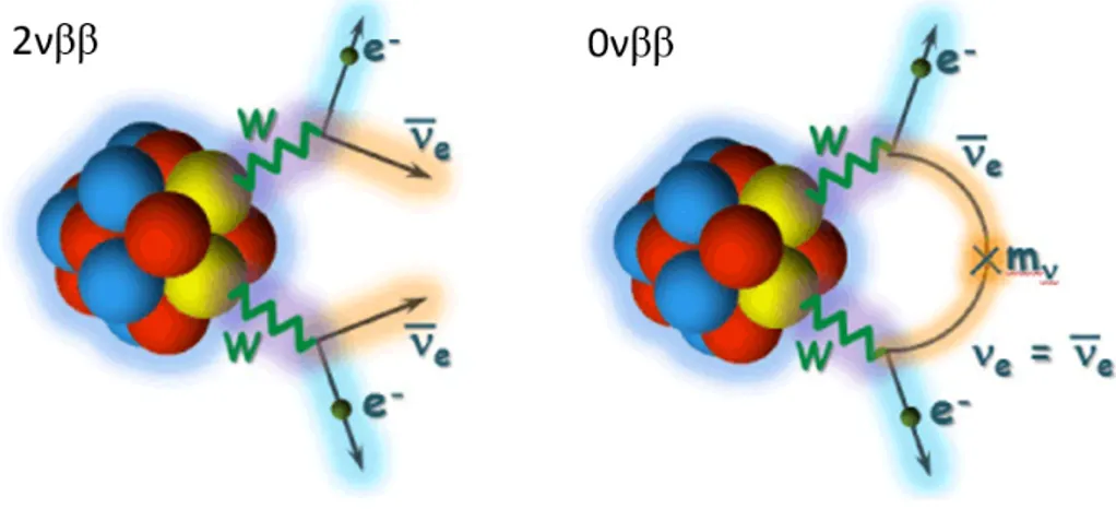
The double beta decay (ββ) is a rare nuclear process in which a nu-cleus of mass number A and atomic number Z, (A, Z), is converted into its isobar (A, Z ± 2). The literature distinguishes two types of mecha-nism for this process, named two-neutrino double beta decay (2νββ) and neutrinoless double beta decay (0νββ) respectively (Fig. 1.1).
The two-neutrino double beta decay mode is allowed by the Standard Model of elementary particles and it does not impose special require-ments on the neutrino properties. The process, observed for more than ten nuclei [10, 11], occurs irrespective of whether the neutrino is a
Majo-Figure 1.1: 2νββ and 0νββ on the left and on the right respectively. Taken from wwwkm.phys.sci.osaka-u.ac.jp.
rana or a Dirac particle and irrespective of whether it has a mass or not. The possible 2νββ decay modes are:
(A, Z) −→ (A, Z + 2) + 2e−+ 2 ¯νe (ββ−) (1.1.1)
(A, Z) −→ (A, Z − 2) + 2e++ 2νe (ββ+) (1.1.2)
(A, Z) + 2e− −→ (A, Z − 2) + 2νe (ECEC) (1.1.3)
(A, Z) + e− −→ (A, Z − 2) + e++ 2ν
e (ECβ+) (1.1.4)
The 2νββ is a second-order weak process, resulting in an extremely slow decay rate, namely the slowest process ever observed in nature, with half-lives of the order of 1018− 1022 years [12].
Therefore, the isotopes candidate for experimental observation of 2νββ are even-even nuclei for which the single beta decay is energetically for-bidden or suppressed by large change in angular momentum.
In the 0νββ process, that has never been observed, only electrons would be emitted:
(A, Z) −→ (A, Z + 2) + 2e− (ββ−) (1.1.5) (A, Z) −→ (A, Z − 2) + 2e+ (ββ+) (1.1.6) (A, Z) + 2e− −→ (A, Z − 2) (ECEC) (1.1.7) (A, Z) + e− −→ (A, Z − 2) + e+ (ECβ+) (1.1.8)
The 0νββ process is forbidden in the Standard Model, since the lepton number conservation is violated by two units, and its observation would thus points towards the existence of physics beyond the Standard Model. This process can occur only if neutrino and antineutrino must be indis-tinguishable and, as a consequence, the neutrino must be a Majorana particle. In this scenario, the antineutrino emitted at one vertex can be absorbed as a neutrino at the other vertex, as shown in the process scheme in Fig. 1.1 on the right. In addition to the Majorana equivalence of neutrino and antineutrino, a non-zero neutrino mass is required to flip
the helicity since the antineutrino is right-handed and the neutrino is left-handed.
The rate of 0νββ process Γ0ν can be factorized as the phase-space factor
G0ν, the nuclear matrix element M0ν and the effective Majorana mass
< mββ > [13]:
Γ0ν = [T1/2]−1 = G0ν· |M0ν|2 · | < mββ > |2 (1.1.9)
The information concerning the neutrino mass is contained in < mββ >:
< mββ >= 3
i=1
Uei2 · mi (1.1.10)
where Uei represents the Pontecorvo-Maki-Nakagawa-Sakata mixing
ma-trix [14, 15], that describes the mixing between the neutrino mass eigen-states and the neutrino flavor eigeneigen-states, and mi are the different
neu-trino mass eigenvalues.
In order to obtain information on < mββ > from the 0νββ rate
measure-ment, the knowledge of G0ν and M0ν is essential.
G0ν is proportional to the 5th order of the decay Q-value and can be
accurately calculated as explained in reference [16]. As a consequence, any uncertainty on the nuclear matrix element M0ν reflects directly on
the evaluation of < mββ >.
| M0ν|2 is the transition amplitude from the initial φi to the final φf
nuclear states of the ββ process through the 0νββ decay operator ˆO0νββ: |M0ν|2 = | < φf| ˆO0νββ|φi > |2 (1.1.11)
Since the ββ decay process involves transitions in atomic nuclei, nuclear structure issues must be also accounted for, in order to describe the NME. The evaluation of the NMEs is presently limited to state-of-the-art model calculations based on different methods, e.g. Quasi-particle Random Phase Approximation (QRPA), large scale shell-model, Interacting Bo-son Model (IBM), ab-initio, Energy Density Functional (EDF) [17–22].
Despite the calculations are constrained by high-precision experimental information from single charge exchange reactions, transfer reactions and electron capture, discrepancy factors higher than two are currently re-ported in literature [23]. The evaluation of the nuclear matrix element is a challenge in nuclear theory due to the complicated nuclear many-body nature of the problem.
1.2
The NUMEN project
NUMEN at INFN-LNS proposes cross section measurements of heavy ion induced Double Charge Exchange (DCE) reactions toward the deter-mination of the nuclear matrix elements, present in the expression of the 0νββ rate.
Hereinafter, an overview of the research project is presented. Detailed information about the project can be found in Ref. [2].
The DCE reactions are characterized by the transfer of two charge units, leaving the mass number unchanged, and they can proceed by a sequen-tial nucleon transfer mechanism or by meson exchange.
Despite the 0νββ decay and heavy ion DCE reactions are mediated by dif-ferent interactions, they present a number of similarities, such as the ini-tial and final nuclear states and the mathematical structure of the transi-tion operators. The descriptransi-tion of NMEs for DCE and 0νββ presents the same level of complexity but the DCE reaction study provides the great advantage to allow one to obtain experimental information on NMEs in laboratory controlled conditions.
The main characteristic of heavy ion induced nuclear reactions is the large number of final channels related to a large value of energy and angular momentum introduced by the heavy projectile into the initial reaction channel. In this scenario, the measurement of DCE high-resolution en-ergy spectra and accurate absolute cross sections at very forward angles (included 0◦) is crucial to identify the transitions of interest [17, 24].
The simultaneous measurement of the other reaction channels is funda-mental in order to isolate the direct DCE mechanism from the competing multi-nucleon transfer processes.
Modern high resolution and large acceptance spectrometers play a key role to extract information on NMEs from DCE reactions since they allow one to effectively face the main experimental challenges, that the early studies of heavy ion induced double charge exchange reactions failed to overcome. In literature a lack of data persists because of the technical difficulties to measure very low cross sections at zero degrees and the consequent poor yields in the measured energy spectra and angular dis-tributions [25–27].
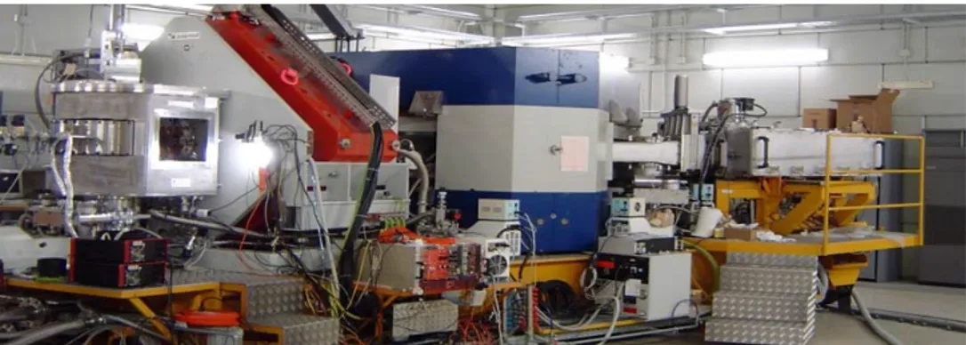
In order to achieve its goal, NUMEN will perform its experiments using the facility already installed at INFN-LNS, composed by the Supercon-ducting Cyclotron and the MAGNEX spectrometer [28], a modern high resolution and large acceptance magnetic system characterized by high resolution in energy, mass and angle, shown in Fig. 1.2.
NUMEN aims to carry out a series of experimental campaign in order to extract data-driven information on the nuclear matrix elements for the possible candidates to the 0νββ, indicated by the neutrino scientific community, i.e. 48Ca, 76Ge, 76Se, 82Se, 96Zr, 100Mo, 106Cd, 110Pd, 116Cd, 110Sn,124Sn,128Te,130Te,130Xe,136Xe,148Nd,150Nd,154Sm,160Gd,198Pt.
Figure 1.2: A view of MAGNEX spectrometer at Laboratori Nazionali del Sud in Catania.
The first campaigns of experiments are foreseen in sinergy with the NURE (NUclear REactions for neutrinoless double beta decay) project [29], a shorter time scale project correlated to NUMEN. It has been se-lected for receiving funding for 5 years in the call Starting Grant 2016 of European Research Council (ERC).
A pilot experiment was performed at INFN-LNS with the aim of verifying the feasibility of the technique proposed by NUMEN to access the NMEs [17]. In such an experiment, the 40Ca(18O,18N e)40Ar DCE reaction was
studied using a 18O beam accelerated by the LNS Superconducting Cy-clotron to the final kinetic energy of 270 MeV and detecting the ejectiles by means of MAGNEX.
The experiment demonstrated that high resolution and statistically sig-nificant experimental data can be measured for DCE processes but, for a systematic study of the many candidates for 0νββ decay, important experimental limitations need to be overcome. This implies substantial changes in the technologies of the MAGNEX spectrometer and the up-grade of the existing INFN-LNS accelerator facility.
The (18O,18N e) reaction will be used as a probe for the ββ+ transitions and the (20N e,20O) or the (12C,12Be) reaction for the ββ−, with the aim
of exploring the DCE mechanism in both directions.
The CS will provide the required beams, namely 18O, 20Ne and 12C , at energies ranging from 15 MeV/amu to 70 MeV/amu.
The choice of the target isotopes to be used in the NUMEN experiments represents a compromise between the interest of the scientific community to specific isotopes and related technical issues. The main constraints are the possibility of separation of the ground state-to-ground state transi-tion from that to the first excited state of the residual nucleus in the measured excitation energy spectra and the availability of thin uniform target of isotopically enriched material.
for-ward angles mainly depends on three independent factors, namely the intrinsic energy resolution of the MAGNEX spectrometer δE/EM AGN EX ( ≃ 1/1000 FWHM), the energy spread of the CS accelerated beam δE/ECS and a contribution due to the straggling and energy loss of the beam and ejectiles in the target δE/ET ARGET. The total energy resolu-tion is thus:
δE ∼
(δEM AGN EX)2+ (δECS)2+ (δET ARGET)2 (1.2.1)
The request of high resolution of the measured energy spectra implies challenging requests on the target characteristics and on the energy spread of the extracted beams from the INFN-LNS Superconducting Cyclotron. NUMEN requires an energy resolution of the CS beams equal to 1/1000 FWHM. The δE/ET ARGET depends, for a given beam, on the target ma-terial and thickness and on its uniformity.
Beside the high energy resolution challenge, the exploration of nuclei of interests for 0νββ is also challenging for the following reasons, that imply low process yields:
- Low cross section of the DCE reactions;
- The (18O,18N e) reaction, investigated in the pilot experiment, is particularly advantageous but this reaction is ββ+ kind, instead most of the research on 0νββ decay is of the ββ− kind.
None of the reactions of ββ− kind looks like as favourable as the (18O,18N e). For example, the (18N e,18O) requires a radioactive beam, which cannot be available with enough intensity;
- In some cases, e.g. 136Xe or 130Xe, gas or implanted target will
be necessary. They are normally much thinner than solid targets obtained by evaporation and this implies consequent reduction of the collected yield;
- The detection in coincidence of gamma rays from the de-excitation of the populated states will be necessary for the cases for which the energy resolution is not enough to separate the ground from the excited states in the final nucleus in the measured excitation energy spectra. As consequence, a yield reduction is expected for these cases.
Due to the low process yields, high intensity beams are necessary for the DCE reaction study in order to collect significant statistics of data in a reasonable time. The challenge proposed by NUMEN and by the NURE projects is to measure rare nuclear transitions under a very high rate of heavy ions produced by the beam-target interaction.
The pilot experiment demonstrated that higher beam intensity with re-spect to the present one is mandatory for the NUMEN reaction study. This goal can be achieved by a substantial upgrade of the CS in order to overcome the present limit on the maximum beam power delivered by the CS (≃ 100 W). By changing the beam extraction mode, we plan to extract a beam power from the CS in the range 1 − 10 kW, correspond-ing to currents of the order of 1013 − 1014 pps for the NUMEN energy
range. The increase of the beam intensity implies first of all the develop-ment of cooled isotopically enriched thin target, able to resist to the high power dissipated by the interaction of the intense beams with the target material. Furthermore, also the upgrade of the MAGNEX spectrometer is foreseen especially to take into account the higher rate of incoming ejectiles on its detection system. In addition, as above-mentioned, the use of a gamma detector system close to the target is expected for the discrimination of nearby energy states.
Due to the expected high beam power extracted by the CS, the radiopro-tection issues must be considered. A careful evaluation of radiation levels along the new dedicated beam tranport line, is mandatory, together with the study of its effects on detectors, electronics and various equipment in
the MAGNEX experimental hall.
1.3
New research in nuclear physics and
astrophysics using intense radioactive
ion beams
The use of Radioactive Ion Beams (RIBs) in the nuclear physics exper-iments has been allowing since last decades to investigate many properties of unstable nuclei. The RIBs can be produced by the Isotope Separation On Line (ISOL) [30] and the in-flight [31] production techniques.
Many facilities for RIBs production are present worldwide, one of which is installed at INFN-LNS in Catania, and many others are still under construction [32–34].
The FRIBs@LNS (in Flight Radioactive Ion BeamS at LNS) facility [35] has been operating in Catania for the last 15 years allowing one to carry out nuclear physics experiments for the investigation of the properties of short-lived nuclear species. The RIBs are produced, using the in-flight technique, by fragmentation of a fast projectile on a thick Beryllium made target. The CS has a key role within the FRIBs facility because it delivers the accelerated primary beams, in particular 12C, 20Ne, 40Ar
and 58Ni ions at energies between 40 MeV/amu and 60 MeV/amu. The reaction processes occur close to the CS exit where the thin target is placed.
Since a multitude of nuclei, mainly stable, are produced after the inci-dence of the primary beam on the thin target, a magnetic analysis is needed to select the RIBs of interest according to the specific nuclear physics study to be carried out. In the FRIBs@LNS facility, the pro-duced exotics fragments are selected, transported and focused by the same optical elements of the beam line normally used for the transport of the beams to the LNS experimental halls.
As shown in Fig. 1.3 below, the fragment separator consists on two 45◦ bending dipole magnets D1 and D2, three quadrupoles triplets Q1-Q3, Q4-Q6 and Q7-Q9 and two sextupoles correctors S4, S9 near the quadrupoles Q4, Q9.
The bending dipole magnets are used for isotope selection according to the magnetic rigidity, the quadrupoles allow one the beam focusing. A degrader can be placed at the intermediate focus.
The produced RIBs are delivered to many experimental halls, housing detectors as CHIMERA [36], FARCOS [37], MAGNEX [38].
Figure 1.3 above shows the 3D layout of the LNS with the beam lines and the experimental halls.
Since the magnetic analysis does not allow one to separate isotopes with the same mass-to-charge ratio and, in addition, it has always a fi-nite dp/p acceptance (≃ 1% in the case of FRIBs), an event-by-event identification (tagging) of each nucleus of the secondary beam, before it interacts with the secondary target, is performed in the beam line. The tagging technique combines Time of Flight (ToF) and energy loss ∆E measurements, with detectors placed in the beam line and close to the scattering chambers in the experimental halls. The use of the ∆E-ToF method has the advantage of not stopping the incoming ions and to modify as less as possible their characteristics.
The investigations on the properties of unstable nuclei have been always limited to nuclei not far away from the stability valley, e.g. 10Be, 16C, 18Ne,68Ni, with beam intensities of about 104−105 pps. Typical energies
of the RIBs produced are between 20 MeV/amu and 45 MeV/amu. The limit on the maximum beam power delivered by the CS and the radio-protection issues related to the fragment separator shielding do not allow to obtain higher intensities for these nuclei and, in addition, to perform investigations on nuclei far away from the stability valley, being the yields for very exotic nuclei are very low. Nevertheless,
impor-Figure 1.3: Above: 3D layout of the LNS laboratories with the beam lines and the experimental halls. Below: layout of the Fragment Separator used in the FRIBs project.
tant physics cases have been investigated by using the RIBs delivered by FRIBs@LNS [3].
In the perspective of the upgrade of INFN-LNS Superconducting Cy-clotron, a new FRAgment Ion SEparator (FRAISE) [3] is now under study at INFN-LNS. More detail about the status of the FRAISE study are presented in Chapter 3. The expected higher beam power for primary
beams delivered by the CS would be used to produce very intense RIBs also for ions very far from the stability valley. Consequently, progress in production method of the RIBs coupled with advances in experimental techniques and detection device could open new interesting perspectives of research at INFN-LNS in the field of the exotic nuclei, interesting clus-ter physics, nuclear structure and isospin physics studies. With FRAISE, it is also foreseen to extend the use of RIBs towards the low energy do-main (few MeV/amu) for nuclear astrophysics studies [3].
1.4
The improvement of the INFN-LNS
Su-perconducting Cyclotron performances
The INFN-LNS Superconducting Cyclotron has been operating in axial injection mode for about 18 years delivering beams of various ion species and energies with currents up to few hundred of enA.
As described in Chapter 2, the present beam extraction system is com-posed of two electrostatic deflectors followed by a set of magnetic chan-nels. Unfortunately, the accelerator compactness limits the extraction efficiency at about 60% and consequently the maximum beam power that can be delivered by the CS.
Turn separation is a critical aspect when the beam extraction occurs by means of electrostatic deflectors and especially in compact cyclotrons, as in the case of the CS. The lack of separation between last turns in the INFN-LNS cyclotron implies a beam loss on the first electrostatic deflec-tor. The maximum beam power that the CS can deliver is also limited by the thermal issues of the first electrostatic deflector. Indeed, although it is water cooled, the electrostatic deflector is not reliable when the dis-sipated beam power exceeds 100 W. As a consequence, the extraction of beam power up to 10 kW is not feasible using the present extraction system.
The stripping extraction seems to be a valid alternative to increase the extraction efficiency for the ion species with mass number A < 20 and energies higher than 15 MeV/amu. For these ions and energies, the strip-ping extraction would allow one to achieve extraction efficiencies higher than 99% [39]. However, the new extraction method would be very effi-cient also for medium mass nuclei with mass number A ∼ 40, that are of interest for RIBs production.
The extraction by stripping of the light-medium ion beams for NUMEN and RIBs production, together with the increase of the injection effi-ciency, would allow one to extract 100 times higher beam power than the present one.
Table 1.1 shows the expected beam currents and beam power at the exit of the upgraded INFN-LNS Superconducting Cyclotron for some of the ion beams of interest for NUMEN. Conservative values of the beam cur-rents delivered by the ion source and injected and accelerated by the cyclotron are also given.
In order to extract by stripping ion beams, a significant upgrade of the CS is foreseen. Accurate simulation studies, followed by changes of the technologies currently used and the development of new ones, are mandatory in order to transform the CS in a high intensity cyclotron. Hereinafter, a brief description of the project of the CS upgrade is given. A detailed description of it is presented in Chapter 3.
The main changes in the INFN-LNS Superconducting Cyclotron will con-sist in the replacement of the existing cryostat and the superconducting coils with new ones. The coils will have the same form factors of the present ones but smaller height to significantly increase the vertical gap available for the new extraction channel, that it is foreseen to be ma-chined and used for the stripping extraction.
At the same time, the CS has to continue to deliver all the beams presently accelerated in order to satisfy the requests of the already
exist-ing research projects at INFN-LNS.
For this reason, the CS will be equipped with two extraction systems and two extraction channels, in particular, the present one to be used for the extraction by electrostatic deflectors and the new one for the stripping extraction.
The expected energy spread of the beams after the stripping extraction is around ±0.3% FWHM, value exceeding the stringent request of the NUMEN research project. A new transport line to be used as an energy selector to reduce the beam energy spread as well as a fragment in-flight separator for the production of radioactive ion beams is under study at INFN-LNS.
Ion Energy Isource Iinj Iextr Iextr Pextr
MeV/amu eµA eµA eµA pps Watt
12C4+ 45 400 60(4+) 90(6+) 9.4 · 1013 8100 12C4+ 60 400 60(4+) 90(6+) 9.4 · 1013 10800 18O6+ 29 400 60(6+) 80(8+) 6.2 · 1013 5220 18O6+ 45 400 60(6+) 80(8+) 6.2 · 1013 8100 18O6+ 70 200 30(7+) 34.3(8+) 2.7 · 1013 5400 20Ne7+ 28 400 60(7+) 85.7(10+) 5.3 · 1013 4800 20Ne7+ 70 400 60(7+) 85.7(10+) 5.3 · 1013 12000
Table 1.1: Expected beam currents and power delivered at the exit of the upgraded Catania cyclotron for some of the ion beams of interest for the NUMEN research project.
Chapter 2
The INFN-LNS
Superconducting Cyclotron
The construction of the LNS Superconducting Cyclotron (CS) was funded by INFN (Istituto Nazionale di Fisica Nucleare) in 1981.
The CS was born from the collaboration between two INFN laboratories, LASA in Milan and LNS in Catania. In particular, the design of the ac-celerator and the construction of its main components were performed at LASA [40] while the cyclotron was assembled in its final location in Catania in 1990 [41, 42]. The CS was at that time the first cyclotron to have travelled more than 1000 km from the place of conception to its final site.
During the first four years of operation, the cyclotron worked as a booster of the 15 MV Tandem accelerator, previously installed at INFN-LNS [43]. The Tandem beams were radially injected into the cyclotron, where a stripper foil, located on a hill, increased the charge state of the ions before the acceleration in the CS.
The first beam extracted from the CS,58Ni16+with a final kinetic energy
equal to 30 MeV/amu, was available in the experimental rooms of the LNS laboratory in June 1995 and the first nuclear physics experiment was successfully performed the following month [44].
in-jection mode and, since then, the CS has been working in stand alone mode.
The main reason behind the introduction of the axial injection was the possibility to increase the intensity of light ion beams using an external ECRIS (Electron Cyclotron Resonance Ion Source) in order to give the CS the role of primary accelerator for the production of radioactive ion beams in the frame of the EXCYT (EXotics with CYclotron and Tan-dem) project at INFN-LNS [45].
This chapter is devoted to present the main features of the INFN-LNS Superconducting Cyclotron.
2.1
Main characteristics
The INFN-LNS cyclotron is a compact superconducting cyclotron characterized by the three-fold rotational symmetry.
It is a multi-particle variable energy cyclotron, able to accelerate ions from the lightest ones up to Uranium, mainly used for nuclear physics research.
Although the CS is not able to accelerate proton beams, since 2002 pro-tons has been used for radiotherapy. Indeed, H+2 molecules are acceler-ated and extracted and then broken into two protons when crossing a stripper foil placed in the beam line out of the cyclotron.
The isochronous magnetic field, in the range of 2.2-4.8 T, is produced by the combined contribution of two superconducting main coils, three fully saturated iron spiralled pole sectors, the yoke and twenty trim coils wound around each hill.
The CS was the first cyclotron in Europe to use superconducting coils to generate the main field. The trim coils are used for the fine-tuning of the isochronous magnetic field for the acceleration of many ions with different final kinetic energies.
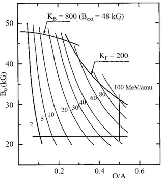
mag-netic field at the extraction and the extraction radius) is 800 and the focusing limit KF (depending on the flutter and on the spiral angle) is
200. For any ion charge-to-mass ratio Q/A, KB and KF set a limit on
the maximum kinetic energy per nucleon T /A. In particular, for a given Q/A, the maximum T /A is the smallest between the following values:
T /A = KB· (Q/A)2 (2.1.1)
T /A = KF · (Q/A) (2.1.2)
The operating diagram of the CS in the (B0, Q/A) plane, where B0 is the
centre magnetic field, is shown in Fig. 2.1. The bending KBand focusing
KF limits are shown, together with lines of constant kinetic energy per
nucleon. The minimum operating field B0 is 22 kG, limit imposed by the
resonance νr+ 2 · νz= 3, where νr and νz are respectively the radial and
Figure 2.1: Operating diagram of the CS in the (B0, Q/A) plane, where B0 is the
centre magnetic field. Bending KB, focusing KF and low field limits are
indicated. Constant kinetic energy per nucleon lines are also shown. The present limit on the maximum energy is 80 MeV/amu and not 100 MeV/amu.
vertical betatron oscillation frequencies [46].
At low Q/A and T /A, the operating diagram is bounded by the bending limit KB, while the focusing limit becomes more restricting at high Q/A
and T /A.
The CS was designed for energies between 100 MeV/amu for fully stripped light ions and down to 20 MeV/amu for heavy ions like Uranium. Any beams with an appropriate charge-to-mass ratio Q/A and desired kinetic energy T /A, that lie within the diagram, could in principle be ac-celerated. Actually, the limit on the maximum energy is lower than 100 MeV/amu due to components of the CS, like the electrostatic deflectors, that prevent the cyclotron from achieving the best performance. The actual maximum energy allowed is 80 MeV/amu for fully stripped light ions.
Harmonic numbers h equal to 1, 2, 3 and 4 are available for acceleration in a wide range of energy. The synchronism condition is given by:
fRF = h · f0 (2.1.3) with f0 = ω0 2π with ω0 = qB0 m (2.1.4)
where fRF is the frequency of the RF accelerating voltage and f0 is the
ion orbital frequency. In Eq. (2.1.4) q is the ion charge, m is the par-ticle mass and B0 is the isochronous value of the magnetic field in the
cyclotron centre.
Figure 2.2 shows the ion energy per nucleon as a function of the RF fre-quency, for the 1st, 2nd, 3rd and 4th harmonic modes of acceleration. The
operating frequency range of the RF cavities is 15-48 MHz.
The CS has almost always worked in harmonic h = 2 in order to obtain beam energies in a wide range, between 8 MeV/amu (≃ Coulomb bar-rier) and 100 MeV/amu. Only the energies in the range 2-8 MeV/amu, lower than the Coulomb barrier, are excluded, as shown in Fig. 2.2 .
Figure 2.2: Energy per nucleon as function of the RF frequency for the harmonics equal to 1, 2, 3 and 4. The operating frequency range of the RF cavities of the CS is 15-48 MHz.
The accelerating system consists of three λ/2 coaxial resonators loaded with 60◦dees placed in the valleys. Because of the presence of the cryostat and the small distance between the superconducting coils, the inductive parts of the RF cavities extend vertically. The central region, designed before 2000, was optimized to work in 2ndharmonic mode of acceleration.
The beams are generated by two ECR ion sources and axially injected into the median plane through a spiral inflector.
The present extraction system consists of two electrostatic deflectors, placed on consecutive hills, and a set of passive magnetic focusing chan-nels.
The main cyclotron parameters are listed in Table 2.1.
Figure 2.3 shows on the left the sketch of the cyclotron with its main components. On the right of Fig. 2.3 a picture of the INFN-LNS Super-conducting Cyclotron is presented.
Figure 2.3: The INFN-LNS Superconducting Cyclotron. On the left, the sketch of the cyclotron with its main components. On the right, a picture of the cyclotron.
Bending limit KB 800
Focusing limit KF 200
Center field [min-max] 22-48 kGauss
Pole radius 900 mm
No¯ of sectors 3
Superconducting coils 2 pairs No¯ of trim coils 20 (for sector)
No¯ of dees 3 (in valleys)
RF frequency range 15-48 MHz
Harmonics h 1, 2, 3, 4 (only 2 used) Table 2.1: Main parameters of the INFN-LNS Superconducting Cyclotron.
2.2
The magnetic structure
As in all compact superconducting cyclotrons, the main magnetic field of the CS is generated by three different structures:
- the pole expansion;
- the superconducting coils; - the yoke.
The trim coils give only a small contribution (of the order of 0.1-1 %) to the total magnetic field but very important for the isochronism.
The superconducting coils, together with the yoke, provide the main magnetic field contribution, which is variable for different beams and they are used for the ion confinement. Instead, the pole expansion gives the azimuthal modulation used for the vertical focusing of the accelerated beams. The principle of the AVF (Azimuthal Varying Field) cyclotron was proposed for the first time in 1938 by L. H. Thomas [47] to overcome the problem of the insufficient vertical focusing in the classical cyclotron. The vertical focusing is further increased in the CS by the spiral shape of the iron sectors.
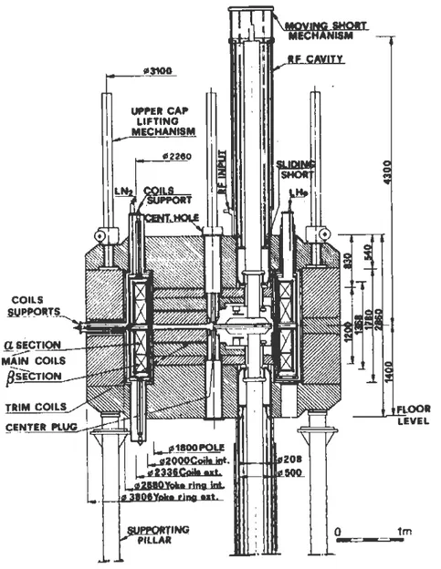
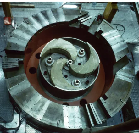
A view of the vertical cross section and median plane of the CS accelerator is presented in Fig. 2.4 and 2.5 respectively. Fig. 2.6 shows a picture from the top of the CS magnet.
Hereinafter, a description of the main components of the CS magnetic system is presented. More detail can be found in Ref. [46, 48].
2.2.1
The iron structure
The main parameters of the CS magnet are listed in Table 2.2. The full magnet weight, including the sectors, is 176 tons.
The yoke is cylindrical with the inner and outer radius equal to 1340 mm and 1903 mm respectively. It is composed of pieces of steel with
Figure 2.4: Sketch of the vertical cross section of the INFN-LNS Superconducting Cyclotron. All dimensions are in mm.
very good magnetic properties (carbon content < 0.01 %): the upper and lower cap and the return yoke to reduce the stray magnetic field. The pole has a radius equal to 900 mm and extends up to 600 mm from the median plane. The minimum hill gap is 86 mm and the maximum valley gap is 916 mm.
Figure 2.5: Sketch of the CS median plane. All the radial penetrations are visible.
The azimuthal width of the hills is 33◦ at the radius of 90 mm, beyond which it increases as the radius rises, achieving the maximum value of 52◦ in the region immediately before the pole radius. Also the spiral constant increases with rising radius, from 1/45.7 rad/cm to 1/31.4 rad/cm. Each hill is composed of two parts 200 mm thick in order to provide space for winding the twenty trim coils around the upper part. The part of each hill closer to the median plane has rounded edges in order to facilitate the winding of the trim coils. A picture of the pole sectors with the three split hills is presented in Fig. 2.7.
In each valley various holes are provided for the RF cavities and for the leads of the trim coils, as shown in Fig. 2.5.
Figure 2.6: Picture from the top of the magnet of the CS.
Rotational symmetry Three-fold
Steel Carbon content < 0.01%
Total weight 176 tons
Yoke inner radius 1340 mm
Yoke inner radius 1903 mm
Yoke full height 2860 mm
Pole radius 900 mm
Minimum hill gap 86 mm
Maximum valley gap 916 mm
Figure 2.7: Pole sectors of the CS. Each hill is split in two parts. The upper part has rounded edge in order to facilitate the winding of the trim coils around it. The picture was taken in Milan before the installation of the CS in Catania.
iron imperfections in the pole sector and to produce the desired average magnetic field. The shim on the valley between the radii 875 mm and 900 mm, together with the inner wall of the vacuum tank (a ring with a 24 mm thickness and a vertical extension up to 60 mm from the median plane), are such that the radius of the isochronous orbits is very near to the pole radius.
A vertical central hole of 70 mm diameter is provided for the beam axial injection. The hole increases to a 250 mm diameter through the pole and the yoke to provide more room for the buncher, placed at 500 mm from the median plane. A centre iron plug, consisting of a cylindrical part and a hill part 33◦ wide is present to prevent that the flutter goes to zero quickly and then it provides some vertical focusing.
2.2.2
The superconducting coils
The isochronization of the magnetic field, for different ions to be ac-celerated to different final kinetic energy, is mainly obtained with the excitation of the two superconducting coils, since they produce up to 70 % of the total magnetic field while the contribution of the trim coils is only of the order of few hundreds Gauss.
The coils are subdivided into two independent sections so that their cur-rents can be varied in order to obtain the radial gradient adjustment of the isochronous field, necessary for the acceleration of any ion within the CS operating diagram.
Figure 2.8 shows the sketch of the vertical section of the CS upper coil. The coil section closest to the median plane is named α and the other one β. In order to achieve a magnetic field level close to 5 T and the proper radial field shape, the coils are placed as close as possible to the median plane and to the pole. The internal and external radii of the coils are 1000 and 1168 mm respectively and the minimum distance from the median plane is 62 mm.
These values were chosen taking into account the constraints imposed by the radial penetrations needed for the extraction elements.
The size, position and sections subdivision of the coils were opportunely chosen, together with the optimization of the iron field, during the design study of the CS, in order to minimize the trim coil power throughout the operating range of the cyclotron. A low trim coil power is needed to reduce residual field errors and consequently make negligible the oscilla-tions in the phase curve and of the focusing frequencies for the accelerated ions.
The minimization method is based upon the selection of two appropriate ions which can be thought as representative of the extreme isochronous fields required, in the operating range of the CS.
as the superscript i, can be written as:
Bisoi (r) = Biron(r) + Fα(r)Iαi + Fβ(r)Iβi + N
k=1
Fk(r)Iki + ϵ
i(r) (2.2.1)
where Biron(r) is the magnetic field generated by the iron configuration,
Fα(r), Fβ(r) and Fk(r) are the form factors of the main coil sections and
of the kth trim coil (N coils total) while Iα, Iβ and Ik the corresponding
currents and ϵ(r) is the field error with respect to isochronous field. If one evaluates equation 2.2.1 for the least and most relativistic particles in the operating range of the cyclotron, and then subtracts the two equations, it gets:
∆Biso(r) = Fα(r)∆Iα+ Fβ(r)∆Iβ+ N
k=1
Fk(r)∆Ik+ ∆ϵ(r) (2.2.2)
where Biron(r) is assumed to be equal for the two ions.
An ordinary least squares fitting procedure of the quantity
r[∆ϵ(r)] 2
permits to find the minimizing following conditions:
ϵ1(r) + ϵ2(r) = 0 for every radius (2.2.3) Ik1+ Ik2 = 0 for every trim coil (2.2.4) More information can be found in Ref. [49].
The minimization of the trim coil power imposes that the current den-sity in the section β must be negative for the acceleration of fully stripped ions. The current density Jain the α section varies between +1500 A/cm2
and +3500 A/cm2, the current density Jb in the other section goes from
-1500 A/cm2 to +3500 A/cm2. Since the use of high currents leads to
strong axial forces on the coils, also of opposite sign for different sets of currents, a careful analysis of the forces and stresses on the coils was carried out during the design study of the CS. The α section is always attracted toward the median plane, the β section is pushed away from the median plane for negative current densities. As shown in Fig. 2.8, a
set of Cu-Be tie rods are used to prevent the β coil axial lifting but also to produce a sufficient pre-load of the α section.
The axial suspension of the coils is made with three pairs (upper -lower) of 16 mm diameter Ti-alloy rods, of about 1 m length. The coils are wound with the double pancake technique and consist of 38 turns of 26 layers in the α section and 18 layers in the other one [50].
The maximum current density is +3500 A/cm2 for both sections,
corre-sponding to a total of 6.5·106 At. The main coils characteristics, included
the cable features, are listed in Table 2.3.
In order to maintain the coils in the superconducting state, they are in a liquid helium bath at atmospheric pressure (T = 4.2 K).
The Helium vessel, where the superconducting coils are placed, is made of stainless steel and it is surrounded by a liquid nitrogen cooled
Max Ampereturn 6.5 · 106 At Max engineering current density 3500 A/cm2
Internal radius 1000 mm
External radius 1168 mm
Minimum distance from MP 62 mm
Height of α section 364 mm
Height of β section 252 mm
Turns/pancake 38
Layers in α section 2 · 13
Layers in β section 2 · 9
Cable type Nb-Ti insert in Cu cable Overall Cu-Sc. ratio in the cable 20:1
Cable dimensions 13 · 3.5 mm2
Total conductor length 22.6 Km
Table 2.3: Main parameters of the CS coils.
mal shield and by the vacuum chamber. The outer wall of the vacuum chamber iron made, so it is part of the iron circuit. The coil position is fixed by axial and radial tie rods placed every 120◦.
2.2.3
The trim coils
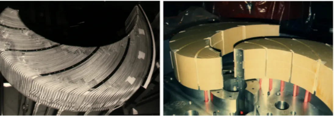
The twenty trim coils, wound around the upper part of each hill, are divided into five groups, separated by radial spacers and each one com-posed by four coils, as shown in Fig. 2.9 on the left. The trim coils are numbered starting from the CS centre. The coils, indicated by the num-bers 3, 4, 19 and 20, are named harmonic coils, because of their harmonic contribution to the total magnetic field. The first two harmonic coils are placed immediately outside the central region for the beam centring, the
other ones in the extraction region.
All the trim coils are water cooled and covered by a thin isolating coat-ing, as shown in Fig. 2.9 on the right. The maximum carried current is 500 A.
The squared cable section is not the same for all the trim coils, in par-ticular the harmonic coils closest to the centre have a smaller cable sec-tion (side=3/16”, hole diameter = 1/8”) with respect to the other ones (side=1/4”, hole diameter = 3/36”) in order to reduce their azimuthal extent around the hill in the cyclotron center.
Figure 2.9: Correction trim coils in the INFN-LNS Superconducting Cyclotron. Five groups of trim coils, each one composed by four coils, are visible on the left. The thin isolating material coating the trim coils is visible on the right.
2.3
The extraction system
When the ions have reached their final kinetic energy, they are ex-tracted from the CS by means of two electrostatic deflectors placed on two consecutive hills.
A horizontal constant electric field is present between the two electrodes of each electrostatic deflector. The beam is deflected when it enters the extractors, as shown in Fig. 2.10, because of the electric force acting on the beam particles opposite to the magnetic force inward directed. The sketch of the CS electrostatic deflectors is presented in Fig. 2.11
Figure 2.10: Sketch of the extraction from a cyclotron by electrostatic deflector. The electric field between the HV electrode and the septum, which is at zero potential, is radial.
on the left. The inner electrode of each extractor, called the septum, is placed between the last and second to last turn. It is on ground potential so that the inner orbits in the cyclotron are not affected. The distance between the septum and the other electrode is 6 mm.
The septum of the first electrostatic deflector is very thin (thickness of the order of 0.3 mm) to minimize the beam losses on the septum itself. It is water cooled and, furthermore, the beginning of the septum is V-shaped, as shown in Fig. 2.11 on the right, in order to better distribute the heat due to beam losses.
The other electrode of each extractor is on negative high potential, being that all the accelerated ions have a positive charge. The maximum volt-age applicable is about –60 kV, corresponding to a limit on the electric field equal to 100 kV/cm.
The septum, screwed to the liners, is Tungsten made whereas the housing and the liners, surrounding the negative high voltage electrode, are made of OFHC copper.
Figure 2.11: On the left, the sketch of the CS electrostatic deflectors with their main components. The red star represents the beam passing between the sep-tum and the high negative voltage electrode. On the right, a photograph of the beginning of the first electrostatic deflector of the CS. The septum, screwed to the liners, is V-shaped in order to reduce the hit load from the beam.
field varies considerably from ion to ion, and the ions extracted at low and high magnetic field exhibit different orbit scalloping in the electrostatic deflectors [51]. In order to extract a large variety of ions with different energies, the CS electrostatic deflectors are radially movable over a range of about 30 mm. In addition, they are split in two parts of about same length connected by a swivel joint to adapt in shape to the different tra-jectories to be extracted. This solution is also adopted at MSU (Michigan State University) for the K500 cyclotron [52].
After passing the electrostatic deflectors, the ions enter into the fringing field of the magnet. In this region the beams are subject to a strong horizontally defocusing action, which is due to the negative gradient (in outward direction) of the magnetic field. In order to prevent the beam from diverging too much, passive magnetic focusing channels are placed along the extraction path, in particular inside the vacuum cham-ber and throughout the cryostat traversal. The first two magnetic chan-nels, named M1 and M2, immediately follow the electrostatic deflectors.
Other five magnetic channels, labelled M3, M4, M5, M6 and M7, are
through the cryostat traversal. Another magnetic channel, named M8, is
inserted in the yoke exit.
The magnetic channels are composed of three small iron bars which are magnetized by the main field of the cyclotron. Due to the different re-quirements on the field and on the radial focusing along the extraction path, the magnetic channels are not identical. Only the magnetic chan-nels from M3 to M7 have the same shape whereas the other ones are
differently designed. Fig. 2.12 shows the vertical cross section of all the magnetic channels.
The bars are shaped and arranged in such a way that the magnetic field produced by them has an approximately constant positive gradient in outward direction normal to the beam. This field shape counteracts the defocusing action of the fringing field of the magnet. As an example, Fig. 2.13 shows the magnetic field and transverse gradient created by the magnetic channel M1. Three iron bars, named C1A, C1B and C2, are
present to compensate the first harmonic perturbation due to the mag-netic channels from M1 to M7.
Since the median plane penetrations through the cryostat were drilled before the magnetic field measurements, two extra holes, named M2 bis
and M7 bis, were designed during the study of the extraction from the
CS as alternative positions for the magnetic channels M2 and M7
respec-Figure 2.12: Vertical cross section of the magnetic channels of the Catania cyclotron. All dimensions are in mm. The red dots represent the beam position.
Figure 2.13: Magnetic field and transverse gradient created by the magnetic focusing channel M1.
tively for the extraction of the more critical ions.
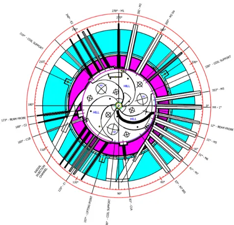
Figure 2.14 on the left shows the sketch of the CS median plane with all the elements of the extraction system. On the right, the penetrations in the yoke needed by the extraction system are shown.
The relevant parameters of the CS electrostatic deflectors are listed in Table 2.4.
The polar coordinate system assumed in Fig. 2.14 and in Table 2.4 is such that the polar angle θ increases for rotations in clockwise orienta-tion, starting from the reference axis defined in Fig. 2.14, corresponding to 0◦.
2.4
The injection system
As already reported in the introduction, in the year 2000 the radial in-jection was replaced by the axial inin-jection. This choice has permitted to
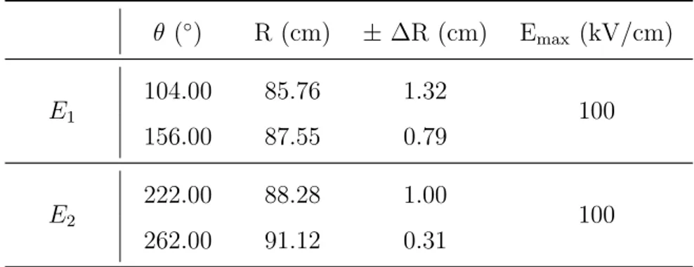
Figure 2.14: On the left, the sketch of the extraction system of the CS. On the right, the median plane view of the CS yoke with all the penetrations needed by the extraction system. The radial injection channel, no longer used, is also shown. The polar angle θ increases for rotations in clockwise orientation [51]. θ (◦) R (cm) ± ∆R (cm) Emax (kV/cm) E1 104.00 85.76 1.32 100 156.00 87.55 0.79 E2 222.00 88.28 1.00 100 262.00 91.12 0.31
Table 2.4: Main parameters of the electrostatic deflectors of the INFN-LNS Super-conducting Cyclotron: the initial and final azimuth, the average central ray position and the excursion around it at the two azimuths, the maxi-mum electric field. The polar angle θ increases for rotations in clockwise orientation [51].
improve the performance of the INFN-LNS Superconducting Cyclotron, in terms of both beam intensity and energy, and to extend the number of the ion species that the CS was able to accelerate.
Indeed, the EXCYT project required acceleration of light ion beams (from C to Ne) with higher intensity with respect to those obtainable using the CS as a booster of the 15 MV Tandem. Furthermore, since
the Tandem requires negative ions for first acceleration, only atoms with positive electron affinity could be used.
The first upgrade of the CS was made possible by means of the installa-tion in 1998 at INFN-LNS of a high performing superconducting Electron Cyclotron Resonance Ion Source, designed and constructed by INFN-LNS in collaboration with the CEA of Grenoble. This source, named SERSE, is currently operated at INFN-LNS and it is able to produce stable highly charged ion beams with higher intensities with respect to room temperature ion sources. In order to ensure the continuous opera-tion of the cyclotron, a second ECRIS with room-temperature magnets, named CAESAR, was also installed a few years later.
A detailed description of the CS ion sources and of their characteristics can be found in reference [53].
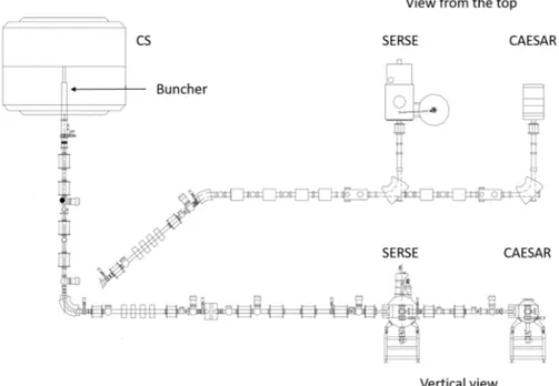
The axial injection mode implied the replacement of the stripper system with the axial injection system composed by the spiral inflector and cen-tral region. An injection line was also designed and constructed for the beam transport from the ion source to the spiral inflector, used for the 90◦ bending of the beam onto the median plane.
In this section, a description of the components of the CS injection sys-tem, including the two ion sources and the injection line, is presented.
2.4.1
The SERSE ion source
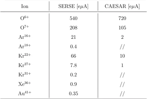
The SERSE superconducting ion source is one of the most performing sources among those currently used in the various worldwide laborato-ries, being able to produce totally stripped Argon ions (Ar18+) with a current of 0.2 µA and up to 2 µA of Xe36+ [54].
Figure 2.15 shows a picture of the SERSE ion source in its location at INFN-LNS. The plasma chamber is constituted by a 450 mm long alu-minium cylinder with 130 mm inner diameter, closed by the injection and extraction flange at the two ends.
The magnetic field is generated by three superconducting solenoids (en-abling axial plasma confinement) and by sextupole (en(en-abling radial plasma confinement). All the coils are made of a superconducting cable Nb-Ti made. The magnet cooling system uses a 1310 mm long cryostat with a 1000 mm diameter containing liquid helium (LHe) at the temperature of 4.2 K. The superconducting magnetic system generates a magnetic field of ∼ 2.7 T at microwaves injection, while magnetic field at extraction is ∼ 1.6 T. Maximum radial magnetic field generated by the hexapole is 1.6 T. So high values of confining magnetic field enable to improve plasma confinement and therefore to increase the maximum charge state the source can generate.
Nominal operating frequency of the SERSE source is 18 GHz. The use of two microwaves generators (usually a klystron and a Traveller Wave Tube (TWT)) enables to work in Two Frequency Heating (TFH), im-proving the source performance [55].
The extraction of ions takes place through a system of electrodes, with a total extraction voltage of around 20 kV (maximum applicable voltage is 25 kV).
Once extracted, the beam is focused by a solenoid, while a 90◦ analysis magnet selects the desired charge states as a function of Q/A.
2.4.2
The CAESAR ion source
The normal-conducting CAESAR ion source was funded in 1997 and installed in 1999 at LNS. The availability of a second ECRIS has allowed the continuous operations of the LNS accelerator facility, leaving SERSE free for developments [53, 56].
A picture of CAESAR source at the INFN-LNS is shown in Fig. 2.16. Normal conducting magnets generate a maximum magnetic field which overcomes 1.1 T either in injection and extraction region. Microwave power is produced by a klystron, operating in the range 14-14.5 GHz,
Figure 2.15: The SERSE ion source at INFN-LNS.