TUSCIA UNIVERSITY
DEPARTMENT OF AGRICULTURAL AND FORESTRY SCIENCES PhD course in
Agricultural and Forestry Engineering - XXVIII Cycle
EXPERIMENTAL ANALYSIS AND SIMULATION OF BIOMASS ENERGY CONVERSION PROCESSES AND TECHNOLOGIES
ING-IND/09
PhD candidate:
Dott. Ing. Marta Moneti
Course Coordinator : Tutor:
Prof. Massimo Cecchini Prof. Ing. Maurizio Carlini
……….. ………..
Co-tutor:
Dott. Ing. Sonia Castellucci ………
Date of dissertation defence May 16, 2016
Index
Abstract (Italiano) ... 1
Abstract (English) ... 3
Introduction ... 4
Chapter 1. Energy characterization of biomass ... 8
1.1. Biomass ... 8
1.2. Energy characterization ... 11
1.2.1. Proximate analysis ... 11
1.2.2. Ultimate analysis ... 13
1.2.3. Heating value ... 13
Chapter 2. Biomass conversion processes ... 15
2.1. Biomass conversion processes ... 15
2.2. Thermochemical processes ... 21
2.2.1. Pyrolysis ... 22
2.2.2. Gasification ... 24
2.2.2.1. Fixed bed gasifiers... 25
2.2.2.2. Fluidised bed gasifiers ... 28
2.2.3. Combustion ... 30
2.3. Biochemical processes ... 31
2.3.1. Fermentation ... 31
2.3.2. Anaerobic digestion ... 32
2.3.2.5. BATCH processes ... 35
Chapter 3. Fluidised Bed Gasification Model and Simulations ... 37
3.1. Gasification process ... 37
3.2. Process parameters ... 40
3.4. Modelling of the gasifier process ... 43
3.4.1. Gasification model ... 45
3.4.2. Experimental tests ... 48
3.4.3. Model validation... 51
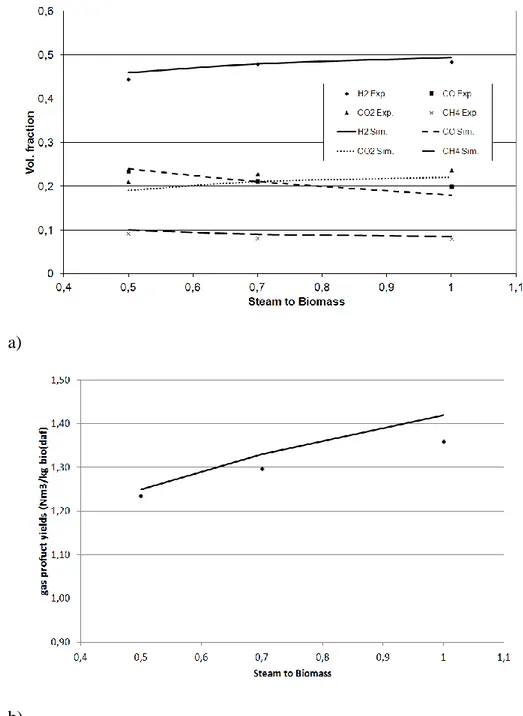
3.5. Simulations and Results ... 54
Chapter 4. Anaerobic Digestion ... 63
4.1. Process details ... 63
4.2. Process stages ... 64
4.2.1. Process kinetics ... 66
4.3. Conditions and variables influencing anaerobic digestion ... 70
4.3.1. Temperature... 71
4.3.2. pH ... 71
4.3.3. C/N ratio ... 72
4.3.4. Retention time ... 72
4.3.5. Organic Loading Rate ... 73
4.3.6. Mixing ... 73 4.4. Bio-Methane Potential (BMP) ... 74 4.4.1. Manometric method ... 75 4.4.2. Volumetric method ... 76 4.5. Laboratory plant ... 77 4.6. Experimental tests ... 79
4.6.1. Co-digestion tests with Olive Mill Solid Waste ... 79
4.6.2. Co-digestion of Poultry Manure and Cheese Whey Wastewater ... 90
4.7. AD Model... 97
4.7.1. AD Simulation Result ... 98
5.1. Introduction ... 101
5.2. Fusion reactions ... 104
5.3. Magnetic and Inertial Confinement ... 108
5.4. ITER and DEMO ... 112
5.4.1. Thermal load issue... 114
5.5. Divertor Tokamak Test ... 116
5.6. Analysis of DTT advanced magnetics configurations ... 117
Conclusions ... 121
1
Abstract (Italiano)
Il proposito della ricerca è stato quello di analizzare la fattibilità e la produttività di impianti di produzione di energia da fonti non tradizionali, come la biomassa, per dare un contributo alla crescente richiesta di energia elettrica mondiale senza far ricorso ai combustibili fossili. Viene presentata quindi una ricerca ad ampio spettro su due possibili processi di conversione della biomassa: termochimici e biochimici. Nel primo caso vengono riportate delle simulazioni effettuate con il software ChemCAD® di un impianto di gassificazione a letto fluido bollente con candele filtranti catalitiche, Water Gas Shift (WGS) e Pressure Swing Adsorption (PSA) realizzato nell’ambito del progetto europeo UNIfHY per la produzione di idrogeno puro. Nel secondo caso vengono presentate delle prove sperimentali di digestione anaerobica a scala di laboratorio, anche nell’ambito del Piano di Sviluppo Rurale (PSR) Misura 124, in cui sono stati utilizzati come biomassa in ingresso scarti provenienti da aziende agricole e allevamenti che rappresentano ad oggi degli inquinanti per i terreni ed i corsi d’acqua, o addirittura delle fonti di perdita monetaria per le aziende. Viene inoltre proposto un modello di digestione anaerobica sviluppato e implementato nel software AQUASIM 2.0 al fine di studiare tramite simulazioni i singoli stadi del processo e l’attività batterica, per poter così verificare a priori la fattibilità e la bontà del processo in funzione del substrato in ingresso. Lo scopo di questo lavoro quindi è quello da un lato di dare una valida alternativa alle aziende che possono trovare negli scarti delle proprie attività una fonte di reddito e, dall’altro, promuovere lo sviluppo e la realizzazione di nuovi impianti di produzione di energia a piccola scala, e contemporaneamente dare una risposta al cambiamento climatico.
Inoltre, nell’ambito di una collaborazione dell’Università della Tuscia e del Centro di Ricerca ENEA Frascati, viene riportato uno studio effettuato su un reattore a fusione termonucleare. Questa tecnologia potrebbe rappresentare una effettiva risposta alla crescente richiesta di energia mondiale tra le fonti di energia alternative che non utilizzano combustibili fossili. In questo lavoro vengono presentate delle simulazioni relative ad un nuovo reattore a fusione termonucleare, DTT, il cui progetto è stato presentato da ENEA nel Luglio 2015. Attraverso tali simulazioni sono state trovate
2 delle possibili risposte alla problematica dei carichi termici presenti su questo tipo di macchina.
3
Abstract (English)
The purpose of this research has been analysing the feasibility and productivity of energy production plants by non-traditional sources as biomass, to contribute to the growing demand of energy without using fossil fuels. A broad-spectrum research on two possible biomass conversion processes is presented: thermochemical and biochemical. In the first case, ChemCAD® software simulation of a bubbling fluidised bed gasifier plant with catalytic filter candles, Water Gas Shift (WGS) and Pressure Swing Adsorption (PSA) are reported; these were realized as part of the European project UNIfHY for pure hydrogen production.
In the second case experimental tests of anaerobic digestion at lab-scale are presented also as part of Rural Development Plan (RDP) project Measure 124. In these tests wastes, from agricultural companies and farms, which are pollutants for soils and watercourses or actually a monetary loss for the companies have been used. Furthermore it is proposed an anaerobic digestion model developed and implemented in the software AQUASIM 2.0 to study via simulations the single stages of the process, the bacterial activity, and to verify a priori the feasibility and the functionality of the process as a function of the input substrate. The purpose of this research is, on one hand providing a valuable alternative to companies, finding in their activity wastes a source of income and, on the other hand promoting the development and the realization of new small-scale energy production plants, thus at the same time to provide a response at the climate change.
Furthermore a study on a thermonuclear fusion reactor, as part of the cooperation between the University of Tuscia and the ENEA Frascati Research Centre, is reported. This technology could represent a valid response at the growing worldwide energy demand among the alternative energy sources that do not use fossil fuels. In this work, simulations of a new thermonuclear fusion reactor, DTT, whose design has been presented by ENEA in July 2015, are introduced. With these simulations a possible solution to the thermal load issue on this kind of machine has been found.
4
Introduction
The energy world consumption has exponentially increased with the industrial, technological and economic development, in different trends in each Country. Nowadays the supply of electricity comes essentially from large power plants, mainly fueled with fossil fuels and nuclear energy. Although these power plants had provided a worldwide efficient service for decades, the demand for energy is growing rapidly due to the rapid social developments in many parts of the world, also because modern economy depends increasingly on the availability of electrical energy. At the same time, modern societies understood that, to fight climate change, it is necessary to reduce the emissions. Moreover an optimum use of traditional energy sources, is required to support the development of energy production from non-traditional sources, such as biomass and thermonuclear fusion.
These issues were the basis of the activities carried out during the three years of the PhD in “Agricultural and forestall system engineering” in Tuscia University, in collaboration with CIRDER (“Centro Interdipartimentale di Ricerca e Diffusione delle
Energie Rinnovabili”) and ENEA Frascati Research Centre.
In the first chapter of this thesis a general introduction on biomass and its physico-chemical characteristics has been done. Furthermore details of the procedure of
5 the laboratory test for its energy characterization according to the European rule have been emphasised.
In the second chapter different biomass conversion processes have been introduced with particular regard to gasification, for the thermochemical processes, and to anaerobic digestion for the biochemical processes.
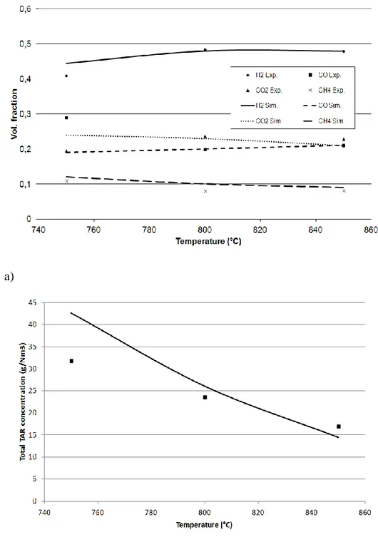
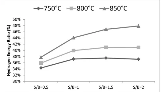
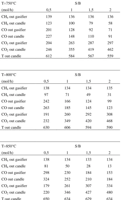
In chapter three biomass gasification process has been investigated, in particular for small size power plants using waste biomass. Waste biomass gasification is an economic process to produce pure hydrogen In particular, small scale applications are very interesting because they follow the low energy density and perishability of this fuel exploiting the biomass directly in loco avoiding therefore disposal costs. At first it has been developed and validated experimentally a model, capable of predicting the performance of a steam blown fluidized bed biomass gasifier during steady state operation. Then simulations activities have been carried out within the European 7FP UNIfHY project. The plant analysed in this research is mainly composed of bubbling fluidized bed gasifier with catalytic filter candles, Water Gas Shift (WGS) and Pressure Swing Absorption (PSA). Focusing on the hydrogen production, a sensitivity study was carried out with ChemCAD® software by varying the steam to biomass ratio and the gasifier operating temperature.
In chapter four anaerobic digestion of waste biomass in co-digestion process has been studied. After biomass energy characterization, experimental tests to evaluate biogas yield from waste biomass have been done with the BATCH mini-digester in a co-digestion process in mesophilic conditions. For the first tests olive mill solid waste (OMSW) has been used in a co-digestion process with cattle manure (CM) and cattle slurry (CS). The other set of tests investigate the biogas production from mixture of Poultry Manure (PM) and Cheese Whey Wastewater (CWW). These tests are part of Rural Development Plan (RDP) project (Reg. 1698/2005 of Lazio 2007/2013), Measure 124: "Cooperation for development of new products, processes and technologies in agriculture, food and forestry: energetic use of agro-industry wastes". Furthermore an anaerobic digestion model has been developed and then implemented in the software AQUASIM 2.0. Anaerobic digestion simulations permit to verify the single process stages and study the bacterial activity, which is difficult to do in experimental tests. In
6 this way it is possible to evaluate the feasibility and the goodness of the anaerobic digestion process as a function of the input substrate.
In Chapter 5 the issue of thermal load in thermonuclear reactor has been investigated, as part of the cooperation between the University of Tuscia and the ENEA Frascati Research Centre. In this work analysis about the electromagnetic aspects that could have an influence on the tokamak divertor were made. In particular simulations on physic divertor of DTT (Divertor Tokamak Test) have been carried out, a project developed by ENEA on July 2015, with the MAXFEA code. The aim of these simulations has been to find am optimal divertor magnetic configuration and to test the performance of plasma when it is used a liquid metal divertor.
Together with the work described above the following articles have been published:
- Steam gasification of pine wood in a fluidized bed reactor: model development and validation at different operative conditions. 21st European Biomass Conference, 2013.
- Parametric experimental tests of steam gasification of pine wood in a fluidized bed reactor. Journal of Agricultural Engineering, 2013.
- State of art of small scale biomass gasification power systems: a review of the different typologies. Energy Procedia, 2014.
- Biomass to fuel cells state of art: A review of the most innovative technology solutions. International Journal of Hydrogen Energy, 2014. - State of art of small scale solar powered ORC systems: A review of the
different typologies and technology perspectives. Energy Procedia, 2014. - Biomass waste shells analysis and advanced gasification tests. Green
Building, Materials and Civil Engineering, 2014.
- Steam gasification of wood biomass in a fluidized biocatalytic system bed gasifier: A model development and validation using experiment and Boubaker Polynomials Expansion Scheme BPES. Int. Journal of Renewable Energy Development (IJRED), 2015.
- Simulations of a Plant with a Fluidized Bed Gasifier WGS and PSA. HIKARI Ltd, 2015.
7 - DEA (Data Envelopment Analysis)-assisted supporting measures for ground coupled heat pumps implementing in Italy: A case study. Energy, 2015.
- Anaerobic co-digestion of olive-mill solid waste with cattle manure and cattle slurry: analysis of bio-methane potential. Energy Procedia, 2015. - Biogas Production from Poultry Manure and Cheese Whey Wastewater
under Mesophilic Conditions in Batch Reactor. Energy Procedia, 2015. - DTT Divertor Tokamak test facility Project Proposal. ENEA, 2015. - Influence of the main gasifier parameters on a real system for hydrogen
production from biomass. International Journal of Hydrogen Energy (under review).
- DTT and advanced magnetic configurations. (To be presented at 22nd
PSI Conference, May 2016)
8
Chapter 1.
Energy characterization of biomass
1.1. Biomass
A first biomass definition is present in Art. 2 of Legislative Decree 387/2003 that reproduces the Directive 2001/77/EC and establishes that “biomass means the biodegradable fraction of products, waste and residues from agriculture (including vegetal and animal substances), forestry and related industries, as well as the biodegradable fraction of industrial and municipal waste”. This definition has been expanded by Legislative Decree 28/2011 implementation of the Directive 2009/28/EC on the promotion of the use of energy from renewable sources and amending and subsequently repealing Directives 2001/77/EC and 2003/30/EC, in which in point e) of Article 2) defines biomass as “…the biodegradable fraction of products, waste and residues from biological origin from agriculture (including vegetal and animal substances), forestry and related industries including fisheries and aquaculture, as well as the biodegradable fraction of industrial and municipal waste”. By these definitions is clear that biomass is a resource available everywhere, clean and renewable. It may be converted in solids, liquids or gaseous fuels, or directly used as fuel. Biomass is composed of water (moisture), dry raw substances and ash. Physico-chemical properties can be established by the composition of the dry substances, highlighting the most suitable energetic conversion. Carbon content higher than nitrogen one indicates the presence of
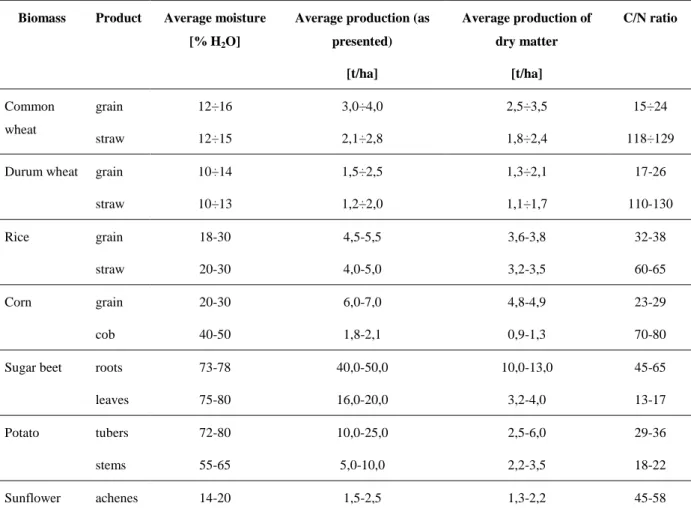
9 organic compounds as lignin, characterized by a complex chemical structure and slow biologic biodegradability. The opposite is for the biomass with low C/N ratio, because it requires substances with high water content and minerals that are an optimum substrate for micro-organisms. In Table 1.1 main biomass usable in Italy to produce energy, the production characteristics, C/N ratio and moisture are shown.
Table 1.1. Average productions and C/N ratio of some Italian culture. Biomass Product Average moisture
[% H2O]
Average production (as presented) [t/ha] Average production of dry matter [t/ha] C/N ratio Common wheat grain straw 12÷16 12÷15 3,0÷4,0 2,1÷2,8 2,5÷3,5 1,8÷2,4 15÷24 118÷129 Durum wheat grain
straw 10÷14 10÷13 1,5÷2,5 1,2÷2,0 1,3÷2,1 1,1÷1,7 17-26 110-130 Rice grain straw 18-30 20-30 4,5-5,5 4,0-5,0 3,6-3,8 3,2-3,5 32-38 60-65 Corn grain cob 20-30 40-50 6,0-7,0 1,8-2,1 4,8-4,9 0,9-1,3 23-29 70-80 Sugar beet roots
leaves 73-78 75-80 40,0-50,0 16,0-20,0 10,0-13,0 3,2-4,0 45-65 13-17 Potato tubers stems 72-80 55-65 10,0-25,0 5,0-10,0 2,5-6,0 2,2-3,5 29-36 18-22 Sunflower achenes 14-20 1,5-2,5 1,3-2,2 45-58
In Table 1.2 chemical composition and Low Heating Value (LHV) of some harvest wood products, culture by-products and wastes are reported. The chemical composition (C, H, O, N, S, Cl) is an important aspect that must be considered [1,2]. For lingo-cellulosic biomass the chemical composition (expressed on a dry and ash free basis) is generally more constant than that of other solid fuels (Municipal Solid Waste, coal). Furthermore, more than 80% of the biomass is volatile and the remaining 20% is charcoal. Coal is typically only 20% volatile, while the remaining 80% is unreactive coke. Generally biomass has very low Sulphur and Chlorine content compared to coal and MSW.
10
Table 1.2. Physico-chemical properties of some biomass.
Material Moisture [%] C [%] H [%] O [%] N [%] S [%] Cl [%] Ashes [%] LHV [MJ/kg] Straw wheat 10-20 43,2 5,00 39,4 0,61 0,11 0,28 11,40 16,49 Straw barley 10-20 39,92 5,27 43,81 1,25 0,10 0,03 9,75 16,24 Straw rice 20-30 41,78 4,63 36,57 0,70 0,08 0,34 15,90 15,34 Cobs Corn 40-50 46,68 5,87 45,46 0,47 0,01 0,21 1,40 17,58 Residual vine pruning 45-55 46,59 5,85 43,90 0,83 0,04 0,08 2,71 17,84
Wood white fir 40-50 49,00 5,98 44,75 0,05 0,01 0,01 0,2 18,74 Wood poplar 40-50 48,45 5,85 43,69 0,47 0,01 0,1 1,43 18,19 Wood oak 40-50 49,98 5,38 43,13 0,35 0,01 0,04 1,61 18,33 Rice husk 10-15 40,96 4,3 35,86 0,40 0,12 0,03 18,35 15,27 Nut shells 10-20 49,98 5,71 43,35 0,21 0,05 0,04 0,71 19,02 Pomace exhausted 10-15 43,73 5,29 37,82 1,5 0,64 0,02 12,52 15,50 Paper 15-20 43,40 5,80 44,30 0,3 0,2 0,4 6,0 18,00
Nowadays, there is a change in the biomass energy uses from traditional and non-commercial, as simple open combustion to produce heat, to a modern one, as advanced processes to produce electricity and bio-fuels integrated in food and biomaterials industries [3]. The technical and economic potentials of biomass are higher than the current world energy consumption [3,4], thus, the challenge is in its viable and sustainable use and not in its availability. Indeed, to really exploit the energy potential of biomass, reliable, high efficiency and low environmental impact, small scale power plants have to be developed, consistent with the low energy density and perishability of this fuel [5–8].
Indeed, one of the major limitations associated with the use of the large bioenergy potential (e.g. the Italian territory amounted to about 30 million metric tons/year [5,9]) is the biomass dispersion. Biomass is the fourth world-wide energy resource (following oil, coal and natural gas) but the energy use of the organic substances is limited by their low energy density, complexity of the supply chain (often in competition with the main uses of organic matter, as food and materials) and high local emissions of pollutants [10].
11 1.2. Energy characterization
For the biomass energy characterization the following analysis must be done:
proximate analysis (moisture, ash and volatile matter content);
ultimate analysis (content of C, H, N, O);
heating value.
All the procedures refer to the international technical rules. In particular the standard techniques of the European Committee of Standardization (CEN) have been followed.
EN 14774-1:2009. Solid biofuels-Determination of moisture content-Oven dry method- Part 1: total moisture-Reference method [11];
EN 14774-2:2009. Solid biofuels-Determination of moisture content-Oven dry method- Part 2: total moisture-Simplified method [12];
EN 14774-3:2009. Solid biofuels-Determination of moisture content-Oven dry method- Part 3: moisture in general analysis sample [13];
EN 14775:2009. Solid biofuel-Determination of Ash content [14];
EN 15148. Solid biofuels–Determination of the content of volatile matter [15];
EN 15104:2011. Solid biofuels-Determination of total content of carbon, hydrogen and nitrogen. Instrumental methods [16];
EN 14918:2009. Solid biofuels-Determination of calorific value [17].
Biomass analysis have been done in the CIRDER laboratory (Orte). Below the details and used equipment are reported.
1.2.1. Proximate analysis
Proximate analysis permits to evaluate moisture content on wet and dry basis, the ash content, and the volatile matter.
1.2.1.1. Total moisture content
Moisture content or water content is the quantity of water in the biomass. To evaluate the percentage of moisture, a representative sample (300 g) is placed in a container of aluminium, and it is dried in an oven at 105±2°C until constant in mass. Constancy in mass is
12 defined as a change not exceeding 0,2% of the total loss in mass during a further period of heating over a period of 60 minutes.
The total moisture content Mar in the biofuel, as received, is calculated with the
equation presents in the regulation [12].
1.2.1.2. Moisture content of the general analysis sample
A fundamental test consists in the determination of the moisture content, Mad, of the
analysis sample [13]. The result of this test is used to evaluate the effective sample moisture. The obtained value is important to correct the heating value, volatile matter content, ash and the ultimate analysis.
The sample is previously finely grind and sieved (1 mm). Each analysis sample (1±0,1 g) must be dried at 105±2°C until constant in mass. It is placed in a crucible with lid and for each sample two tests are necessary. Constancy in mass is defined as a change not exceeding 1 mg in mass during a further period of heating at 105±2°C over a period of 60 minutes. In this way the moisture content of the general analysis sample may be calculated by the formula present in the technical rule.
1.2.1.3. Ash content
Ash content on dry basis represents the mass of residue remaining after the sample is heated under specific conditions, and it is expressed as percentage of mass on dry basis.
The sample is finely grind in a cutting mill and sieved (1 mm). Crucibles must be previously heated in a furnace at 550±10°C for 60 minutes. Then 1±0,1 g of sample is heated in the furnace raising the temperature from 250°C to 550±10°C in accordance with the procedure EN 14775:2009. For each sample two test must be done.
1.2.1.4. Volatile matter content
Volatile matter is determined as the loss in mass, less that due to moisture, when biomass is heated under standardized conditions. The sample (1±0,1 g), finely grind and sieved (1 mm) is heated in a furnace at 900±10°C for 7 minutes.
13 Volatile matters (Vd) on dry basis, expressed as percentage by mass, are calculated by the formula present in the technical rules [15].
1.2.2. Ultimate analysis
Ultimate analysis consists in the determination of the total carbon, hydrogen and nitrogen content in the biomass. The environmental importance of the nitrogen content is linked to emissions of NOx. Hydrogen is important for calculation of the net calorific value.
Carbon content is required for the determination of CO2 emissions.
A sample of 0,150 g, previously finely gring and sieved (1 mm), is used for the test. The oxygen content is measured by empirical relationship (1.1):
𝑂 = 100 − (𝐶 + 𝑁 + 𝐻 + 𝑆) (1.1)
The content of C, H and N are calculated by equations present in the standard EN 15104:2011.
1.2.3. Heating value
The heating value (or calorific value) of a substance, is the amount of heat released during the combustion of a specified amount of it. There are two different heating values: Higher Heating Value (HHV) and Lower Heating Value (LHV). HHV is determined by bringing all the products of combustion back to the original pre-combustion temperature, and in particular condensing any produced vapour. Such measurements often use a standard temperature of 15 °C. LHV is determined by subtracting the heat of vaporization of the water vapour from the HHV. In this study HHV has been determined with an isoperibol calorimeter (Parr 6200) according to EN 14918:2009 (Figure 1.1). In the instrument the shell is at constant temperature (30°C). The bomb, pressurized with excess pure oxygen (40 atm) and containing a weighed mass of a sample (1±0,1 g), is submerged under a known volume of water (2 l) before the charge is electrically ignited. The bomb, with a known mass of sample and oxygen, form a closed system - no gases escape during the reaction. The weighed reactant in the steel container is then ignited. Energy is released by the combustion and heat flow from this crosses the stainless steel wall, thus raising the temperature of the steel bomb, its contents, and the surrounding water jacket. The temperature change in the water is then
14 accurately measured with a thermometer. This reading, along with a bomb factor, is used to calculate the energy given out by the sample burn. A small correction is made to account for the electrical energy input, the burning fuse, and acid production (by titration of the residual liquid). After the rise of temperature is measured, the excess pressure in the bomb is released. The test gives the HHV referred to the sample with relative humidity as that measured for the general analysis sample. Three tests for each sample must be done and the final result is the average of the three obtained values.
15
Chapter 2.
Biomass conversion processes
2.1. Biomass conversion processes
The organic material can be used “directly” by living organisms as their own source of energy and materials (food) or it can be used “indirectly” like a source of external energy (biomass) and materials: (clothing, furniture, buildings chemicals, etc.). Following oil, coal and natural gas, biomass is the fourth most used primary energy resource worldwide. Nevertheless, in industrialized countries it accounts only for about 4% of the share, often being the last remarkable energy resource, after nuclear and hydro, whereas it represents around 35% in the developing countries [4]. This happens because biomass is the most common form of renewable energy and the largest reservoir of solar energy. However, the energy use of the organic substances is limited by their low energy density and complexity of the supply chain, often in competition with the main uses of organic matter as food and materials, and by their high local emissions of pollutants [5]. Thus, as already mentioned, the challenge is in its viable and sustainable use not in the availability. The first element to consider in assessing viable biomass uses is the energy and economic feedstock production costs. The first one is evaluated by Energy Return On Energy Invested, EROEI, that is the
16 ratio of the amount of usable energy delivered from an energy resource to the amount of energy used to obtain that energy resource, while the second one is evaluated by the production cost divided by the useful Heating Value (HV), in €/GJ. The feedstock price is the largest component of the operating costs in a biomass plant and varies from negative price of some waste biomass to high price of some dedicated crops. Fixing an energy yield value of 100 GJ/ha (e.g. yield of 10 t/ha and a calorific value of 10 GJ/t), for a value of 10 GJ/ha for cultivation and harvesting, the energy production cost is 0,1, while a mean economic cost is about €4/GJ. These average optimistic values include, among other items, transport energy and its economic costs of 0,5 MJ/km and 0,02 €/km per ton [3]. Lower yield and lower HV biomass does not have proportionally lower costs; therefore, the energy and economic returns could become negative. For this reason, it is preferable to use low cost residual biomass. The main residual biomass are waste, shells, pruning, straw and agro-industrial residues. Among waste we can mention the Organic Fraction of Municipal Solid Waste (OFMSW) and the manure. Among shells the main used are the shells of pine, hazel, walnuts and almonds. The main pruning are the pruning of beech, oak, spruce, poplar, willow, eucalyptus, grape and olives. The main straw used are the straw of wheat, corn, rye, barley, rice. Among the agro-industrial residues, we can mention food, textile and wood agro-industrial residues like cane trash, exhausted olives, pomace, etc. The second main element to take into consideration is the conversion process that mainly depends on biomass quality and final product desired, as heat, electricity and specific fuel. The efficiency and cost-effectiveness of these processes have a very large range. As in the first element, the energy and economic returns can be easily negative. Indeed, many processes have high-energy requirements and especially the most advanced technologies can have unaffordable investment costs. Strongly related to cost issues are the availability and the full-scale demonstration of advanced conversion technologies, combining high energy conversion efficiency and environmentally sound performance with low investment costs. Last but not least, environmental impacts have to be taken into account. The use of biomass, especially on the large-scale, involves a wide range of environmental implications: soil fertility; leaching of nutrients and biodiversity; deforestation and erosion; landscape, water use; fire and diseases; air, water and ground pollution; etc. In fact, if the “ideal” energy use of biomass produces just the CO2 that the biomass has fixed, there are
pollutant emissions over the whole production-use chain. Differently from other renewable energy sources, biomass, being classifiable as a fuel, and not an energy resource directly convertible like solar, wind, hydro, and geothermal energy, is subjected to all traditional steps
17 needed to make it available on the energy market (production, transport, conversion, distribution, end use). Nevertheless, residual biomass, if used in situ, is subjected only at the last three steps and an accurate analysis and design can change the potential negative impacts into positive ones. Indeed, the use of biomass can also remove soil contaminants and reduce pollution, if the biomass power plants meet strict environmental standards. Finally, social implications have to be carefully taken into account. Bio-energy systems require complex organization, many actors, substantial land areas and have, generally, negative social acceptance. However, biomass is always available and biomass plants can have positive economic, social and environmental impacts, particularly related to the equitable distribution of biomass and the close connection that it establishes between a community and its territory. Summarizing, biomass is a complex energy source that can be processed in many ways leading to a variety of products and by-products, as showed in Figure 2.1.
Figure 2.1. Biomass energy conversion processes.
The primary energy processes of biomass can be divided into three main categories, according to the main energy/ substance used in the process:
1. THERMAL: conversion using thermal energy (combustion; pyrolysis; gasification);
18 2. BIOLOGICAL: conversion using microbial or enzymatic activity (aerobic and
anaerobic digestion, fermentation);
3. MECHANICAL: conversion using mechanical energy (oil extraction).
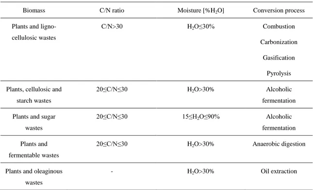
The process choice is mainly determined according to biomass properties and final products required. Biomass properties as moisture, carbon/nitrogen ratio and oil content affect the choice of process category. Thermochemical processes are based on the heat that permits the chemical reactions which transform matter in energy. All the cellulosic and harvested wood products and wastes with a C/N>30 and a moisture <30% are useful. The most suitable biomass for the thermochemical conversions are wood and its derivatives, ligno-cellulosic cultural by-products and some processing wastes. Biochemical processes permit to obtain energy for chemical reaction due to the contribution of enzymes, fungi and micro-organisms, which are formed into the biomass under particular conditions. They are used for biomass with a carbon to nitrogen ratio (C/N) <30 and a moisture >30%. For biochemical conversion aquatic cultures, some cultural by-products, livestock wastes, some processing waste and the biomass of landfills are suitable. In Table 2.1 main biomass with energy conversion processes have been reported.
Table 2.1. Main biomass and conversion processes
Biomass C/N ratio Moisture [%H2O] Conversion process
Plants and ligno-cellulosic wastes
C/N>30 H2O≤30% Combustion
Carbonization Gasification
Pyrolysis Plants, cellulosic and
starch wastes
20≤C/N≤30 H2O>30% Alcoholic
fermentation Plants and sugar
wastes
20≤C/N≤30 15≤H2O≤90% Alcoholic
fermentation Plants and
fermentable wastes
20≤C/N≤30 H2O>30% Anaerobic digestion
Plants and oleaginous wastes
19
Animal wastes 20≤C/N≤30 70≤H2O≤90% Anaerobic digestion
The other properties influence the particular process technologies and the yield and reliability of the entire chain. The final energy vectors required, and in some cases the economic conditions and the environmental standards, influence the process choice. In fact, every process uses all the available chemical energy, but such energy is delivered in a particular way and at different level of efficiency. Aerobic digestion can supply only heat at low temperature thus the process is more useful to treat sewage rather than to produce energy. The direct combustion of solid biomass can supply only heat, which is converted into electricity at low efficiency. I.e. a solid fuel is burned with low efficiency, and, only at large scale, it produces steam suitable for a Steam Turbine (ST). Moreover, the combustion of solid biomass releases many contaminants, especially when air is the limiting reactant. E.g. in tobacco combustion, one of the most studied, until now several thousand products have been identified, many with toxic and carcinogenic action [18]. The other processes transform the chemical energy of biomass into chemical energy of solid (low temperature pyrolysis-carbonisation), liquid (fast pyrolysis, fermentation, oil extraction) and gaseous (gasification, anaerobic digestion) fuels. The fuels so obtained have to be purified and/or upgraded, through subsequent mechanical/physical/chemical or electrical or biological processes. Obviously, a High Calorific Value (HCV) fuel can be easily transported and is amenable to a more efficient use. In fact, producing HCV fuel and/or electricity allows the final energy use to be shifted in space (with fuel also in time) providing a more flexible answer to different energy demands. In fact, with liquid or gas fuels the electricity can be obtained via Combustion Engines (CE), Gas Turbines (GT), Fuel Cells (FC) or Combined Cycles (CC) having better efficiency respect to ST, especially in small scale plants. In brief, the conversion processes that provide an HCV liquid or gas follow the historical fuel trend to more powerful, efficient and clean fuel. The energy end uses are mainly: thermal, mechanical, luminous and electronic. Therefore, the fuels are mainly used to produce heat via combustion, mechanical energy via CE or GT (transport sector), and electricity directly via FC or indirectly via CE, GT, ST, CC and coupled electric generator.
Regarding biogas and syngas, as usual, different anaerobic digestion and gasification processes and different operating conditions give different composition and yield. The operating conditions are mainly temperature and residence time and, for biogas, type of
20 bacteria and acidity value, for syngas, type of oxidant and catalyst/sorbent used. Normally yield is in the range of 0,2-0,7 and 0,5-3 Nm3 of biogas and syngas, respectively, per kg of dry ash free biomass [18]. The impurity concentration (particulate, organic and inorganic trace elements) depends also on the specific type of biomass. Anyway, it is possible to estimate average biogas and syngas composition. Table 2.2 and Table 2.3, show the biogas and syngas dry average compositions.
Table 2.2. Biogas average composition [19–24] Average biogas composition
CH4 (Vol%) CO2 (Vol%) O2-N2 (Vol%) H2S (ppmv) Halogenated hydrocarbons (Vol%) VOC (mg/Nm3) Siloxanes (mg/Nm3) NH3 (ppmv) LHV (MJ/Nm3) 50-80 30-50 0-10 0-4000 1-5 5-300 0-50 100-2000 18-28
Table 2.2 shows that biogas is mainly composed of methane (CH4) and an inert (CO2),
thus different concentration of CH4 gives the different Low Heating Value (LHV). Nitrogen
and Oxygen are present only due to air infiltration owing to anomalous conditions. Therefore, the biogas feeding of the conversion devices fed by methane requires plant modifications to avoid a reduction of power and to guarantee the allowable plant level of the impurities. The impurities are mainly due to presence of sulphur compounds (mainly H2S), halogens
compounds (mainly chlorine compounds), Volatile Organic Compounds (VOC) and siloxanes (O-Si-O compounds).
Table 2.3 shows that syngas is mainly composed of H2, CO, CO2, CH4 and N2 and that
the different concentration of CO, CH4 and H2 gives the different LHV. Nitrogen is present
only if air is used like gasifying agent, or it is due to air infiltration owing to anomalous conditions. The impurities are mainly due to presence of organic compounds (mainly benzene and Topping Atmosphere Residues (TAR) like toluene, naphthalene, etc.), particulate, sulphur compounds (mainly H2S), halogens compounds (mainly HCl) and alkali compounds (like
sodium and potassium compounds). Therefore, the syngas feeding of the conversion devices fed by methane is more difficult not only owing to the lower calorific value and the higher production temperature (700-900 °C of syngas versus 10-55 °C of biogas) but also owing to the presence of different gases from methane and different impurities (mainly TAR).
21
Table 2.3. Syngas average composition [8,20,25–27] Average syngas composition
H2 (Vol%) 10-50 CO (Vol%) 10-45 CO2 (Vol%) 10-30 CH4 (Vol%) 1-20 N2 (Vol%) 0-50 TAR (g/Nm3) 0,01-100 Particulate (g/Nm3) 0-100 H2S (ppmv) 20-200 HCl (ppmv) <500 Alkali (ppmv) ~1 NH3 (ppmv) 100-1000 LHV (MJ/Nm3) 3-20
In the next paragraphs thermochemical and biochemical processes are discussed in detail.
2.2. Thermochemical processes
Thermochemical processes are chemical to thermic energy conversions and vice versa, because they consist in endothermic and exothermic reactions: decompositions chemical reactions. These processes permit to obtain more useful and more exploitable fuels (Figure 2.2). All the thermochemical processes consist in a pre-treatment and then in a conditioning stage. The fuels are used to produce heat by combustion, mechanical energy by Combustion Engine (CE) or Gas Turbine (GT), electric energy by Fuel Cells (FC) or indirectly through mechanical energy (CE, ST, GT, CC) and an electric generator. Each process produces energy vectors (heat, electricity, and fuels with different characteristics) and also sub-products and wastes. Biomass best suited for the thermochemical processes are:
wood and its derivatives;
lingo-cellulosic sub-cultural products;
by-products (shells, stones, etc.);
“dry” urban solids wastes.
22
Figure 2.2. Thermochemical conversion processes
2.2.1. Pyrolysis
Pyrolysis is a thermochemical decomposition process of solid matter, obtained providing heat at low temperature (150-700°C). Between 100°C and 700°C exothermic and endothermic reactions take place, and the macro-molecules are broken in chains with low molecular weight as a function of the pyrolysis methods (Figure 2.3). All the thermochemical processes begin with pyrolysis which is the first stage of combustion and gasification.
Figure 2.3. Scheme of pyrolysis
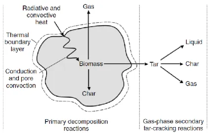
In biomass decomposition complex hydrocarbons molecules are broken down in less complex molecules. The process may takes place both in total absence of oxygen and in presence of little amount of oxygen. In a first stage biomass is converted in solid particulate
23 (CHAR), gas and TAR, which can be broken down in non-condensable gas (as CO, CO2, H2,
CH4), liquid and char (Figure 2.4).
Figure 2.4. Two stages of pyrolysis: primary stage and secondary cracking
Reaction that represents process is (2.1):
𝐶𝑛𝐻𝑚𝑂𝑝(𝐵𝑖𝑜𝑚𝑎𝑠𝑠) → ∑ 𝑙𝑖𝑞𝑢𝑖𝑑 𝐶𝑥𝐻𝑦𝑂𝑧+ ∑ 𝑔𝑎𝑠 𝐶𝑎𝐻𝑏𝑂𝑐 + 𝐻2𝑂 + 𝐶(𝑐ℎ𝑎𝑟) (2.1)
Therefore the products are solids, liquids and gaseous. Solids are in particular char and ash, liquids are heavy hydrocarbons (TAR) and water, and the gases are CO2, CO, H2O, C2H2,
C2H4 and volatile hydrocarbons. The composition and fraction of these products depend on
different conditions as:
biomass composition;
particle size;
heating rate;
operating temperature;
residence time.
Pyrolysis processes are characterized by the temperature rate (slow or fast pyrolysis, as a function of the residence time) and the presence of a medium (hydro-pyrolysis, methane-pyrolysis, etc.), that influence the obtainable products.
There are four different reaction stages:
24 2. Initial stage (100°C-300°C): CO and CO2 are released;
3. Intermediate stage (200°C-600°C): primary pyrolysis; 4. Final stage (300°C-700°C): secondary cracking.
2.2.2. Gasification
Gasification is a thermo-chemical process that converts biomass through partial oxidation into a gaseous mixture of syngas consisting of hydrogen (H2), carbon monoxide
(CO), methane (CH4) and carbon dioxide (CO2) [28]. The oxidant agent can be air, pure O2,
steam, CO2 or their mixtures. The reaction that describes the process is (2.2):
𝐶𝐻𝑎𝑂𝑏+ 𝐻2𝑂 ↔ 𝑥1𝐶 + 𝑥2𝐻2+ 𝑥3𝐶𝑂 + 𝑥4𝐻2𝑂 + 𝑥5𝐶𝑂2+ 𝑥6𝐶𝐻4+ 𝑥7𝐶𝐻𝑥𝑂𝑦 (2.2)
Reactions products are:
syngas;
tar;
char;
ash.
The choice of the oxidant depends on the gas quality desired, plant complexity and the power demand. Gasification process can be applied at biomass that have:
ash content < 5%;
moisture <30%;
absence of melting material at the operating temperature. The process consists mainly in three stages:
drying (about 100°C): vaporization of moisture;
pyrolysis (200-700°C): thermal decomposition of solid in gas, tar and char;
oxidation-reduction processes (700-1000°C): pyrolysis products react with gasification agent generating the final products.
During the process different reactions take place:
pyrolysis of fuel;
heterogeneous reactions:
25
𝐶 + 𝐶𝑂2+ 164.9 𝑘𝐽/𝑚𝑜𝑙 → 2𝐶𝑂 (R2–Boudouard reaction)
𝐶 + 2𝐻2 → 𝐶𝐻4+ 74.9 𝑘𝐽/𝑚𝑜𝑙 (R3–Hydrogasification reaction)
in which the reaction rates are: R1>>R2>>R3
homogeneous reactions:
𝐶𝐻4+ 𝐻2𝑂 + 206 𝑘𝐽/𝑚𝑜𝑙 ↔ 𝐶𝑂 + 3𝐻2 (R4–Methane steam reforming reaction)
𝐶𝑂 + 𝐻2𝑂 ↔ 𝐶𝑂2+ 𝐻2+ 41 𝑘𝐽/𝑚𝑜𝑙 (R5–Water gas shift reaction)
𝐶𝐻𝑥𝑂𝑦+ 𝐻2𝑂 + ∆𝐻 ↔ 𝐶𝑂 + 𝐻2 (R6–Tar steam reforming)
in which the reaction rates are: R5>>R4~R6
Therefore the process is globally endothermic and requires heat to occur.
There are different gasification technologies that can be distinguished as a function of the reactor (fixed or fluidised bed), biomass path, heating (direct or indirect) and operating pressure (atmospheric or pressurised). Within the fixed bed gasifiers it is possible to distinguish updraft (UD) configuration (countercurrent) when biomass move from the top and the gasifying agent from the bottom; downdraft (DD) configuration (concurrent), when the biomass and the gasifying agent move together from the top to the bottom of the reactor; crosscurrent when the biomass moves down and the agent is fed at right angles. Below the main characteristics of fixed bed (from which are derived the moving bed) and fluidised bed gasifier are reported [29].
2.2.2.1. Fixed bed gasifiers
Updraft gasifier
In the UD the downward-moving biomass is dried and pyrolysed, giving char which continues to move down to be gasified, and pyrolysis vapors which are carried upward by the upflowing hot produced gas (Figure 2.5). The TARs in the vapor either condense on the cool descending fuel or are carried out of the reactor with the produced gas, contributing to its low ash but high TAR content (up to 100 g/Nm3). For the extremely high TAR content in the gas, this configuration is more suitable for direct firing, like the small cooking stoves.
26
Figure 2.5. Updraft gasifier configuration
Downdraft gasifier
In the DD the biomass together with the oxidant is forced to pass through a constriction (throat) where most of the gasification reactions occur (Figure 2.6). The reaction products are intimately mixed in the turbulent high-temperature region around the throat (1100-1200°C), which aids TAR cracking. This configuration results in a relatively clean gas from TAR (<10 g/Nm3) even if particulates can be high. The high residence time of biomass leads to a high char conversion (≈95%). Because the gases leave the gasifier unit at temperatures about 900–1000°C, the overall energy efficiency of a downdraft gasifier is low, due to the high heat content carried over by the hot gas. Downdraft is generally utilized for small-scale electricity generation with an internal combustion engine. Downdraft gasifiers are not suitable for scale-up to larger sizes (>1 MW) because they do not allow for uniform distribution of flow and temperature in the constricted area (throat).
27
Figure 2.6. Downdraft gasifier configuration
Crossdraft gasifier
A crossdraft gasifier is a co-current moving-bed reactor, in which the fuel is fed from the top and air is injected through a nozzle from the side (Figure 2.7). One of its important features is a relatively small reaction zone with low thermal capacity, which gives a faster response time than that of any other fixed-moving-bed type. Because its TAR production is low (0,01–0,1 g/Nm3), a crossdraft gasifier requires a relatively simple gas-cleaning system.
28 2.2.2.2. Fluidised bed gasifiers
In fluidised bed gasifiers (FB) the solid fuel, mixed with hot bed material (inert sand, catalyst), are kept in a semi-suspended condition (fluidised state) by means of the gasifying medium through them at the appropriate velocities called minimum fluidization velocity [30]. Unlike the fixed bed gasifier, because the intense gas-solid mixing, the different zones of drying, pyrolysis, oxidation and reduction, cannot be distinguished. Thanks to the excellent gas-solid mixing and to the large thermal inertia of the bed, the temperature and the solid/gas concentration are uniform in the entire bed. For these reasons the biomass conversion in the FB is close to 100% and the throughputs (biomass flow rate per installed reactor area) are double to ten times higher than in the fixed beds (500-1000 kgbiomass/h m2). For the same
reasons, differently to fixed bed gasifiers, which need a fairly specific feedstock, FB are in general more tolerant and suitable for large installations. E.g. FB operate with uniform and relatively low temperatures (700-900°C): most high-ash content fuels, depending on ash chemistry, can be gasified without problems of ash sintering and agglomeration. Finally FB do not require high temperature moving mechanical components (e.g. moving grids like in the moving bed) because the mixing effect is guaranteed in excellent way by the fluidization state. Because of these advantages, most of the current development activities are focused on large-scale FB. However FB still have the following disadvantages. The operation, even if more flexible than fixed bed, is more complicated. The concentration of particulates in the gas is generally higher (from 10 to 100 g/Nm3). The fast movement of the bed material generates high abrasive action. Finally TAR production for fluidised bed gasifier lies between that for updraft (~50 g/Nm3) and downdraft gasifiers (~1 g/Nm3), with an average value of around 10 g/Nm3. The concentration can be reduced to few g/Nm3 adding natural catalyst like olivine as gasifier bed [31].
Bubbling Fluidised Bed gasifier
Bubbling fluidised bed gasifier (BFB) works in minimum fluidisation point (Figure 2.8). The reactor is characterised by the presence of two phases: a fluid and gaseous phase at the bottom composed by heavy particles (fuel, char, ash, etc.) and only a gaseous phase (syngas) at the top (freeboard). In the BFB reactor, the velocity of the ascending gas flow is in the range of 1-3 m/s and the expansion of the solid bed is only in the bottom. Thanks to the low gas velocity, there are not dragging phenomena outside the reactor. High quantity of inert
29 material (sand) is used to stabilize bed and temperature. Into the bed gas bubbles take place, which release giving the idea of the bed boiling. The presence of the bubbles permits a perfect mixing of the solids compounds.
Figure 2.8. Bubbling fluidised bed gasifier
Circulating Fluidised Bed gasifier
CFB works after the minimum fluidisation point and particles circulate in the gas flow (Figure 2.9). A cyclone is used to separate these particles, which then return into the bed. The characteristic velocity of CFB is greater than 4 m/s, and for this bed expansion concerns all the gasifier height and there is not a freeboard zone.
30
Figure 2.9. Circulating fluidised bed gasifier
Dragged Fluidised Bed Gasifier
In dragged fluidised bed gasifier the solid fuel is characterised by a particle size of 50-100 μm, improving intimate contact and so chemical conversion. These reactors work at high temperature (1200-1600°C) to achieve high reaction rates, overcoming ash melting point.
2.2.3. Combustion
Combustion is a high temperature exothermic redox chemical reaction between a fuel and an oxidant, usually oxygen contents in air, that produces a gas mixture.
Solid fuels first undergo endothermic pyrolysis to produce gaseous fuels whose combustion then supplies the heat required to produce more of them. Combustion is often hot enough that a flame is produced. Complete combustion is stoichiometric with respect to the fuel, where there is no remaining fuel, and ideally, no remaining oxidant. Thermodynamically, the chemical equilibrium of combustion in air is overwhelmingly on the side of the products. However, complete combustion is difficult to achieve, since the chemical equilibrium is not necessarily reached, or may contain unburnt products such as carbon monoxide, hydrogen and even carbon (ash). Thus, the produced gas is usually toxic and contains unburned or partially oxidized products. Any combustion at high temperatures in atmospheric air, which is 78% nitrogen, will also create small amounts of several nitrogen
31 oxides, commonly referred to as NOx, since the combustion of nitrogen is thermodynamically favoured at high temperatures. Since combustion is rarely clean, flue gas cleaning or catalytic converters may be required by law.
2.3. Biochemical processes
Biochemical conversion processes mainly include aerobic digestion (fermentation) and anaerobic digestion (Figure 2.10).
They permit to obtain energy by chemical reactions with the contribution of enzymes, fungi and micro-organisms that are generated into the biomass in specific conditions. Aquatic cultures, manure, processes wastes, OFMSW, agriculture and animals sub-products can be converted by these processes.
Figure 2.10. Biochemical conversion processes
2.3.1. Fermentation
Fermentation process permits to obtain ethanol from sugars in cultures and lingo-cellulosic biomass [32]. This process is suitable for all the products and sub-products with high content of glucose, as sugar, cellulose, hemicellulose, lignin and starch. Fermentation is an aerobic process that is characterized by three main steps:
hydrolysis;
32
distillation of products to obtain ethanol. Raw materials for the bioethanol production are:
ad hoc cultivations (corn, sorghum, barley, chard and sugar cane);
wastes of agroforestry cultivations;
agricultural wastes;
municipal solid wastes.
The products of the alcoholic fermentation are ethanol and carbon dioxide. The process is made by unicellular fungi (yeast). These microorganisms play an aerobic digestion in the substrate, using oxygen in the air and transforming sugars in water and carbon dioxide. Then, for lack of oxygen, yeast do fermentation oxidizing sugars in ethylic alcohol and carbon dioxide. The process takes place at ambient temperature (about 18-20°C) during 72-96 hours. Substrate becomes acid with a pH value of about 4 and the alcohol content is at most 12-18%vol. The reaction takes place in a mixed reactor that can work in continuous or in batch.
2.3.2. Anaerobic digestion
Anaerobic digestion is a degradation biologic process of organic matter in anaerobic condition (absence of oxygen) that has as product the biogas. The biogas is a gas mixture mainly composed of methane and carbon dioxide (see Table 2.2). The concentration of these substances in biogas depends by the kind of biomass and the digestion conditions [33]. In the process different bacterial species participate, and each in a specific stage (see Chapter 4). The bacteria can not be selected or modified, but the operating conditions like temperature, flows, mixing and pH can be controlled to promote the growth of the specific bacteria.
The areas of application of this process are three:
1. The treatment of waste water, in particular those with high organic load;
2. The treatment of livestock liquid wastes and biomass, produced for energy purpose or by-products;
3. The recovery of biogas produced by landfill wastes.
Biogas may be utilized in different ways [34]:
direct combustion to produce heat;
33
injection in methane distribution system.
In general the most is the organic content in the substrate, the most is the biogas production. However is very important to control matter quality and in particular to consider:
- composition;
- the presence of essential elements (carbon, nitrogen, phosphorus, sulphur, etc.); - the presence of toxics elements (sodium, potassium, calcium, magnesium,
etc.).
Before being digested, the feedstock has to undergo pre-treatment depending on its characteristics. The purpose of such treatment is to mix different feedstock, to add water or to remove undesirable materials such as large items and inert materials to allow a better digestate quality, a more efficient digestion and it will avoid failure in the process. Digestate can be used as a fertilizer or further processed into compost to increase its quality [35]. The digestion process takes place in a digester, which can be classified in relation to [36]:
Temperature - psycrophilic - mesophylic - termophylic Solids content: - wet (up to 10%) - semi-dry (up to 20%)
- dry (exceeding 20% and up to 40%)
Number of stages in the reactor: - single stages
- separated stages
Operating conditions:
- CSTR (Continuous Stirred Tank Reactor) or PFR (Plug-flow reactor) - BATCH reactor.
34 2.3.2.1. Wet digestion
In wet digestion specific care must be taken for pre-treatments because during the digestion the heavier fraction and contaminants sink and a floating scum layer forms resulting in the formation of three layers in the reactor. The heavier fraction settles at the bottom and may damage the propellers, instead a floating layer accumulates at the top and disrupts mixing. For this, feedstock has to be clean prior to enter in the reactor. Thus the pre-treatments involve the removal of big particles and heavy contaminants. These pre-pre-treatments cause a loss of 15-20% of volatile solids, with corresponding decrease in gas yield. Since total solids content have to be up to 10%, biomass need to be mixed with water [36].
2.3.2.2. Semi-dry digestion
In semi-dry system the solid content is in an intermediate range compared to wet and dry processes (15-20%). Generally a CSTR mixed reactor is used in this digestion, both in mesophilic and termophilic conditions [37]. Also in this case there is formation of three different layers in the reactor, even if the phenomenon is less important. Pre-treatment is important in this system and cause a loss of biodegradable organic matter.
2.3.2.3. Dry digestion
In dry systems the fermenting mass in the digester has a solid content in a range of 20-40%. The pre-treatment step is much simpler than the wet system. Due to the viscosity, plug-flow reactors (PFR) are used. The advantages are that it is technically simple and no mechanical devices need to be installed inside the reactor. Because no mixing occurs in the digester, wastes must be mixed with digestate to provide adequate inoculation. With plug-flow digesters no short-circuiting can happen as there are no moving parts. Feedstock is added at one end, thus pushing the digestate. Reactor is smaller because no water is added, so that the heat required to maintain the temperature in the digester at constant level is less important [35].
35 2.3.2.4. Multi-stages processes
The development of multi-stages anaerobic digestion aimed at improving the process by having separate reactors for the different stages, providing flexibility to optimize each of these reactions. Typically, two reactors are used, the first for hydrolysis/acetogenesis and the second for methanogenesis. In the first reactor, the reaction is limited by the rate of hydrolysys of cellulose; the second by the rate of microbial growth. The two-reactor process permits a certain degree of control of the rate of hydrolysis and methanogenesis. The main advantage of the two-stage system is the greater biological stability. In multi-stages digestion, a distinction must be done between the reactors with and without a biomass retention scheme in the second stage. The aim of biomass retention is to achieve high cell densities of methane-forming. There are two ways to achieve biomass retention. The first one is to rise the solid content in the reactor by coupling the hydraulic and solid retention time. The second one is attached growth, known as fixed film reaction. The microbes are attached to an inert medium such as rock or plastic in the reactor [35].
2.3.2.5. BATCH processes
In BATCH processes digester is filled once with organic matter having high total solid content (30-40% TS). The process works for subsequent stages. There is at first a hydrolytic and acidogenic stage, and then volatile fatty acids are processed in methane.
There are three plant designs:
single stage;
sequential stages;
hybrid BATCH-UASB (Up-flow Anaerobic Sludge Blanket reactor).
In the single-stage plant the leachate is re-circulated at the top of the reactor, which is equivalent to a partial mixing.
The sequential stages system includes two or more reactors. The leachate from the first reactor, containing fresh waste, is re-circulated to the second reactor, containing stabilised waste and vice versa.
In the third type process the leachate produced in the digestion reactor goes to the Up-flow Anaerobic Sludge Blanket (UASB).
36 Batch processes are technically simple, less expensive than other processes and more robust. They work with an organic loading rate of 3-5 kgVS/m3d in mesophilic and thermophilic conditions, with biogas production of about 70 m3/t of waste [36].
37
Chapter 3.
Fluidised Bed Gasification Model and
Simulations
3.1. Gasification process
As said in Chapter 2 biomass gasification is a thermo-chemical conversion process, which utilizes oxidizing agents, to produce a fuel gas rich in hydrogen, carbon monoxide, methane; carbon dioxide, steam and nitrogen, in addition organic (TAR) and inorganic (H2S, HCl, NH3, alkali metals) impurities and particulate are also obtained
[38].
Analysing the small scale gasification power plants, initial attention has been given, to the different biomass feedstock suitable for gasification, focusing particularly on residues with low cost and low environmental impact. Using organic wastes as feedstock in high efficient micro-cogeneration plants would solve all the old-actual drawbacks associated to biomass utilization as energy source. For the selection of the feedstock to be used in gasification processes, the first criterion to be considered is the biomass availability on a significant scale (t/year). In every energy conversion process,
38 because of energy needs in terms of efficiency and power density, fuels with a high LHV are favourites. This means that biomass with lower humidity is preferable. Seasoning can reduce the moisture content or the excess of heat produced by the power plant could be exploited to dry the biomass in order to use also biomass with 50% of moisture. The density affects significantly any freight and storage.
Another important feature that must be considered is the size and shape of the biomass feeding the gasifier. Biomass must be processed to a uniform size or shape to feed into the gasifier at a consistent rate and to ensure homogeneous and efficient gasification. This can lead to significant costs for the shredding: chip size (1-2 cm) is at the moment the right compromise. The chemical composition (C, H, O, N, S, Cl) is another important aspect that must be considered [1,2].
Finally, ash and TAR contents are one of the main obstacles to economical and viable applications of biomass gasification technologies. Fuel with a high ash content require greater attention because ash brings sintering, agglomeration, deposition, erosion and corrosion problems. Furthermore they are elutriated by the produced gas, thus more the ash content is and much more problematic will be the gas cleaning system. TAR condenses at high temperature, causing clogging and damage to the downstream equipment. To sum up, the most suitable biomass for gasification must have availability on significant scale (t/year) and a good physical (low water content and high bulk density) and chemical characteristics (high Caloric Value, high volatile substances, low ash, high Carbon to Nitrogen ratio, low Chlorine and Sulphur content).
As said above (see also Chapter 2) gasification is a process that converts biomass through partial oxidation in syngas. The oxidant is the main parameter affecting the syngas composition, as shown in Table 3.1. Air is the most used gasifying agent, due to the great availability and zero cost, but the large amount of nitrogen not only requires higher power on blowers and bigger equipment, but especially lowers the heating value of the syngas produced. Pure O2, avoiding the nitrogen content, increases
the syngas heating value but also the operating costs due to the O2 production. Steam,
due to the great availability and about zero cost of water, increases the heating value and H2 content of syngas, and can be produced using the excess of heat of the power
plant [39]. Steam or CO2 requires heat supply for the endothermic gasification
39 exchangers, or directly, feeding the gasifier via also air [40] or O2 [41] to partially burn
the biomass. The hot material in fixed bed has to go mechanically from the combustion to the gasification reactor; meanwhile in fluidised bed, the material can circulate via the different pressure/bed height. In any case, the exhaust fumes do not come in contact with the produced gases, which so have high heating value.
Table 3.1. Syngas composition with different oxidant [42,43]
Oxidant Composition (vol%)
H2 CO CO2 CH4 N2 LHV(MJ/Nm3)
Air 9÷10 12÷15 14÷17 2÷4 56÷59 3÷6
Oxygen 30÷34 30÷37 25÷29 4÷6 - 10÷15
Steam/CO2 24÷50 30÷45 10÷19 5÷12 - 12÷20
Conventional small-to-medium scale gasification technologies utilize fixed bed reactors and air as gasification medium. This results in low conversion efficiency and in a syngas with a poor hydrogen fraction, because nitrogen contained in the gasification medium dilutes the syngas and its purification requires higher energy consumption. A possible solution to reduce the amount of N2 in the produced gas is biomass gasification
with oxygen and steam [41]. Nevertheless, cost of oxygen – today especially used in coal gasification [44] – is still too high for a feasible application in small scale plants [31,45–47]. A steam blown indirect heated biomass gasifier, as the one studied in this work, avoids problems caused by air producing a gas with high calorific value (12-14 MJ/Nm3) and high content of hydrogen [31,48], although the plant complexity increases owing to the additional combustor and the additional heat recirculation system between combustor and gasifier.
Gasification is followed by gas cleaning processes as filtration, scrubbing, reforming, cracking, etc. [48–50] (see Paragraph 3.3). Filtration and scrubbing at low temperature are at the moment the most used technologies. They make available a gas at temperature close to ambient. As a consequence the further hydrogen purification steps have low thermal efficiency because additional energy sources or extremely complex heat recovery would be necessary to re-heat syngas for the subsequent gas upgrading by high temperature processes as reforming and cracking [51,52]. Hot gas cleaning and conditioning methods, as the one here analysed, offer several advantages, such as thermal integration with gasification reactor, high TAR conversion and hydrogen rich