Validation of the 1D+2D thermal-‐
hydraulic module of the FRENETIC code
R. Bonifetto, L. Savoldi Richard, R. Zanino, A. Del Nevo
Report RdS/2013/021 Agenzia nazionale per le nuove tecnologie,
VALIDATION OF THE 1D+2D THERMAL-‐HYDRAULIC MODULE OF THE FRENETIC CODE
R. Bonifetto, L. Savoldi Richard, R. Zanino (POLITO), A. Del Nevo (ENEA)
Settembre 2013
Report Ricerca di Sistema Elettrico
Accordo di Programma Ministero dello Sviluppo Economico -‐ ENEA Piano Annuale di Realizzazione 2012
Area: Produzione di energia elettrica e protezione dell'ambiente
Progetto: Sviluppo competenze scientifiche nel campo della sicurezza nucleare e collaborazione ai programmi internazionali per il nucleare di IV Generazione
Obiettivo: Sviluppo competenze scientifiche nel campo della sicurezza nucleare Responsabile del Progetto: Mariano Tarantino, ENEA
Il presente documento descrive le attività di ricerca svolte all’interno dell’Accordo di collaborazione “Sviluppo competenze scientifiche nel campo della sicurezza nucleare e collaborazione ai programmi internazionali per il nucleare di IV generazione” Responsabile scientifico ENEA: Mariano Tarantino
CIRTEN
Consorzio Interuniversitario per la Ricerca TEcnologica Nucleare
Lavoro svolto in esecuzione dell’Attività LP2. A2
AdP MSE-ENEA sulla Ricerca di Sistema Elettrico - Piano Annuale di Realizzazione 2012 Progetto B.3.1 “Sviluppo competenze scientifiche nel campo della sicurezza nucleare e collaborazione ai
programmi internazionali per il nucleare di IV generazione
UNIVERSITY
POLITECNICO DI TORINO
Validation of the 1D+2D thermal-hydraulic module
of the FRENETIC code
Autori
Roberto Bonifetto, Laura Savoldi Richard, Roberto Zanino (PoliTo) Alessandro Del Nevo (ENEA)
CERSE-POLITO RL 1986/2013
Index
Abstract _______________________________________________________ 2
Introduction
___________________________________________________ 3
Scope of the work
_____________________________________________ 3
1
Model description ____________________________________________ 4
1.1
RELAP5-3D model _______________________________________ 7
1.2
FRENETIC model ________________________________________ 8
2
Steady state results ___________________________________________ 9
3
Conclusions ________________________________________________ 12
4
References _________________________________________________ 12
2
Abstract
The FRENETIC code for the dynamic simulation of LFR cores with closed hexagonal fuel elements at a reduced computational cost has been recently developed at Politecnico di Torino by the research group of nuclear engineering. The tool is composed by two modules, the neutronic module and the thermal-hydraulic (TH) module, that can be run together to solve the coupled neutronic and thermal-hydraulic model equations, or separately to analyze only the thermal-hydraulic or neutronic behavior.
The TH module has been successfully validated against experimental data from the CIRCE facility at ENEA Brasimone, as far as the 1D TH analysis along each fuel assembly (FA) is concerned.
The results of a first full core TH benchmark against another computational tools (RELAP5-3D®) are reported here, to check the horizontal 2D coupling model in FRENETIC.
Introduction
The FRENETIC code has been recently developed for the simulation of coupled neutronic/thermal-hydraulic transients in lead-cooled fast reactors (LFR), with the core arranged in closed hexagonal fuel assemblies (FA) [1].
The neutronic module in FRENETIC has evolved from point kinetics [2] to a full 3D time dependent multi-group diffusion solver [3].
The quasi-3D thermal hydraulic (TH) module of FRENETIC solves the 1D (axial) mass momentum and energy conservations laws of the coolant, together with the 1D (axial) heat conduction equation in the fuel pins, in each FA. The FAs are thermally coupled to their neighbors in the other two directions, at selected axial locations.
The TH module of FRENETIC was already successfully validated in the case of a single FA against data from the Lead-Bismuth Eutectic (LBE) CIRCE experiment at ENEA Brasimone [4].
In order to validate the multi-FA capabilities of FRENETIC, and in the absence of easily available thermal-hydraulic data for lead-cooled multi-FA structures, a reasonable alternative is to perform this validation on sodium-cooled geometries relevant to EBR-II [5], see Fig. 1, for which some experimental data are going to be available within the framework of a multi-party benchmarking exercise [6].
Scope of the work
This report will present a qualification of the TH module of the FRENETIC code in a multi-assembly geometry, by means of a benchmark with the RELAP5-3D© code [7].
The final goal is the simulation of two different transients, in a simplified EBR-II geometry, starting from the steady state experimental data of the Shutdown Heat Removal Test (SHRT) #17 [6]:
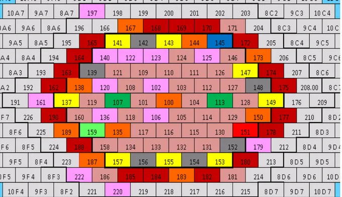
Fig. 1. Sketch of the cross section of the EBR-II core [6]. The red dashed circumference shows the approximate location of the radial boundary of the computational domain.
4 a) complete loss-of-flow,
b) locked rotor in one of the main coolant pumps.
The rationale in the definition of these scenarios is to reproduce transients with significant non-uniformities in the core cross section, in order to test the thermal coupling model between different assemblies. Indeed, the first transient is characterized by quasi symmetric flow at the core inlet and non-uniform power distribution in the core, while the second transient has asymmetric flow and power distribution in the core.
This report contains the results in steady state conditions to assess the inter-assembly thermal coupling strategy adopted in the FRENETIC model.
1 Model description
As the FRENETIC code can only deal with the fuel bundle region of the core (0.61 m axial extension in the EBR-II case), the RELAP5-3D© code [7] is used to provide detailed time-dependent boundary conditions (BC) at the inlet and outlet of each FA in that region. Moreover, the same axially uniform power distribution on the core cross section is provided to both codes. At steady state, the SHRT-17 test data are used, while in transient conditions the RELAP5-3D© code will be used.
For the time being, the radial extension of the FRENETIC model is limited to the 127 central FAs (first 7 rings) of the EBR-II core (region inside the red dashed circle in Fig. 1), i.e. those connected with the high pressure inlet plenum, with adiabatic BC on the side surface of the core. On the other hand, the RELAP-3D© model includes also the thermal coupling with the 42 FAs of the blanket in the next ring, which are connected with the low pressure flow line.
The inlet Na temperature is set to 700 K.
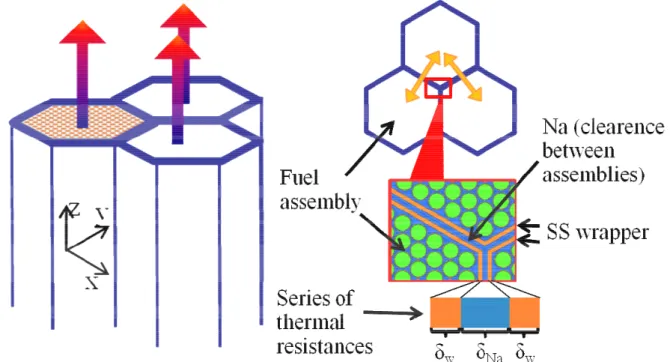
This section contains the description of the two models adopted in the two different codes. The numbering order of the fuel assemblies (FA) in the core is shown in Fig. 2 and Fig. 3.
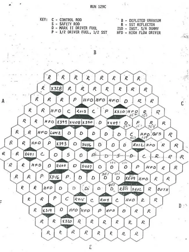
The core load, reported in Fig. 4, corresponds to the load of the Shutdown Heat Removal Test
(SHRT) 17, i.e. the run 129C.
Fig. 3. Zoom of the assemblies numbering order in the present work on the zone of interest (first seven rings).
Fig. 2. Assemblies numbering order in the present work. The central FA (100 in the figure) will be referred to as number 1, and so on.
6
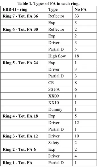
Table 1 reports the types of FA present in the first seven rings.
Table 1. Types of FA in each ring.
EBR-II - ring Type No FA
Ring 7 - Tot. FA 36 Reflector 33
Exp 3
Ring 6 - Tot. FA 30 Reflector 2
Exp 2
Driver 3
Partial D 5 High flow 18
Ring 5 - Tot. FA 24 Exp 1
Driver 3 Partial D 3 CR 8 SS FA 6 XX09 1 XX10 1 Dummy 1
Ring 4 - Tot. FA 18 Exp 5
Driver 12
Partial D 1
Ring 3 - Tot. FA 12 Driver 10
Safety 2
Ring 2 - Tot. FA 6 Exp 2
Driver 4
Ring 1 - Tot. FA Partial D 1
1.1 RELAP5-3D model
The RELAP5-3D model of the EBR-II code is described below. • Core model
o Core modeled with 127 separate channels connected with the high pressure flow line (one by one)
o Blanket modeled with 24 separate channels connected with the low pressure flow line (not relevant for the comparison)
• Pressure at Z-pipe imposed (1.953×10⁵ Pa).
• Pressure at fuel assembly inlet is 6.29×10⁵ Pa in steady state conditions, which is 1.0×10⁵ Pa higher if compared with the estimation provided in the specifications.
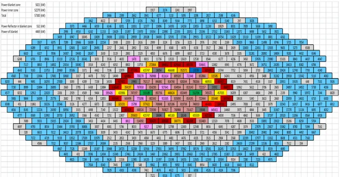
o The pressure drops calculated between the core inlet pressure (in the plena) and the fuel core at wire wrapped fuel bundle outlet is provided, for each channel. • Power imposed (see Fig. 5 and Fig. 6):
o Fuel assembly power based on SHRT-17 benchmark specification
o Uniform axial power distribution. • Mass flow rates @ different FA types. • The coolant inlet temperature is set to 700K.
8
1.2
FRENETIC model
The FRENETIC model of the EBR-II code is described below. • Core model
o Core modeled with 127 separate channels
o Blanket NOT modeled (adiabatic BC prescribed on the outer surface of the 7th ring)
• Power imposed (see Fig. 5 and Fig. 6):
o Same power as Relap5-3D
o Uniform axial power distribution in the active core (0.3429 m from FA inlet).
3533 5340 466688 593705 534641 12482 6945 3450 5713 4330 3678 3105 3007 4081 5786 8033 4542 7251 12807 293603 13361 6438 13084 616643 354197 8015 11736 31281 2883 1529 4850 6676 6899 6837 28147 2630 3119 4776 3672 6052 8802 13753 272864 594852 629163 3314 4243 13533 13619 12530 8544 6177 4236 3031 3536 4693 1470 4478 7352 14049 7752 5004 4462 7196 12979 577745 415747 18054 352572 17270 615305 13744 652866 315585 14241 8216 4956 624863 700270 768988 811614 809320 722348 792117 846881 814768 828244 780266 469555 683927 8119 7431 7238 14155 627921 19965 19392 666915 10962 5612 767650 814290 927641 834934 813143 722157 16209 6307 892756 448624 832449 552704 745572 457035 9464 595426 433906 747197 555189 6873 913305 835890 814195 722444 355440 633560 6354 12855 603645 643499 773098 802343 10618 746910 464681 634516 13495 7008 323231 15798 377422 769848 825186 819738 3975 4844 763827 768988 731427 19048 645411 14460 4498 7140 13122 601829 688324 723590 14030 7536 4842 415747 18694 445183 18140 435339 621326 300771 602498 553469 12520 7078 4608 4434 6465 8812 514092 583670 609380 3453 6045 30536 3009 3455 4242 9217 12969 12788 12683 12348 8656 4356 3541 3099 30402 5470 6673 6775 6696 6735 5711 4287 3374 Fig. 6. Zoom of power distribution in the EBR-II assemblies on the zone of interest (first seven rings).
Power blanket zone 5021 (kW)
Power inner zone 52279 (kW)
Total 57300 (kW)
Power Reflector in blanket zone 552 (kW)
Power of blanket 4469 (kW) 3507 10972 7244 6820 24897 14852 5738 4036 6667 8085 4492 8259 5704 3533 33891 23922 15206 13266 8564 6918 6695 4052 3613 2660 20959 14651 5340 32543 16917 8416 6877 6812 31367 17270 11134 20520 9314 7280 7223 4975 17452 17385 15387 12434 11536 8016 7512 334 4531 7160 13352 8608 4084 4451 4481 4476 17977 466688 6784 593705 534641 12482 6945 3450 37876 23980 15101 5713 4330 3678 3105 1917 3174 3241 1997 3466 2399 2662 3941 4277 5110 7654 6540 7445 6809 32208 32916 2512 2853 3459 3007 4081 5786 8033 4542 7251 12807 293603 13361 6438 13084 616643 354197 5140 297 3028 3073 4466 6059 6146 8201 10351 12377 7963 8249 9164 7771 6898 6153 5095 3298 2817 2598 4146 3862 4622 337 5709 6726 17012 15043 12071 8498 5652 3921 15970 19354 22890 22393 20051 23196 8031 7009 5658 5890 2996 4914 6242 11153 13629 15397 13896 14393 14250 13055 11230 10829 2976 2592 5273 6508 4262 6075 7289 10666 16009 22154 1908 2200 2616 32122 24754 11029 15110 11039 6801 28959 28108 34693 32591 27286 29915 3459 6947 10045 13839 19698 12033 2866 2609 32600 22651 13505 9605 3526 4099 4368 4478 4158 3517 7054 6289 6052 8931 12683 16267 28491 2257 2441 2892 2169 25929 9863 11498 8746 5725 2999 3224 3256 3225 8015 11736 6248 6705 8906 15110 22536 26541 31281 20892 14804 9185 4432 6546 2883 1529 4850 6676 6899 6837 6610 6327 9596 14307 19430 28147 2630 3119 4776 3672 34751 24285 14613 8382 6052 8802 13753 272864 594852 629163 8843 4437 4047 7117 8850 14852 23014 33040 3314 4243 13533 13619 12530 8544 6177 4236 3031 3536 4693 1470 7793 4560 7268 12004 17681 30660 3317 4478 7352 14049 7752 5004 3710 28452 20424 12740 4462 7196 12979 577745 415747 18054 4643 9165 13753 20969 35506 3371 352572 17270 615305 13744 31262 19918 13342 5110 4063 8203 444 9691 18293 27000 652866 315585 14241 8216 4956 3488 624863 700270 768988 811614 809320 722348 792117 846881 814768 828244 780266 469555 683927 8119 7431 4518 3107 20931 19105 648 7101 5926 3093 4289 7238 14155 627921 19965 4577 8232 12912 22020 2206 2929 19392 666915 10962 5612 3706 2665 767650 814290 927641 834934 813143 722157 7230 8999 15894 26895 2660 3795 16209 6307 4404 2989 2139 9940 892756 448624 832449 552704 745572 457035 4569 9464 595426 433906 747197 555189 6710 6300 8308 451 11861 18226 33546 3126 4277 6873 913305 835890 814195 722444 355440 633560 6354 12855 603645 643499 773098 802343 5906 9844 16009 25776 2682 3790 10618 4656 8145 12224 24390 30956 3315 3079 746910 464681 634516 13495 7008 4392 323231 15798 377422 769848 825186 819738 3975 4844 3445 763827 768988 731427 19048 645411 14460 4498 7140 13122 601829 688324 723590 14030 7536 4842 3636 37197 415747 18694 445183 18140 435339 621326 4777 8369 13992 20730 26952 3366 300771 602498 553469 12520 7078 4608 4434 6465 8812 514092 583670 609380 7689 9333 15015 23024 33824 3453 6045 328 6633 9112 14613 20778 30536 3009 3455 4242 9217 12969 12788 12683 12348 8656 4697 4793 8054 15464 19765 36806 7572 4729 9159 13552 17509 31979 4356 3541 3099 30402 20481 14642 5470 6673 6775 6696 6735 5711 10848 24725 3281 2969 2612 2182 24639 17299 2135 2568 2968 3229 3389 3437 4586 7312 9037 11584 17557 24304 4815 7204 5491 9624 11536 11985 14135 17461 24104 1460 23062 19851 20663 13763 14422 10398 8319 4601 431 9596 12434 15349 27831 34091 37962 30574 32581 26245 4667 7528 11249 15187 7829 4303 4598 7461 4676 4622 548 9062 8055 9092 8345 8954 15397 15598 14355 13505 11593 4240 4287 3374 27879 23827 15062 8780 5394 7161 5815 6058 4526 4324 7596 7121 6516 6775 307 8420 6618 6643 4512 10504 6439 422 4602 4690 4105 3515 2904 2568 32199
• BC (from Relap5-3D)
o Mass flow rates each FA inlet.
o Pressure at each FA outlet (pressure at the core bundle outlet).
o Coolant inlet temperature (set to 700 K). • Additional BC: all the pins are adiabatic at their ends.
• Friction factor from [8] Chapter 9, "Single-Phase Fluid Mechanics", VI - Pressure drop in rod bundles, for bare rod bundles.
• Heat transfer coefficient: Mikityuk correlation [9] (for FA without pins Dittus-Boelter [10] is used). Schad correlation [8] is also used.
Neighboring FAs are thermally coupled in FRENETIC through a nominal 1D thermal resistance – series of the two stainless steel hexagonal wrappers (each 1.016 mm thick) and of the Na, assumed stagnant, in the clearance (0.764 mm thick) between FAs (see Fig. 7).
2 Steady state results
The comparison between the FRENETIC and RELAP-3D© preliminary results at steady state is presented in this Section.
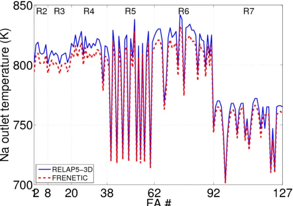
In a first test, the FAs are assumed to be adiabatic (decoupled). The results of the two codes, shown in Fig. 8, are qualitatively in good agreement, while the FRENETIC outlet temperature is almost everywhere ~10 K lower than RELAP5-3D© results. We discovered that this is due to a difference in the Na properties implemented in the two codes (taken from [11] in FRENETIC, from [12] in RELAP5-3D©), and in particular to a discrepancy of ~10% in the specific heat at constant pressure (see Fig. 9). In the future this discrepancy will be eliminated by adopting in both codes a consistent set of properties.
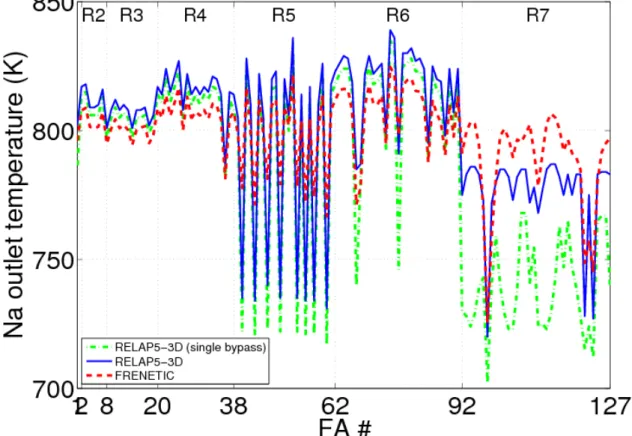
10 We also considered a more realistic and interesting second test (see Fig. 10), where the FAs are thermally coupled to each other. Of course, in such a comparison the outermost (7th) ring is
Fig. 9. Comparison between Na specific heat at constant pressure implemented in the two codes. Fig. 8. Comparison between computed steady state Na temperatures at the outlet of the fuel bundle region, in each adiabatic FA. The number R* of the corresponding ring is reported at the top of the figure.
somehow anomalous, due to the above-mentioned different BC applied in the two codes (FRENETIC outlet temperatures are obviously going to be much higher than RELAP5-3D© ones, as the FAs in that ring are heated by the 6th ring FAs, but not cooled by the 8th ring ones, as in the RELAP5-3D© case).
However, it also turned out that our first model in RELAP5-3D© of the Na bypass flow in the clearances between the FAs was too rough: indeed, this flow was modeled so far in RELAP5-3D© with a single channel, collecting the flow from the clearances in the entire core, most of which is not heated. This results in a very low temperature increase of the bypass, so that in the in RELAP5-3D© model the coolant flowing in the clearances of the FAs in the central part of the core (the hottest, and the only one analyzed here) is cooling the FAs. On the contrary, the simplified thermal coupling model between FAs adopted by the FRENETIC code tends to smooth the temperature difference between neighboring FAs, leading to a temperature increase of the colder FAs.
A more detailed RELAP5-3D® model of the bypass flow has then been developed, where the bypass flow is divided into two bypass channels: one for the 127 central assemblies included in the FRENETIC model and another one for all the other assemblies. The results of the comparison at steady state are also reported in Fig. 10, showing that the coolant outlet temperature is indeed higher with respect to the one computed with a single bypass channel. The effect of the different BC applied at the interface between the 7th and the 8th rings is still evident, as the RELAP5-3D® temperature is again lower than the FRENETIC one due to the cooling effect of the reflector (cold) assemblies in the 8th ring.
Fig. 10. Comparison between computed steady state Na temperatures at the outlet of the fuel bundle region, in each FA. The number R* of the corresponding ring is reported at the top of the figure. For the RELAP5-3D® results, both the cases with single (dash-dotted green) and double (solid blue) bypass model
12
3 Conclusions
An encouraging agreement between FRENETIC and RELAP-3D© results at steady state has been shown above [13]. This first test has also highlighted some issues, concerning the Na properties and the model of the Na in the clearances between FAs, which are being taken care of. After the successful completion of this benchmark, it should become meaningful to apply FRENETIC to the analysis of the actual SHRTs in EBR-II.
4 References
1. R Bonifetto, S Dulla, P Ravetto, L Savoldi Richard, R Zanino, “A full-core coupled neutronic/thermal-hydraulic code for the modeling of lead-cooled nuclear fast reactors”,
Nuclear Engineering and Design, n. 261 (2013), 85-94.
2. R. Bonifetto, S. Dulla, P. Ravetto, L. Savoldi Richard, R. Zanino, “Progress in multi-physics modeling of innovative lead-cooled fast reactors”, Fusion Science and Technology, n. 61 (2012), 293-297.
3. R. Bonifetto, D. Caron, S. Dulla, P. Ravetto, L. Savoldi Richard, R. Zanino, “Extension of the FRENETIC code capabilities to the three-dimensional coupled dynamic simulation of LFR,” presented at the 16th International Conference on Emerging Nuclear Energy Systems (ICENES), May 26-30, 2013.
4. R. Zanino, R. Bonifetto, A. Ciampichetti, I. Di Piazza, L. Savoldi Richard and M. Tarantino, “First Validation of the FRENETIC Code Thermal-Hydraulic Model against the ENEA Integral Circulation Experiment,” Transactions of the American Nuclear Society, n. 107 (2012), 1395-1398.
5. G. H. Golden, et al., “Evolution of thermal-hydraulics testing in EBR-II,” Nuclear
Engineering and Design, n. 101 (1987), 3-12.
6. T. Sumner, T.Y.C. Wei, “Benchmark Specifications and Data Requirements for EBR II Shutdown Heat Removal Tests SHRT 17 and SHRT 45R”, Nuclear Engineering Division Argonne National Laboratory, ANL-ARC-226-(Rev 1), May 31, 2012.
7. The RELAP5-3D© Code Development Team, “RELAP5-3D© Code Manual Volume II: User’s Guide and Input Requirements,” INEEL-EXT-98-00834 Rev. 4.0 June 2012.
8. N. E. Todreas, M. S. Kazimi, “Nuclear Systems”, vol. 1, Hemisphere, New York (1993). 9. K. Mikityuk, "Heat transfer to liquid metal: Review of data and correlations for tube
bundles", Nuclear Engineering and Design, n. 239 (2009), 680-687.
10. F. P. Incropera, D. Dewitt, “Fundamentals of heat and mass transfer”, Wiley & Sons, 2006 (sixth edition).
11. J. K. FINK, L. LEIBOWITZ, “Thermodynamic and Transport Properties of Sodium Liquid and Vapor”, Reactor Engineering Division Argonne National Laboratory, ANL/RE-95/2, January 1995.
12. R. A. Riemke, C. B. Davis, R. R. Schultz, "RELAP5-3D Code Includes Athena Features and Models", International Conference on Nuclear Engineering – ICONE 14-89217, July 2006. 13. R. Zanino, R. Bonifetto, A. Del Nevo, E. Martelli, L. Savoldi Richard, “Thermal-Hydraulic
Code-to-Code Benchmark in a Simplified EBR-II Geometry”, to appear in Transactions of
5 Breve CV del gruppo di lavoro
Il gruppo di lavoro impegnato nell'attività opera presso il Dipartimento Energia del Politecnico di Torino ed è costituito da un professore ordinario (Roberto Zanino, impianti nucleari), un ricercatore confermato (Laura Savoldi, impianti nucleari), e da un dottorando (Roberto Bonifetto) iscritto al III anno di Dottorato in Energetica.
Il gruppo ha una lunga esperienza nella ricerca nel campo dell’ingegneria nucleare, sia nel settore della fusione, che, più recentemente, nel settore della fissione.
Nel settore della fissione l’attività riguarda lo sviluppo di strumenti per il calcolo accoppiato (neutronico e termo-idraulico) della dinamica dei reattori, in particolare per applicazioni ai sistemi nucleari avanzati (reattori innovativi di IV generazione). Nel settore della fusione il gruppo si è occupato dell’analisi termofluidodinamica di componenti di reattori a confinamento magnetico e in particolare dello sviluppo di codici per la modellazione del sistema dei magneti superconduttori e dell’applicazione di software CFD per l’analisi di blanket, first wall e vacuum vessel.
L’attività di Roberto Bonifetto comprende lo sviluppo e l’applicazione di codici per la modellazione di reattori nucleari a fissione (il codice presentato in questo lavoro) e a fusione (il codice 4C per l’analisi termofluidodinamica dei magneti superconduttori).
Nel lavoro presentato in questo rapporto sono state utilizzate le metodologie di simulazione termoidraulica messe a punto nel settore della fusione per lo sviluppo di un modulo di codice di multifisica per l’analisi dinamica di un reattore veloce.
Maggiori dettagli e l'elenco delle pubblicazioni più recenti dei membri del gruppo si possono trovare sul sito Web del Politecnico di Torino:
http://porto.polito.it/view/creators/Zanino=3ARoberto=3A001876=3A.html http://porto.polito.it/view/creators/Savoldi=3ALaura=3A003575=3A.html http://porto.polito.it/view/creators/Bonifetto=3ARoberto=3A026979=3A.html
![Fig. 1. Sketch of the cross section of the EBR-II core [6]. The red dashed circumference shows the approximate location of the radial boundary of the computational domain](https://thumb-eu.123doks.com/thumbv2/123dokorg/5614662.68300/7.892.242.650.416.764/sketch-section-circumference-approximate-location-boundary-computational-domain.webp)