POLITECNICO DI TORINO
Dipartimento di Architettura e Design
Corso di Laurea Magistrale in Architettura per il Progetto Sostenibile
Tesi di Laurea
“Precast concrete panels for the Chinese market: the application of the
Performance-Based Building Design approach to define a database of
technological solutions”
Student: Andrea Alfredo Merola
Italian supervisors: Prof. Lorenzo Savio, Prof.ssa Tedesco Silvia
This Thesis is dedicated to my friend Alessandra Pelizzi
Acknowledgments
This thesis would not have been possible without the support and encouragement from
many people. The greatest thanks go to my Italian supervisors Prof. Lorenzo Savio, Prof. Silvia Tedesco for having given me the opportunity to take part in this bilateral project and having supervise and inspired me during the entire experience. Another special thanks are dedicated to my Chinese supervisor Prof. Sun Feifei for his indispensable motivation and help during my stay in Shanghai. Thanks to him I had the chance to get in touch with an astonishing new culture and to broaden my technical and human knowledge. I am sincerely grateful for his dedication to try to give me the opportunity of an internship in Shanghai, despite the Chinese government’s restrictions.
I would like to thank the Italian General Consulate in Shanghai and especially Prof. Roberto Pagani to having invited me in numerous exchanging events and provided me an office room in Yunchou Building, inside the Tongji University Campus.
I would like to acknowledge my friends Caterina and Giada for your linguist supervision and Paola, Andrea, Francesco, Mattia, Luca and Dario for having made the time I spent writing this Thesis much more enjoyable.
Many thanks for the support that my family provided me. To my parents Mansueta and Ric-cardo, my sister Roberta thank you for your love, understanding and motivation during this experience.
INDEX
PREFACE...5
• Part I – State-of-the-art
1. CURRENT KNOWLEDGE IN BUILDING PREFABRICATION...10
1.1 Prefabricated cladding systems...10
1.2 Precast concrete panels...28
2. PERFORMANCE-BASED BUILDING DESIGN (PBD) APPROACH
TOWARDS TECNHOLOGICAL SOLUTIONS...56
• Part II – The context
3. CHINESE REAL ESTATE MARKET AND THE USE OF CLADDING
SYSTEMS
...674. CHINESE STAKEHOLDERS’ NEEDS
...704.1 The needs analysed...70
4.2 Users...71
4.3 Entrepreneur/owner...78
4.4 Design team...81
4.5 Manufacturer...82
4.6 Public administration...84
4.7 Stakeholders’ needs comparisons and final considerations...86
5. PRECAST CONCRETE PANELS PERFORMANCE REQUIREMENTS...90
5.1 The performance requirements analysed...90
5.2 Thermal strategies and parameters...91
5.3 Acoustic performance...99
5.4 Moisture safety...102
5.5 IAQ Indoor Air Quality...104
5.8 Surface aesthetics...108
5.9 Energy production from renewable energy sources...110
5.10 Communication...113
5.11 Durability...114
• Part III – The tool
6. PANdwich: THE DATABASE FOR PRECAST PANELS
TECHNICAL SOLUTIONS...120
6.1 Who it is for...120 6.2 What it is for...120 6.3 How it works...121 6.4 Input data...123 6.5 Rating system...123 6.6 Output data...124 6.7 Graphical interface...125 6.8 An example of application...1257. CONCLUSIONS...168
PREFACE
Abstract
Nowadays the sector of prefabricated constructions is subjected to continuous progress and it is moving towards high quality design solutions, all developed following more sustainable approaches. At the base of this method there is the conviction that the construction must be born entirely in the factory. Once out of the plant, prefab components are already completed with finishes, windows and they require only operations of assembly and sealing. It represents one of the most employed buildings’ technologies and every year it creates an enormous amount of incomes and employments worldwide. By now, thousands of hou-sing, public and industrial buildings have been built with this method, especially in Asia, North America, Oceania and United Kingdom.
Within the wide range of prefabricated components, prefab claddings and in particular precast concrete panels are playing a stunning role as innovative solu-tion of building’s envelope. There are many researches which have been carried out over the years to transform the prefabricated envelope into an ingenious and satisfactory interface. Compared to on-site claddings, emerge some indispu-table advantages such as flexibility, long-term life cycle, strict controls of ma-nufacturing quality, vast possibility of aesthetic customisation, low production and assembly costs. Precast concrete claddings are especially appreciated in high-rising constructions thanks to the speed of all constructing operations and contained employment of workforce. Considering an international prospecti-ve, China has demonstrated outstanding expertise in the use of this cladding technology triggered by the swift in urban development which has taken place since 1980s. However, despite the remarkable expansion, China is facing with the harsh environmental pollution and resources exploitation added to inherent issues such as seismic activities and demographic increase. In order to tackle these problems, the reply from the construction sector is to strive for elaborating
more advanced technologies which in cladding field deal with the enhance of traditional precast concrete claddings’ performances. In this regard, this Thesis aims to take stock of the contemporary applications of precast concrete cladding and, following performance-based building design (PBD) approach, propose a database for precast panels technical solutions. The PBD method has been selected as an indispensable guide for the elaboration of Thesis’ different steps. Thanks to the principles of this method, it has been possible to follow precise stages, from the collection of the stakeholders’ needs to the definition of the related performance requirements, which have brought to the design of PAN-dwich, the database for precast panels technical solutions. It stands as a practical tool proposed to lead the professionals towards the most suitable technical solu-tions which can fit their projects, optimising also their workflow and inspiration.
Aims and motivations
The Thesis’ main goal is to design the database for precast panels technical solutions called PANdwich. It has been thought to be an intuitive and user-frien-dly tool able to support the professionals in the selection of the most suitable technical solution in the broad and complex world of precast panels. This final project has been the result of the analytical process carried out by the coopera-tion between two research groups: the first one is composed by the Tongji Uni-versity’s structural engineering students, headed by professor Sun Feifei, and the second one is composed by the Politecnico di Torino’s architecture student, headed by professors Lorenzo Savio and Silvia Tedesco. It is also important to mention the Sino-Italian Workshop “SHANGHAI 2035 – striving for the excel-lent global city”, carried out under the aegis of Tongji University, Politecnico di Torino, Italian Ministry of Environment, Italian General Consulate in Shanghai and China Center, whose meetings and contents have stimulate the development of this work.
As a student of Master’s Degree in Architecture for the Sustainability Design, I seized the opportunity of this Thesis to get in touch with a new culture from all points of views. During the time I spent in Shanghai cooperating with professor Sun and his students, I realized the complexity of Chines building requirements and frameworks, quite different from Italians ones. Indeed, China is living a central historical changing in terms of energy supply in every field: its stagge-ring economical growth is about to pass from the dependence of fossil fuels to a larger exploitation of renewable resources. This is ascertained by enormous investments in more sustainable approaches that involve also the construction sector. Hence, it is the most harmful field together with industry and transports. Given that precast concrete structures are the most applied construction techno-logies to build Chinese cities, I capture the opportunity to work on how to turn this solidify practises into a more efficient systems considering both
architectu-Methodological framework
PERFORMANCE-BASED BUILDING
DESIGN APPROACH (PBD)
PREFABRICATED CLADDING SYSTEMS
CHINESE REAL ESTATE MARkET
PRECAST CONCRETE PANELS
Par t I – St ate-of-the-ar t Par t II – the context STEP I STEP III STEP V STEP VI STEP IV STEP II
CHINESE STAkEHOLDERS NEEDS
PRECAST PANELS PERFORMANCE
REQUIREMENTS
The the main aspects of the principal
con-text in which the the-sis is developed
The study of the key
topic, analysed from
architectural and engi-neering prospective
The breakdown and analysis of stakehol-ders’ needs to run the
project The introduction of
the general topic,
analysed from archi-tectural and enginee-ring point of view
The outline of the key
methodology
embra-cing all the project’s steps
The breakdown and analysis of perfor-mances requirements
1. CURRENT KNOWLEDGE IN BUILDING
PREFABRICATION
1.1 Prefabricated cladding systems
Prefabrication is defined as «the practise of assembling components of a structure in a factory or in another manufacturing site and transporting complete assemblies or sub-assemblies to the construction site where the structure is located» (Campioli & Lavagna, 2013).
As stated in the definition, the key concept of prefabrication consists in the place where con-struction elements are produced and the way in which they are realised. The merit of having introduced changes in the production and construction processes of buildings is attributed to industrialization. Nowadays, this has allowed to move many processes, which were previously carried out on the construction site, inside the industrial plants. Once built, the components are transported to the site as ready-made parts to be assembled. However, it still exists the oppor-tunity to employ one of two mentioned methods of construction: on-site or using prefabricated components. An example can be load-bearing structures made by reinforced concrete. There are also cases where the entire building is prefabricated, that is, where all the parts that make up it were made in the factory and simply assembled on site. While the on-site construction allows dimensional adjustments and it does not force the designers to be very attentive to dimensional control, the use of prefabricated components require that the designers crucially consider the accuracy of whole elements’ dimensions and the relationships among the parts. This means that, in the case of prefab systems, the tolerance between the designed elements and the con-structed ones is in the order of the millimeter, significantly lower than on-site technique. Often the size of the prefabricated components depends on the production supply; at the same time, the current flexibility of the production processes also allows special productions. Indeed, it
PREFABRICATION window slab cladding panels foundation beams columns loadbearing panels stairway
continuously adjusted to meet the design desired. The same goes for insulating material panels which are cut according to the surface of the envelope needed to be covered. These practices create also extensive waste which can be disposed only in the landfill.
Nowadays, on-site and prefabricated methods coexist and are associated with the different com-ponents of the building: typically, the load-bearing structures are made on the construction site while the envelope, windows, columns, beams, foundations, cladding panels, slab, stairway are prefabricated elements simply assembled. Finally, the choice between the two depends on the complexity of the project: generally, the prefabrication is favored for big scale buildings.
The brief history of prefabricated buildings
The first more renowned example of a partially prefabricated building is Paxton’s Crystal Pa-lace, erected in London in 1851 to house the Universal Exposition. The cutting-edge building was born by a steal structure characterised by compact sections elements, all fabricated with industrialised methods. However, the success of this new technology happened within the end of the IXX century and the First World War. The gory conflict carried out the necessity of constructing numerous temporary and emergency buildings in a short time, minimising the costs. Between the two World Wars, the construction sector made important experiments on
came the Second World War, prefabrication was more broadly used in civil applications such as housing and educational buildings. The purpose was always to reduce the costs and time, basic needs requested in the reconstruction period after the 1945. Moreover, in this period were taken the first steps toward the standardisation of prefab systems in order to make the realisations safer and homologated. Some illustrious architects, such as Le Corbusier, were fascinated by this technology and wanted to experiment it in their design. The 1970s was a decade where two issues emerged: the first one was the consequence of the oil crisis which obliged to find new materials and industrialized techniques to make building more efficient from an energetic prospective. The second issue was the acknowledgment that the post-war prefabricated buildings were built often at the expense of quality, causing untimely deteriora-tion and loss of minimal watertight and fire resistance requirements. This brought about huge critics on this building typology which affected its popularity worldwide. The successive two decades, 1980s and 1990s, saw a substantial recovery of industrialized architecture thanks to the renovated orientation towards innovative materials, customised design solutions and new production processes. Everything was put in place to assure a better comprehensive quality of prefab components; this always flanked the main advantages of serial constructions whi-ch are low costs and reduced time. In the early 2000s, the incessant researwhi-ch led to the ask of new requirements related to the reduction of environmental impacts and the sustainable development in buildings. The initials higher costs due to the employment of new efficient features was quickly compensated by the big benefits in terms of versatility and efficient.
Cladding functions
rability, sustainability, energy efficiency, and improve occupant comfort and safety. Thus, its relevance is fundamental also in terms of interior ambiences and occupants’ comfort. Following the same logic and definitions proposed by Andrew C. Baird in “Seismic per-formance of precast concrete, cladding systems”(Baird, 2014), the functions of the clad-ding panels could be divided into two categories: primary and secondary. The primary fun-ctions consist in the fundamental architectural requirements that the panels should fulfil:
• «Define the aesthetic image of the building; • Keep water out of the building;
• Prevent air leakage;
• Control the passage of light and heat (radiation and conduction); • Control sound from the outside;
• Avoid thermal bridges.»
The secondary functions are referred to derived aspects which count:
• «Adjust to movement in the building due to wind, earthquakes, creep, etc. • Adjust to thermal expansions and contractions;
• Control the passage of water vapour; • Resist fire;
• Resist weather conditions gracefully (without streaking, oxidation, corrosion, freeze-thaw spalling).»
As stated by Andrew C. Baird in the same Thesis, the present innovations on cladding pa-nels are oriented towards an enhancement of primary functions, especially the contents whi-ch involve energy efficiency and occupant’s comfort. These indoor and outdoor concepts are strictly related to the performances displayed by the building’s envelope and, in particular, by its materials employed, the thicknesses designed, and the insulation devices supplied. These qualities are more and more often assessed by multicriteria rating systems which cer-tificate the degree of sustainability taking into account numerous building’s parameters. The
purpose is to sensitise designers and constructors to improve the environmental quality of ildings and components in order to develop the so called “green building” or “low energy bu-ildings”. The assessment protocols can be provided at national level, such as the “Protocollo Itaca Nazionale 2011” for Italy, or at international level, such as LEED (Leadership in Energy and Environmental Design) delivered by USGBC (U.S. Green Building Council) and BRE-EM (Building Research Establishment Environmental Assessment Method) delivered by BRE.
Cladding classification
Due to the huge variety of cladding systems currently available on the market, it important to classify the most relevant typologies to make the further considerations clearer. Different types are applied for different uses buildings: from residential as well as retail, to industrial as well as services. Moreover, the envelope systems are designed to consider the performances required in a specific area, such as earthquakes’ protection or extra insulation due to the harsh weather. Sometimes it happens that in the same building are employed different typologies of cladding in order to meet different needs. Despite this large array, it follows a brief list proposed by Andrew C. Baird (Baird, 2014), with further considerations of Precast Concrete Institute (PCI, 2007).
• Curtain wall Stick curtain Unitised system
• Lightweight panels • Heavy panels
• Curtain wall
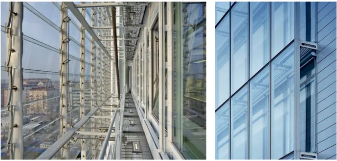
The curtain wall cladding has been adopted since 1960s and it is applicable for buildings characterised by columns and beams structure. It is defined as “curtain wall” because the envelope covers continuously the loadbearing frame, without interruptions in correspon-dence of slabs and pillars (Campioli & Lavagna, 2013). They are designed to span multiple floors. Generally, the width of the window part is ampler than the wall one. Curtain wall pa-nels are not loadbearing elements, they are composed by repeated prefabricated units, they are reversible and they are assembled thanks to bolts and sealants. Curtain wall panels are the most generic definition of lightweight cladding systems which include four sub-typolo-gies: stick built system, unitised system, structural glazing, frameless glazing.
Stick curtain
The stick curtain system is composed by aluminium frame consisting of continuous per-pendicular transoms and mullions characterised by a hollow section. This structure en-compasses pieces of glass or thin opaque panels. It is bolted to the building frame in cor-respondence of slabs. Mullions have generally a length of 50 mm and a profundity which depends on the span between two slabs (Campioli & Lavagna, 2013). The final image of the façade seems to be made predominantly by glass.
Unitised system
The unitised systems are constituted by prefab modular elements with a hei-ght which covers the span between two slabs. The frame of transoms and mul-lions, the glass and the opaque parts are put together in the plant as a single panel and then, once reached the construction site, it is just lifted in the required position.
Structural glazing
The first step to obtain the structural glazing is to seal the perimeter of the glass pane to a primary aluminium or steal frame. Secondly, it is connected to the transom and mullion
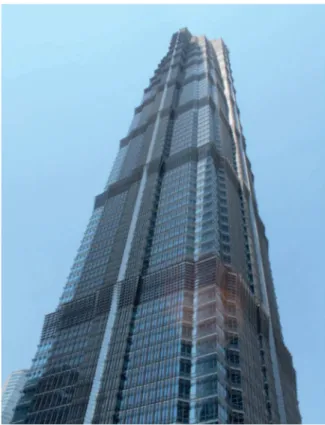
Fig. 1.3 Curtain wall cladding system: unitised system Jin Mao Tower (Shanghai,2019)
Frameless glazing
Frameless glazing, also called spider glazing, is constituted by particular laminated glass panes equipped with connectors in the corners of the glass. These connectors are the join-ts which bolt the glass panes to the stainless steel structure. The applications as external cladding are not very common due to the complex design and the consequent high costs.
Fig. 1.4 Curtain wall cladding system: structural glazing Shanghai Tower (Shanghai,2019)
Fig. 1.5 Curtain wall cladding system: frameless glazing Shanghai Grand Theatre (Shanghai,2019)
• Double skin
The double skin cladding system is characterised by two paralleled layers of envelope which create an air cavity between them. This design allows to enhance the thermal performance of the building. The units of the façade are generally prefabricated and lifted on the construction site.
• Monolithic cladding
Monolithic cladding systems are functional to obtain a seamless façade: the grout lines are covered by two or three layers of sand-cement plaster which create an image of uniformi-ty and continuiuniformi-ty. Generally, the external finishes are made using an acrylic coating in in order to guarantee watertight surface. These systems are often employed in residential con-structions and they are brittle.
• Masonry veneer
The typical masonry veneer cross section is constituted by a single layer of bri-ck. It is allow to have an additional air cavity in order to prevent the water infiltra-tion through the veneer. The air cavity can also provide thermal insulainfiltra-tion. The-se systems are usually employed for low-riThe-se construction with a residential uThe-se.
Fig. 1.7 Monolithic cladding cladding system (Url 7)
• Lightweight panels
Lightweight systems are a wide definition which encompass an ample array of clad-ding panels made of various materials. They include wood, metal and concrete. They are economic envelope solutions and for this reason are commonly employed in diffe-rent uses buildings. Precast concrete panels are included in lightweight panels whether they are characterised by low density, otherwise they belong to heavy panels typology.
• Heavy panels
Heavy panel cladding systems includes concrete and stone cladding panels. Precast concrete panels are the most widespread type used in commercial, residential and indu-strial buildings. Precast concrete panels are examined in depth in the following paragraphs.
Cladding modularity
A module is usually described as a component of a larger system, which collaborates with the other components in order to define the entire system (Steinø, 2017). Although each module has inherent properties, the properties of the whole system are defined by the sum of single unit. Thus, the units’ attributes and the accuracy with which the numerous parts are jointed determine the ultimate performances of the system. Therefore, modularity is the way according to which units can be arranged and divided. Modularity represents for cladding systems the scheme of single panels which constitutes the entire façade. The modularity tells the arrangement of the cladding components and, depending on the layout which the units display, it can be classified differently. The classification of the modularity implies directly how the cladding system show its mechanical, acoustic, energetic, durability performances. The logic applied to describe the different examples of cladding modularity is based on the number of cladding panels which cover a single storey and single bay of a structural frame(Baird, Palermo, Pampanin, Riccio, & Tasligedik, 2011).
• Mono panel
The elementary modularity is identified by the arrangement of the mono panel system. It is formed by a single panel that occupies a single bay. Its characteristics make it indivisible in smaller subsystems.
• Dual panels system
If the mono panel is separated in two equal parts, it becomes a dual panel system. The clad-ding modularity is expressed by two panels with the same width that occupy a single storey and single bay. In this context, the two elements can be organised either horizontally or vertically by twos. However, the most common configuration for cladding systems includes the parallel disposition of two horizontal panels.
• Matrix panels
It is possible to increase the complexity of the modularity dividing the mono panel into more numerous elements, filling the bay of a structural frame with rows and columns. Thanks to this schematisation, the cladding system is described according to a matrix, for instance 4x3 as the following example.
• Spandrel
Another arrangement is constituted by the so-called spandrel. They count precast concrete panels attached only along the beam and/or column lines.
Fig. 1.13 Matrix panels cladding modularity
• Single or multiple punched panels
The last configuration is called punched holes in panels. The most common practice is to punch the panel in the centre obtaining a single opening . Moreover, the single panel can be multiplied several times to obtain multiple openings.
Cladding connections
In precast cladding panels connectors are the essential components of the system. Indeed, they are requested to link the structural frame (breams, pillars etc.) to the cladding panel. Hen-ce, they deserve a specific detailed study because the mechanical behaviour of the cladding panels are strictly related to their performance. Design team must pay attention to the choi-ce of the connector bodies due to the fact it has been seen, thanks to laboratory tests, that they often represent the weakest and least stiff parts of the cladding system. As it is assu-med in Passive control of building response using energy dissipating cladding connections (Pinelli, Craig, Goodno, & Hsu, 1993), there are always five elements which constitute all
movements between the two parts. It is typically realised by steel angles and bolts or other steel components. They can be welded or bolted depending on several design considerations. The classification is carried out according to the different connector bodies: as proposed by Andrew C. Baird, here below it follows the five main typologies. In order to simplify the dis-sertation, it must be noticed that all the technical details about these elements will be avoi-ded, reporting only the prementioned lists with some correlated imagines(Baird, 2014).
• Bearing connection
• Tie-back connection
Fig. 1.16 Examples of bearing connection (PCI, 2007, p. 334)
• Slotted connection
• Fixed connection
Connection modularity
Whether the cladding modularity is more associated to variety and aesthetic considerations, connection modularity responds to safety and loadbearing needs. Connectors are located on the columns, beams, floor and they can also be arranged encompassing two typologies together.
Fig. 1.18 Examples of slotted connection (PCI, 2007, p. 320)
of the panel in the case of column cover panels. Spandrel panels, instead, are connected at the floor level and also to vertical elements.
1.2 Precast concrete panels
Precast concrete panels are one of the most employed cladding technologies across the wold, recording the peaks especially in Asia and North America. In the first instance, their popu-larity depends on the principal material employed for their production: the precast concre-te. In the last decades, the quality of this material is continually rising due to improvemen-ts in proportioning, mixing, placing, finishing, and curing techniques. This advancement has allowed designers and users to benefit of more sustainable developed features, reducing costs and time. Conjunctly to these, appearance, durability, and other important aspects, such as transportation and erection, are steady developing their relevance and quality. Taking advantage of its property of plasticity and workability, concrete allows to design panels with a wide range of shapes and sizes to create architectural variety and enhance the overall ae-sthetic. Thanks to the selection and manipulation of the aggregate, precast concrete panels offer an extended array of patterns, colours, finishes and textures. Moreover, precast concrete has excellent characteristics in terms of thermal-acoustical insulation and fire and blast resistance. In terms of dimensions, concrete panels cover the height of one story, although they are forced to respect standardised width due to transportation and installation limits. Given that these panels are completely reversible, in the case of grave damages they can be replaced easily and, after the substitution, they guarantee all the performance requirements stated for the cladding. Conse-quently, thanks to the excellent durability of precast concrete, maintenance is limited and concen-trated upon single item’s degradation. For precast concrete, the mechanical resistance is another strong point: the panels are designed to resist wind, seismic forces and deformations caused by temperature. Depending on their capacity of bear loads, the precast concrete panels belong to two typologies: the first is non-loadbearing panels and loadbearing wall panels or spandrels. All
Main production phases of a traditional precast concrete panel
1. The first step of production encompasses the formation of the first concrete layer of the fu-ture panel. Initially, an electro-welded mesh and spacers are organized in a mould to cover the requested dimension of the panel. Once casted, the wet concrete is vibrated to obtain a homogeneous thickness. Generally, in big plants, the concrete cast is handled by using a a bridge crane on which is hung up a bucket in charge of spreading the concrete in the for-mwork (Pappalardo, 2018).
2. The second step deals with the installation of the insulation. This phase is managed paying attetion to the joints between the insulating panels in order to prevent heat dispersion and moisture formation.
3. The third step is focused on the production of the structural layer. Following the same practise of the first step, after the cast, the concrete is vibrated and levelled.
4. The last step deals with the curing of the concrete: this phase is essencial to obtain a high quality final panel. To optimise and speed up the process, the panel is immerse in steam or hot air. After the curing, the panel is stored, ready to be transported to the construction site. It is always important to avoid geometrical variations triggered by unexpected stresses pro-duced by general inaccuracy and movements during the ride.
Main characteristics
• Generals
First of all, the speeding up of construction time with a significant reduction in costs have always been the key advantage of prefabrication. This is linked with the possibi-lity of relying on certain time scheduling, the higher executive quapossibi-lity of final product compared to those carried out in on-site procedures. This is allowed thanks to the indu-strial controls which reduces the need of skilled workers on the construction site, repla-cing them with the ease of assembly operations. Another general pro concerns about the relations which are set up among the different performers who are involved in the de-sign of precast concrete: it is essential to establish a close collaboration between archi-tects and the local precast concrete producers starting from the earlier stages of the desi-gn. This teamwork is crucial to obtain high quality products at a minimum assembly cost.
• Flexibility
One of the most forceful features of precast concrete panels is their possibility to be arranged in various ways, both from connections and visual sides. They are totally reversible. They can be attached to the framing with different typologies of joints, especially designed to suit structural and environmental needs. In addition, they can be configured in numerous shapes, dimensions and layouts. Throughout their operational life, they can be removed from the framing to allow the enlargement of the building and then, once completed, they can be reinstalled and flanked with new ones. In case of damages or loss of initial performances, they can be easily repla-ced without undermining the entire construction, reducing costs and rationalising the time.
• Durability
Precast panels durability resides in the concrete mix design and how it is casted. The correct choice of aggregates dimension and the content of water are the two main aspects which carried out an appropriated mix design. In particular, durable concrete components are
reali-This means that, after the cast and when the concrete is still fresh, the mixture can settle and start to become compact (with a low porosity ratio) without the use of vibrators or generally extra manufacturing. All these processes are conducted in the factory, environment where temperature and humidity are constantly controlled in order to ensure the most suitable cu-ring. If all the steps are done in the proper manner, the result will be a highly durable concre-te panels which provide buildings with façades resistant to abrasion, corrosion, weathering, explosions, making it virtually maintenance-free and preserving the building’s original look (PCI, 2007). Prefabrication is the key word for precast concrete panels: indeed, differently from the concrete casted on-site, the concrete panels are undergone to a strict steps of ma-nufacturing control carried out by the precasters. This is the assurance of obtaining an high quality final products because all the plant’s steps are organised to guarantee the best ma-nufacturing ambience such as high degree of relative humidity and controlled temperature.
• Surface Aesthetics
The main aesthetical advantage of precast concrete panel is the enormous variety of cu-stomisation which is available for the design. They have a large creative freedom in terms of architectural language, sizes and shapes. This is allowed thanks to the characteristics of concrete: first of all, in the primary manufacturing steps, its plasticity and its ability to be processed with few work make it perfectly employable to achieve complex visual elements such as textures, bullnoses and ribs. The use of precast concrete mould-building method gi-ves the opportunity to create boundless solutions acting on colour, texture, and other details. For every building is possible to define a various range of aggregates, color tones, textures, and patterns which lend an appearance of strength and novelty. Concrete exhibits an im-pressive aesthetical durability of exterior surface because it does not require painting, being
rantee the harmonisation among the parts. Finally, its plasticity and the infinite shapes that moulds can have allow to model arches, cornices and decorative relief panels at low costs.
• Initial Cost
Once again, the properties of precast concrete and its manufacture are essential to cut costs, in this case the initial cost. The reason is that after the casting and the curing processes the precast panels are already ready to be sent to the construction site and installed to the sup-porting structure. Thus, the overall speed of manufacturing and erection is relevant and the entire building schedule is limited within the year-round. This means that the building enve-lope can be enclosed quickly employing whether loadbearing or cladding panels. This trig-gers many economic advantages such as short-term financing, low construction costs, low management costs throughout the functional life and high potentiality to capitalize the com-pleted building’s value. Another annotation concerns about the savings gained from using loadbearing panels because they do not need the column along the perimeter. This procures extra saving from the littler width of framing and it can be also valid for interior colu-mns which are replaced by additional loadbearing panels, incrementing the overall saving.
• Life Cycle Cost
The life cycle cost is another positive aspect of precast concrete: the choice to resort to in-dustrialised production processes, which use the most efficient technologies and expertise, allows to obtain more savings since serial and large-scale manufacture cost less than on-site one. Designers can outline a precast concrete façade with minimal maintenance due to it does not entail painting. Hence, the relevant initial cost to provide more high-performance components are payed off in long-term durability and preservation of the efficiency, defined during design phase.
• Energy Efficiency
Energy efficiency is strictly related to the performance requirements which the envelope can fulfil. Moreover, the more demanding standards introduced for new constructions force the
designers to get down to work on high energy efficient buildings. To reach that, designers have a vast range of solution they can employ: first it is important to equip precast panels with a suitable thickness of insulation which can be arranged in their backs or be incorpora-ted in the case of sandwich panels. In the same vein, the high thermal mass inertia of concrete is a powerful characteristic which allows to make the indoor temperature stable diminishing the temperature swings. Therefore, there are additional devices which can reduce irradiation peaks and solar gain such as brise-soleil and other shading elements. Also, the characteristi-cs of window frame and glass panes are important to lessen the transmittance value and the thermal control during cold seasons. In order to maximise the efficiency of the envelope, de-signers can typify each face of the façade with specific thermal properties according to the exposure. In addition, the control of air infiltration and exfiltration provides the decrease of the potential moisture problems. Thus, the more the precast concrete panels are energy effi-cient the more it will be possible to reduce heating and cooling costs. This means that thanks to the control of heating peaks and cooling loads is guarantee their translation into cost saving.
• Environmental Impact
It is certified by many assessment models that concrete is an high embodied energy material with a substantial environmental impact. Considering the entire lifecycle, it is essentially due to its manufacturing which is characterised by high consumption of non-renewable re-sources causing consequently a big emission of harmful pollutants (carbon dioxide, sulfur dioxide, nitrogen oxide…). Added to this, once the precast panels are ready to be delivered, there is the transportation and installation phases which contribute to increase the total im-pact. Moreover, arrived at the end-of-life, concrete is difficult to be recycled unless it goes through some processes of milling which make the material employable as an aggregate to
and making as limited as possible the heating loads. On the other side, the same goes for coo-ling loads during summertime. Thus, energy efficiency is linked to low energy consumption (especially non-renewable resources such as oil, coal and gas) which are in turn matched to cost saving. In a certain way, light precast concrete can reflect solar irradiation as well as heat, decreasing the “heat island” effect which is the cause of bad thermal comfort in urban areas. Coming up to the components of precast concrete panels, they use scraps of other indu-stries which previously were landfill items: an example are the mixture cements whi-ch reuse by-products from heavy industry or steel reinforcing bars whiwhi-ch are made from recycled automobile chassis and metallurgic industry. Moreover, in case of mo-dification of the building’s layout, precast panels can be disassembled and successi-vely reattached to the framing, reusing the same non-loadbearing wall panels. Another attribute of precast concrete is that it does not generate no toxic substances during its functional life. It is important to preserve the indoor and outdoor air quality. Final-ly, the precast concrete’s mass is useful also to create a suitable acoustic environment, providing an economical acoustical barrier to exterior and interior noise penetration.
Precast concrete panels used as cladding
The most popular application of architectural precast concrete panels regards non-loadbearing precast concrete panels used as cladding. Non-loadbearing panels are defined as capable of resi-sting their self-weight, wind and seismic forces and of transferring the weight of the panel to the framing structure. As already seen for the numerous typologies of cladding systems, precast con-crete cladding panels can be designed in an ample array of sizes and shapes, typically conside-ring the vertical or horizontal dimensions the longest ones. In terms of bay and storey coverage, cladding wall units are usually equal or smaller than the bay and the storey width of the framing structure. Thus, their width is design according to the structural and architectural requirements: for instance, precast concrete panels are limited to floor-to-floor dimension. Among the main aspects already accounted in the section above, the flexibility of this systems is a bid strong point: in fact, single units can be removed and reinstalled without influencing the stability of the entire façade. The main typology of precast concrete panels as cladding units are:
• Solid wall panels Solid wall panel Ribed panel Lightened panel Sandwich panel • Window wall units • Spandrels
• Solid wall panels
Solid wall panels are the most traditional type of precast concrete unit and they are en-tirely composed by opaque part. This makes them remarkably stiff and strengths re-sistant. Solid wall panels benefit of the principal advantages of precast concrete uni-ts such as the large possibilities of customisation in shape, size, finishes and flexibility.
In order to understand better the large variety of solid wall panels available for the de-sign, it follows here below a brief description of some examples, starting from the most traditional ones to arrive to the latest applications. They will report technical per-formance about thermal insulation. The parameters adopted to compare the degree of panels’ characteristics refer to Italian and Chinese codes1. It must be reminded that the next examples are valid also as samples of window wall units: indeed, window wall pa-nels can be considered as solid wall papa-nels “punched” by a hole which represents the wi-dth of the openings. For this reason, the sequence of layers is similar in both typologies.
1. ITA. Decreto Ministeriale Sviluppo Economico 26 guigno 2015, Applicazione delle metodologie di calcolo
delle prestazioni energetiche e definizione delle prescrizioni e dei requisiti minimi degli edifici. Fig. 1.24 Examples of solid wall panels (Url 14,15)
• Traditional applications
Solid wall panel
Dimensions: Up to 456x221 cm Thickness: 30 cm
This typology is characterised by having reinforced concrete as the core material of the pa-nel. According to its properties, the entire use of reinforced concrete confers more structu-re structu-resistance, without the support of any other layers. The employment of this typology has been used almost in every design application, from residential to industrial and civil constructions. However, this typology suffers from bad thermal and acoustic performance
Monolithic panel in renforced concrete 30 cm
Outside
Ribbed panel
Dimensions: Fixed width 250 cm; hight max 1200 cm Thickness: 14 cm + 30 cm
The main employment of this typology belongs industrial buildings and warehouses. The idea of ribbed panel starts from the shape of horizontal slabs and roof beams made by pre-stressed concrete: instead of using this element as a slab, the designers decided to apply it as a panel useful for creating the external envelop. Due to its application, this panel is not requested to fulfil high energy saving requirements but simply the minimum demanded.
Ribbed panel in renforced concrete Lightened material
Inside
Lightened panel
Dimensions: Width: from 125 to 15 cm. Length: from 250 to 300 cm Thickness: 12 cm
Comparing to the monolithic panels, lightened panels are characterized by a reduced wei-ght thanks to the application of a liwei-ghtened material inside the concrete layer. In addition, depending on the type of lightened material, this panel is able to assure better thermal insulation. In other words, it represents a solution abled to implement the requirements of comfort and thermal qualities in the building.
Outside
Inside
Lightened material Renforced concrete panel
Sandwich panel
Dimensions: Lengh 1000 cm; Height 250 cm Thickness: 30 cm
Sandwich panels are the most employed ones in the housing sector. They stratigraphy is mainly formed by an internal structural layer in reinforced concrete and an external non-structural one. In addition, there are two more layers even if it is possible to joint them in one layer only: the first one is the insulating material that can be modify based on the thermal and sustainable performance that the designers want to guarantee. The second one, that is not necessary, is the lightened material. The internal insulation plays a funda-mental role in terms of improving thermal and acoustic performance. Moreover, thanks to its lightness, this panels can be delivered and lifted easier inside the construction site. The drawbacks are related to the presence of thermal bridges that hit the joint between two panels.
Inside
Outside
Lightened material Insulating material
External renforced concrete pane Internal renforced concrete panel
• Advanced applications
The following examples may be considered as the advanced applications for precast pa-nels. This selection has been reported in the Master Thesis “Pannelli prefabbricati per in-volucro edilizio. Soluzioni alternative” (Pappalardo, 2018) and they have been employed for the realisation of the “Polo Universitario in via Cerola, Milano”. The technical cha-racteristics of these panels have been designed to fulfil the Italian thermal prescriptions (DM 26/6/2015) which are referred to the city of Milan, included in the climate zone E with 2404 heating degree days. The same prescription imposes as maximum wall thermal transmittance value (U-value) 0,26 W/m2K. Even though the city of Shanghai is characte-rised by different climate, with 1623 heating degree days (Deyin, Hongwu, Li, Qiang, Xu, 2017), the following examples may be considered as best practises, available currently on the market, employable in the Chinese context as well. From the comparison between the two cities emerges that their different climate location is the reason of the high discre-pancy between the two thermal transmittance values. U-value for Shanghai is referred to the Chine code CHN. GB 50189-2015, Design standard for energy efficiency of public
Sandwich panel
Dimensions: Lengh from 80 to 320 cm; Height 350 cm Thickness: 30 cm
Physical characteristics
Outside
Internal renforced concrete Polyurethan Gt
External renforced concrete
Inside
Chinese code Italian
code
N° From the interior to
exterior [m]d δ [Kg/m3] λ [W/mK] [m2K/W]R μ -1 Internal renforced concrete 0,12 2500 1,91 0,06 5-10 2 Polyurethan Gt 0,12 25 0,022 5,22 30-150 3 External renforced concrete 0,06 2500 2,08 0,03 5-10 U Thermal trasmittance [W/m2K] 0,18 0,26 0,6
N° From the interior to exterior [m]d δ [Kg/m3] λ [W/mK] [m2K/W]R μ -1 Internal renforced concrete 0,12 2500 1,91 0,06 5-10 2 Insulation in poly-styrene foam
additiva-ted with graphite
0,16 16 0,029 5,52 30-70
3 External renforced
concrete 0,06 2500 2,08 0,03 5-10
Outside Inside
Sandwich panel with insulation in polystyrene foam additivated with graphite
Lengh from 80 to 320 cm; Height 350 cm Thickness: 34 cm Physical characteristics Chinese code Italian code U Thermal trasmittance [W/m2K] 0,17 0,26 0,6
Internal renforced concrete
Insulation in polystyrene foam additivated with graphite External renforced concrete
High performances Misapor concrete
Lengh from 80 to 320 cm; Height 350 cm Thickness: 40 cm
Physical characteristics
MISAPOR concrete Rock wool insulation MISAPOR concrete Chinese code Italian code U Thermal trasmittance [W/m2K] 0,20 0,26 0,6 Outside Inside
N° From the interior to
exterior [m]d δ [Kg/m3] λ [W/mK] [m2K/W]R μ -1 MISAPOR concrete 0,12 120-190 0,27 0,44 5-10
2 Rock wool insulation 0,14 90 0,036 3,89 1
Cellular concrete with closed cell structure
Lengh from 80 to 320 cm; Height 350 cm Thickness: 37,5 cm Physical characteristics Chinese code Italian code U Thermal trasmittance [W/m2K] 0,30 0,26 0,6
Internal renforced concrete
Outside Inside
N° From the interior to
exterior [m]d δ [Kg/m3] λ [W/mK] [m2K/W]R μ
-1 Internal renforced
Sandwich panel with a collection of more sustainable insulation materials
Lengh from 80 to 320 cm; Height 350 cm Thickness: 32 cm
Physical characteristics
Alternative more sustainable insulation materials
Chinese code Italian
code
Other sustainable
inula-tings [m]d δ [Kg/m3] λ [W/mK] [m2K/W]R μ -Wood fiber 0,2 160 0,038 5,3 5 Hemp 0,1 100 0,041 2,4 1,9 Cellular wood 0,2 150-170 0,078 2,6 1,3 U Thermal trasmittance [W/m2K] 0,26 0,26 0,6 Outside Inside
Internal renforced concrete Cork insulation
External renforced concrete
N° From the interior to
exterior [m]d δ [Kg/m3] λ [W/mK] [m2K/W]R μ -1 Internal renforced concrete 0,12 2500 1,91 0,06 5-10 2 Cork insulation 0,14 110-130 0,039 3,50 20 3 External renforced concrete 0,06 2500 2,07 0,03 5-10
• Window wall units
Window wall panels are the most employed type of precast concrete unit and, in the past, they were characterised by a large opaque area. This was triggered by the neces-sity to create a more energy efficient envelope, made from the diminution of windows’ width. This enabled to reduce the dissipation of heat during cold seasons and to limit the solar irradiation during the summer periods. It is also preferable in terms of me-chanical resistance and stiffness: the opaque concrete part acts as a monolithic element which is more solid due to the absence of additional joints. Nowadays, thanks to the enhancement of insulation properties of the glass, it is possible to design ampler ope-nings without having any problem related to structural considerations. A single panel can be “punched” by one or more windows and this provides close tolerances for win-dow installation. According to the needs of the project, they can be flat or sculptured.
sign purpose. This typology of precast concrete panel is particularly appreciated when the designers want to emphasise the linearity or horizontality of a building’s façade, un-derlining consequently its structural frame. Spandrel panels may define each floor crea-ting an easier pattern and rhythm of the building’s prospect. This pattern can be realised by a series of individual units or as one unit of spandrel panels. The aesthetical resear-ch has encouraged the designers to experiment new shapes suresear-ch as those resear-characterised by a vertical tilted profile. This enables the façade to have a unique rhythm and style.
• Column covers and mullions
Column covers and mullions are the alternative solution to underline the structural framing across a building façade. Consequently, running vertically up, they became the major visual scheme in a structure. From dimension prospective, these panels may be of the same width of the column or wider. As state in their name, these units often hide the structural columns and may completely envelope them at the ground level. Depending on their arrangement, column covers can have different sizes but they are usually manufactured in single-story units and spanned either from floor to floor. Mullions should be extended as long as possible to mini-mize erection costs and horizontal joints, always respecting weight and handling limitations.
Size, shape and transportation
Panels have to provide a proper design in terms of size and shape because it af-fects the transportation actions and the in-site construction. There are two main poin-ts that have to be taken into consideration: the first one is the possible damages that the structure can suffer after transportation and the second one is the safety measures whi-ch have to be followed during the entire process, from the factory to the construction site. Thus, the decision regarding the shape and the size of precast concrete panels represents a de-licate design phase. The designers must be particularly conscious of the manufacturing restri-ctions and the crane lifting capacity. Once in the construction site, the major requirement is the safety carried out every transportation phase in order to avoid accidents involving the project operators or other people. To prevent any unpredicted eventuality during the panels delivery,
Depending on the local legislation, if the transport deals with exceptional condition, it must be permitted by the public institution after the positive rate of any overweight and/or overdimen-sion element. In this case, it is requested the intervention of a load pilot to accompany the tran-sport vehicle. This safety measure is useful to signal the protruding dimensions of the precast concrete elements.
Vehicles and trailers
Nowadays there are several trailers employed to carry the precast concrete elements. A point is that it is not always necessary to use specific trailers such as the A-frame trailer or the purpo-se-built trailers, but it is allowed the standard flat-deck vehicle, especially for small elements such as prefab stairs or slabs.
Passing to more accurate vehicles, the most used for carrying precast concrete panels is the A-frame trailer. Although it is simpler than purpose-built trailers, it costs less due to its stiff steel structure upon which the panels are hung up during the delivery. Moreover, there are not any hydraulic items which allow to reduce the maintenance costs. It follows here below same parameters provided by the New Zealand firm Wilco Precast (Wilco Precast, 2018). The para-meters change whether the A-flame trail is flat or low:
« Flat trailer
• Maximum allowable height when loaded of 4800 mm
• Maximum panel size 13500 mm x 3150 mm • No permit up to 4250 height
• Maximum weight 20 tonnes
Low trailer
• Maximum allowable height when loaded of 5400 mm • Maximum panel size 8800 mm x 4150 mm
• No permit up to 4990 mm height
• With permit 5400 (require pilot, power board, traffic police). • Maximum weight 18 tonnes »
The most advanced vehicle for precast concrete transport is the purpose-built trailer. Thanks to its chassis design, the main feature regards the low centre of gravity which consequently allows a safer and more stable vehicle.
As well as the type of trailers, it is important to control the way with which the panels are restrained on transport vehicles to guarantee the highest level of safety. First, every concrete panels must be restrained to prevent any fall from the departure until the construction site. Once reached the right location, the elements must be stable after the release and the unloading phases.
Fig. 1.31 Panels well-restrained configuration (Worksafe New Zealand, 2018, p. 81) Fig. 1.30 A purpose-built trailer (Worksafe New Zealand, 2018, p. 78)
Lifting equilized loads
The panels lifting is the last phase of the transport section. It takes place in the construction site and it needs the same care of the previous operations. It is crucial to follow a precise array of intermediate steps. In order to guarantee the highest level of stability and the balance the wei-ghts, the slings must be applied in the correct way: their application enable to avoid unpleasant cracks. It follows the illustration of two possible lifting methods based on the equalisation of the loads in the slings.
Some references of contemporary applications
Shanghai Baoye Center Location: Shanghai, China Architects: LYCS Architecture Year: 2017
(Url 20)
Burntwood School Location: London
Architects: Allford Hall Monaghan Morris Year: 2014
(Url 16) Morinoie nursery school
Location: Sendai, Japan Architects: Masahiko Fujimori Year: 2017 (Url 21)
2. PERFORMANCE-BASED BUILDING DESIGN (PBD)
APPROACH TO GUIDE THE CHOICE OF
TECNHOLOGICAL SOLUTIONS
What the PBD approach is and how it works
Performance-Based Building Design (PBD) constitutes the methodological approach that establishes the discipline of Architecture Technology. It is applied during the several pha-ses of the building process and the main scope is to fulfil all the stakeholders’ needs to gua-rantee long-term performances during the building functional life. Thanks to the analysis of the needs, it is possible to identify the so-called user needs (UN), considering the regulatory, cultural, environmental and economic restrictions which the designers must to recognise. Once the needs are defined, the designer has the task to translate them into the performance requi-rements (PR), identifying the various characteristics that the different parts of the building must have in order to satisfy the UNs detected. As a result, the overall function assigned to the buil-ding are then divided in singular tasks assigned to the individual parts of the builbuil-ding itself. The-se tasks are expresThe-sed in a number of requirements to which the various elements must respond. For example, the UN for thermal comfort is translated by the designer into nume-rous PRs such as thermal inertia control and heat loss through the wall control as well.
The contemporary performance-based approach has its roots since more than 2000 years ago. One of the most important first written proof was embedded in “De architectura libri decem” (“The Ten Books of Architecture”) which the Roman author Vitruvius submitted to Imperator Caesar (Becker, 2008). The extract claims «the three departments of architecture, […] the art
(Vitruvius, 1 B.C., Book I, Chapter III, section 2).
However, the remarkable novity that Vitruvius presented with his innovative concepts remained only theories until less than 50 years ago. Indeed, during the past centuries, the performance ap-proach adopted was based on «experience-based know-how» (Becker, 2008, p. 2) that was han-ded down from the previous generation to the newest one. Thus, the quality of construction details and the design solutions was only a technical procure, which planted its seeds in comparing the proposed design and executed details with their standardized prescriptions mandated by regula-tions, laws and codes. Because of that, there were not any simulation tools to assess the design. Coming up to the recent evolution, the performance concept in building was first defined by the CIB (International Council for Research and Innovation in Building and Construction) W60 Commission as «first and foremost, the Performance Approach is the practice of thinking and working in terms of ends rather than means. It is concerned with what a building or a buil-ding product is required to do, and not with prescribing how it is to be constructed» (Lee & Barrett, 2003, p.16). The strength of this statement is represented by the way in which most human activities are planned and carried out. Thus, it allows any person not familiar with the building profession to understand that this is the actual manner employed in building as well.
The last definition was formulate in 2005 within the Final Report of Domain 3 “Design of Bu-ildings” of the PeBBu programme and it outlines PBD as «a process in which performance re-quirements are translated and integrated into a building design […]. Performance rere-quirements should express the real user needs behind the question for a built product» (Spekkink, 2005, p. 5). This Report is a further elaboration of the 3rd Domain Report “Bringing Vitruvius up to date”, that was issues in November 2004. It is the product elaborated by 18 different coun-tries which worked four years over 40 Task Members. The introduction of Performance-Based Building Design shows a standardized way of thinking and operating in design that sets up a conceptual framework which allows the definition of simulation tools and test methods appli-cable in the building design assessment process. The PBD framework can be summarised by the following steps.
• Recognise the main stakeholders of the building; • Recognise and define the user needs (UNs)
• Recognise which parts of the building are able to fulfil the UNs recognized • Translate the UNs recognised into PRs
• Recognise performance statistics, such as threshold values or variables that must be reached to consider the requirement satisfied
• Develop suitable design solutions and assessment tools which are able to verify the fulfil-ment the performance criteria.
Main Aspects of the Performance Concept
According to the considerations which are emerged in 2005 within Final Report of Domain 3 of the PeBBu, PBD is focused on two crucial characteristics that are reported as they have been stated:
«1. the use of two languages, one for the demand for the performance and the other for the supply of the performance;
2. the need for validation and verification of results against performance targets.» (Spekkink, 2005, p. 17)
Moreover, as stated in the Report, the demand language is associated to Functional Concept while the supply one is associated Solution Concept. The Functional Concept mirrors the user’s needs, so it declares the function which a building should provide in order to fulfil them. On the other hand, the Solution Concept mirrors the technical needs, so it declares the way with which a building could or should be constructed to satisfy the requirements.
Although there are differences of the meaning between the two concepts, the aim should be to identify clearly and meticulously the needs and requirements according to what are the
objecti-efficient tool which adopts an intermediate language, “performance language”, to match the two Concepts enounced above. Whether from demands point of view functional needs are translated into performance requirements, from supply point of view technical specifications are transla-ted into performance specifications. The first ones deal with the requirements the asset should be intended to use. The second ones are explicated thanks to the characteristics and features associated to the disposed solution. Every translation needs to be validated and assessed throu-gh suitable devices: nowadays the information technology tools are becoming more employed thanks to their power and efficiency. It follows a comprehensive chart which sum up the main components of the PBD. FUNCTIONAL NEEDS TECHNICAL SPECIFICATIONS PERFORMANCE REQUIREMENTS PERFORMANCE LANGUAGE • facily or product related • WHAT: properties required to
enable the intended use USER LANGUAGE
• related to user’s operations • WHY is it required • WHAT is required
PERFORMANCE LANGUAGE • predicted and/or measured
properties of the solutions offered
TECHNICAL LANGUAGE • related to technical solutions • HOW can the requirements
be met
• understood by supply chain partecipants
PERFORMANCE SPECIFICATIONS
COMPARE & MATCH translation
translation
Different scale level of Performance-based approach
The performance-based approach, applied to a building, can be primarily broken up in different levels of scale according to a reiterated procedure. The highest level is occu-pied by the “building as a whole” which means the comprehensive scale of the con-struction. Exactly as it has seen in the previous paragraph, the operative logic is iden-tical for every scale level of the project, starting every time from Functional Concept associated with the demand side which entails a Solution Concept associated with the sup-ply side. Once acknowledged, this method can be replicated for every scale level required.
FUNCTIONAL CONCEPT BUILDING AS A wHOLE BUILDING ELEMENTS BUILDING COMPONENTS BUILDING MATERIALS FUNCTIONAL CONCEPT FUNCTIONAL CONCEPT FUNCTIONAL CONCEPT FUNCTIONAL CONCEPT FUNCTIONAL CONCEPT FUNCTIONAL CONCEPT FUNCTIONAL CONCEPT FUNCTIONAL CONCEPT FUNCTIONAL CONCEPT SOLUTION CONCEPT SOLUTION CONCEPT SOLUTION CONCEPT SOLUTION CONCEPT SOLUTION CONCEPT SOLUTION CONCEPT SOLUTION CONCEPT SOLUTION CONCEPT SOLUTION CONCEPT SOLUTION CONCEPT
Sustainability aspects
Performance-Based Building Design plays an important role in the sustainable construction approach. This is a part of the performance requirements of the building and it can be ful-filed if the design follows the life cycle logic. It is worth spending a few words to descri-be the “building life cycle” which is at the heart of sustainable design approach. Building life cycle can be synthesized in six diachronic phases which are typically illustrated with a circular scheme (ISO 21931-2010, Sustainability in building construction. Framework for methods of assessment of the environmental performance of construction works):
According to the international standard, it is possible to associate each step of building life cycle with the steps of design life cycle and the respective economic assessment tools. There are also three other definitions that are involved in PBD procedure: “service life”, “actual life” and “assessment period” of a building component or an entire building.
The first one is defined as the period after which it is more advantageous to replace a component or an entire building than maintaining it for a longer period. It can be also defined as that part of the life cycle during which the asset is able to guarantee the average level of energy efficiency established during the project. Actual life is the period of time from construction to demolition. Finally, assessment period is the expected operating period of a building or a component. Its
Ra w ma ter ial s up pl y production stages construction process in-use stage end of life stage Trans p o r t Trans p o r t Trans p o r t Man uf a ctur ing C o ns tr uctio n-ins tall a tio n U se Mainten ance R ep air R ep la cement R efur bis hment d ec o ns tr uctio n r ecicl yng/r eus e d is p osal