1
2
3
4
Catalytic secondary methods for
5the removal of tar derived from
6biomass gasification: use of
low-7cost materials and study of the
8effect of sulfur species on the
9steam reforming activity of the
10catalysts
11 12 13 14 PhD candidate Supervisor 15Asbel David Hernandez Marco Scarsella
16 17
ii
Abstract
19
Biomass gasification could potentially mitigate the actual dependency on fossil fuels. The
20
practical application of this technology still faces many challenges to be considered a
21
sustainable and profitable energy production source. One of the drawbacks of this
22
technology is the production of undesirable by-products such as high molecular weight
23
hydrocarbons collectively known as “tar” and sulfur compounds. These unwanted
24
compounds must be removed before syngas end-use applications as they can foul pipes and
25
reduced the performance of equipment downstream the gasifier as well as poison the
26
catalyst used for upgrading the syngas. Catalytic steam reforming stands as an appealing
27
tar removal technology in the small and medium sized gasification plants where heat
28
management is crucial and recovery of the energy content within the tar compounds is
29
desirable avoiding wastewater effluents and disposal of adsorbents. Nickel based catalysts
30
have been the preferred choice in industrial applications for the reforming reactor.
31
However, deactivation by carbon deposition is at present an unresolved problem which
32
must be addressed before commercial application of biomass gasification technology.
33
Moreover, the presence of sulfur compounds even at the low concentration found in most
34
biomass feedstocks is deleterious for the steam reforming activity of the catalyst. This thesis
35
comprises four experimental studies, each of them deal with a specific arguments of the hot
36
gas cleanup technology of biomass syngas. The main focus was on the steam reforming
37
activity of nickel-based catalyst and the effect of sulfur and the potassium-sulfur
38
interactions on the steam reforming performance of the catalyst.
39
The main contributions from these studies are; 1) the development of a less time and energy
40
consuming synthesis procedure for the production of a mayenite-supported nickel catalyst
41
using low-cost precursors. This new method involves the addition of the nickel precursor
42
during the mayenite synthesis procedure. Compared to the “wet impregnation” technique
43
the developed method showed slightly lower toluene steam reforming activity but greater
44
stability, which was ascribed to a higher carbon deposition tolerance. 2) Better
45
understanding on the sulfur poisoning of catalysts under steam reforming conditions at
iii
laboratory scale. The results evidenced that for a deeper knowledge of the sulfur poisoning,
47
the calculation of the sulfur coverage should be more accurate and new methods for its
48
measurement are required. 3) Comprehension of the mechanism of interaction between
49
potassium and sulfur on a sulfur passivated commercial nickel catalyst under reforming
50
conditions using real biomass syngas. The preferential adsorption site for sulfur and
51
potassium was determined for the applied experimental conditions and catalyst and a
52
mechanism involving the interaction of potassium with the sulfur chemisorbed on the active
53
sites was proposed. 54
iv List of figures
55
Figure 1.1 Objective, problem, methodology and expected outcome of the present study. ... 13
56
Figure 1.2 Scope of the thesis. A) Study of low-cost materials for the removal of tar. B) Evaluation
57
of the activity and stability of Ni/mayenite catalysts synthesized from different precursors. C and 58
D) Study of the sulfur poisoning of nickel and rhodium and the K-S interactions ... 16 59
Figure 2.1 General classification of biomass varieties as solid fuel resources according to their
60
biological diversity, source and origin. Adapted from [1]. ... 18 61
Figure 2.2 Schematic of the different steps and processes included in a gasification system.
62
Adapted from [3] ... 22 63
Figure 2.3 Tar maturation scheme. Adapted from [22] ... 24
64
Figure 2.4 Schematic of a Dual Fluidized Bed (DFB) gasifier. Adapted from [38] ... 26
65
Figure 2.5 Schematic of the proposed model for PAH formation during gasification. Adapted from
66
[48]. ... 29 67
Figure 2.6 Simplified schematic of the hot gas cleaning and conditioning process for fuel cell and
68
biofuels applications. ... 31 69
Figure 2.7 Mechanism of tar removal over a carbonaceous surface. Adapted from [63]. ... 34
70
Figure 2.8 Simplified scheme of the possible path of the steam reforming reaction of a metal
71
supported on mayenite according to [101], [93] and [103]. ... 40 72
Figure 2.9 A summary of the different aspects involved in the study of the effect of sulfur
73
poisoning on steam reforming nickel-based catalysts. ... 44 74
Figure 3.1 Experimental set-up used in the study of tar removal using low-cost materials. ... 51
75
Figure 3.2 Experimental set-up used in the study of the activity of different Ni-based catalysts
76
supported on mayenite on the steam reforming of tar model compounds. ... 57 77
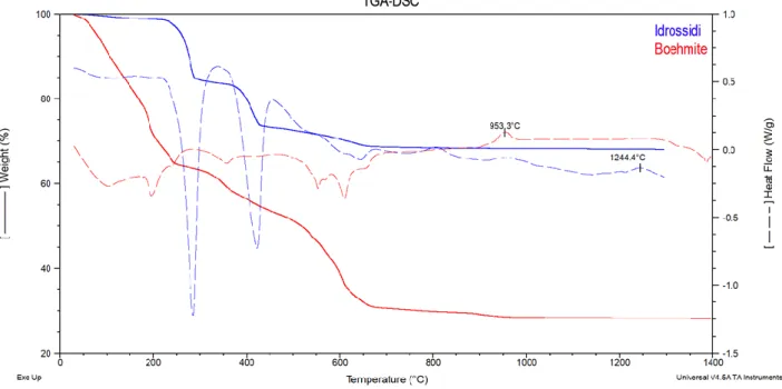
Figure 3.3 TGA-DSC corresponding to the calcination of the precursors of mayenite B and
78
mayenite H ... 59 79
Figure 3.4 Steps for the synthesis of mayenite B, Ni/mayenite B-wi and Ni/mayenite B-os ... 60
80
Figure 3.5 Steps for the synthesis of mayenite H, Ni/mayenite H-wi and Ni/mayenite H-os ... 60
81
Figure 3.6 Atmospheric plug flow reactor used in the study of the effect of sulfur compound on the
82
steam reforming activity of various catalysts. ... 69 83
Figure 3.7 Experimental set-up used in the study of the effect of dosing potassium in the gas phase
84
on the reforming activity of a pre-sulfided commercial Ni/MgAl2O4. ... 75 85
Figure 3.8 Pre-treatment steps applied in the study of the study of the effect of dosing potassium in
86
the gas phase on the reforming activity of a pre-sulfided commercial Ni/MgAl2O4. ... 79 87
Figure 3.9 Schematic representation of the experiments done during the study of the study of the
88
effect of dosing potassium in the gas phase on the reforming activity of a pre-sulfided commercial 89
Ni/MgAl2O4... 80 90
Figure 4.1 tar removal capacity of the bed materials at different temperatures. ... 88
91
Figure 4.2 Deactivation of the tar removal capacity of the bed materials after 3 runs in series of 50 g
92
of biomass each at 700 °C ... 92 93
Figure 4.3 Temperature profile of the three runs at an external temperature of 700 °C. A) Char. B)
94
γ-Al2O3. C) Pumice. D) Activated carbon. ... 93 95
Figure 5.1 XRD patterns of maynetie synthetized by boehmite (A) and hydroxides (B) precursors.
96
M (Ca12Al14O33); C (CaO); N (NiO); CA (CaAl2O4); C3A (Ca3Al2O6); C5A3 (Ca5Al6O14). ... 99 97
v
Figure 5.2 SEM micrographs showing the Ni dispersion on the synthetized catalysts. EDS maps of
98
Ni are included as insets. ... 102 99
Figure 5.3 Temperature programmed reduction (TPR) profiles of the Ni/mayenite catalysts ... 102
100
Figure 5.4 Toluene conversion as a function of time-of-stream (ToS) at 700 °C. ... 106
101
Figure 5.5 SH2 Hydrogen selectivity parameter to identify whether reactions other than those
102
described in the selected reaction network occurred at 700 °C... 107 103
Figure 5.6 Toluene conversion as a function of temperature at S/C=5. ... 107
104
Figure 5.7 𝑘𝑎𝑝𝑝as a function of temperature for Ni/mayenite B-wi, Ni/mayenite H-wi and 105
Ni/mayenite B-os. ... 110 106
Figure 5.8 Arrhenius representation for the kapp values of the steam toluene reforming. ... 112 107
Figure 5.9 (A) XRD patterns of used mayenite. M (Ca12Al14O33); L (CaO); N (Ni); C (CaCO3); C3A 108
(Ca3Al2O6). (B) DTG-TPO profiles of spent catalysts used in the steam reforming of toluene... 112 109
Figure 6.1 Diffractograms of the reduced catalyst. A) Ni/mayenite. B) Ni/Al2O3. ... 121 110
Figure 6.2 A) Impact of the H2S concentration on the benzene and methane steam reforming 111
activity of Ni/Al2O3 at the oven temperatures of 700 °C, 800 °C and 900 °C. B) Temperature 112
measured from the center of the catalyst bed as a function of methane conversion. The zero value 113
on the x and y axis were shifted forward for the sake of readability. ... 127 114
Figure 6.3 A) Impact of H2S on the benzene steam reforming activity of Ni/Al2O3 in the absence of 115
methane at set oven temperatures of 700 °C, 800 °C and 900 °C. B) Temperature measured from the 116
centre of the catalyst bed as a function of benzene conversion. The zero value on the x and y axis 117
were shifted forward for the sake of readability. ... 128 118
Figure 6.4 Regeneration of the benzene and methane steam reforming activity of Ni/Al2O3 after 119
exposure to H2S at 900 °C. The zero value on the x and y axis were shifted forward for the sake of 120
readability. ... 131 121
Figure 6.5 Regeneration of the benzene and methane reforming activity of Ni/Al2O3 at 800 °C and 122
700 °C after exposure to 25 ppm(v) and 10 ppm(v), respectively. The zero value on the x and y axis 123
were shifted forward for the sake of readability. ... 132 124
Figure 6.6 Benzene conversion as function of the catalyst temperature for the Ni/Al2O3, 125
Ni/mayenite and Rh/Al2O3 catalysts in the presence of thiophene. The zero value on the y axis were 126
shifted forward for the sake of readability. ... 136 127
Figure 6.7 Regeneration of the methane steam reforming activity of Ni/Al2O3 after exposure to 128
benzene-thiophene mixture at 900 °C. ... 139 129
Figure 6.8 Regeneration of the water gas shift activity of Ni/Al2O3 and Ni/mayeniteafter exposure 130
to 100 ppm(v) of H2S at oven temperatures of 700 °C, 800 °C and 900 °C. The zero value on the x 131
and y axis were shifted forward for the sake of readability. ... 141 132
Figure 6.9 A simplified scheme of the sulfur-passivated catalyst on the benzene steam reforming in
133
the presence of H2S or thiophene and its regeneration in a sulfur-free H2-rich feed stream. ... 144 134
Figure 7.1 The changes in BET surface area of the catalyst and support after the pretreatment and
135
after the saturation and decay phases with respect to the fresh. ... 148 136
Figure 7.2 normalized sulfur and potassium content of the fresh catalyst and the support and after
137
the pretreatment, saturation and decay phases... 150 138
Figure 7.3 CH4 conversion as a function of ToS during the saturation and decay phases. ... 152 139
Figure 7.4 Conversion of C2H4 as function of ToS during the saturation phase and decay phase . 154 140
Figure 7.5 Conversion of C10H8 during the saturation and decay phases ... 156 141
vi
Figure 7.6 H2 molar flow formation as a function of ToS. Calculated as the difference between the 142
measured H2 molar flow rate at the outlet and inlet of the reforming reactor ... 158 143
Figure 7.7 Proposed mechanism for the interaction and impact of K on the S-passivated
144
Ni/MgAl2O4 under steam reforming conditions. ... 160 145
146
List of tables 147
Table 2.1 Proximate and Ultimate analyses of biomass and coal [18] ... 20
148
Table 2.2 Specifications and average values of tar of the main type of gasifiers [46], [47] ... 27
149
Table 2.3 Maximum allowable levels of impurities in syngas for chemical synthesis. Adapted from
150
[27]. ... 30 151
Table 3.1 Experimental conditions in the study of tar removal using low-cost materials. ... 52
152
Table 3.2 Proximate and ultimate analysis of the olive pomace used in the study. ... 53
153
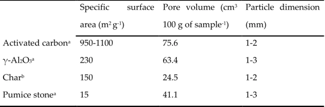
Table 3.3 Properties of the materials used in the study of tar removal using low-cost materials. ... 54
154
Table 3.4 Experimental conditions used in the study of the activity of different Ni-based catalysts
155
supported on mayenite on the steam reforming of tar model compounds. ... 58 156
Table 3.5 Inlet composition used in the experiments of the effect of sulfur compounds on the steam
157
reforming activity of various catalysts. ... 70 158
Table 3.6. Experimental conditions used in the study of the effect of dosing potassium in the gas
159
phase on the reforming activity of a pre-sulfided commercial Ni/MgAl2O4... 76 160
Table 3.7 Proximate and ultimate analysis of the pine pellets. ... 77
161
Table 3.8 Mears criterion values estimated based on the values obtained at the beginning of the
162
decay phase. ... 83 163
Table 4.1 Tar removed at different temperatures after 50 g of biomass fed to the pyrolysis reactor.
164
... 87 165
Table 4.2 Average CO, CO2, CH4 and H2 volume per gram of biomass obtained during the test 166
carried out at 700 °C ... 88 167
Table 4.3 Tar removed after each of the three runs of 50 g of biomass fed to the pyrolysis reactor. 91
168
Table 4.4 Coke deposited on the materials after the deactivation experiments ... 91
169
Table 4.5 Average total gas volume on N2-free basis per gram of biomass and average H2 volume 170
per gram of biomass ... 95 171
Table 5.1 BET-BJH data for fresh catalysts ... 101
172
Table 5.2 Catalyst properties after H2 temperature-programmed reduction (TPR) experiments .. 104 173
Table 5.3 Total dry gas flow rate (N2-free basis) and main non-condensable gases measured at the 174
outlet of the reactor at different temperatures. ... 109 175
Table 5.4 Kinetic parameter for Ni/mayenite B-wi, Ni/mayenite H-wi and Ni/mayenite B-os. ... 111
176
Table 5.5 Average crystallite size of the NiO particles and carbon deposited per unit mass of
177
catalyst. ... 115 178
Table 5.6 Carbon deposited values in addition to the main experimental conditions applied in the
179
corresponding experiment. ... 116 180
Table 6.1 Catalysts properties estimated from the H2 chemisorption characterization ... 122 181
Table 6.2 Sulfur coverage and the corresponding benzene conversion on Ni/Al2O3 catalyst at 182
different H2S concentrations at oven temperatures of 700 °C, 800 °C and 900 °C ... 124 183
vii
Table 6.3 Conversion of thiophene and benzene and CO2 volume fraction in outlet gas for the 184
catalysts studied. ... 134 185
Table 7.1 C6H6 conversion the corresponding H2 formation assuming complete steam reforming 186
reaction to CO and H2 ... 158 187
Table 7.2 Specific carbon content after the different pretreatments and phases (saturation and
188
decay) of the study. ... 162 189
Table of contents
1 Setting the scene ... 11
1.1 Scope of the thesis ... 12
1.2 Summary of the experimental studies ... 13
1.3 Thesis outline ... 17
2 Introduction ... 18
2.2 Biomass and biofuels ... 18
2.3 Biomass gasification for fuel cells and biofuel applications ... 20
2.4 The dual fluidized bed gasifier (DFB) ... 25
2.5 Formation of polycyclic aromatic hydrocarbons (PAH) ... 28
2.6 Syngas conditioning ... 29
2.7 Poisoning of nickel steam reforming catalyst by sulfur species ... 40
2.8 Potassium interaction with nickel-based steam reforming catalysts ... 45
2.8.1 Potassium-Sulfur interaction on nickel-based steam reforming catalysts ... 47
3 Experimental part ... 50
3.1 Coarse tar removal using readily available low-cost materials ... 50
3.1.1 Experimental set-up and experimental conditions ... 50
3.1.2 Materials and methodology ... 52
3.1.3 Data treatment and analysis ... 54
3.2 Steam reforming of toluene as tar model compound on Ni/mayenite synthesized using innovative procedures. ... 56
3.2.1 Experimental set-up and experimental conditions ... 56
3.2.2 Materials and methodology ... 58
3.2.3 Data treatment and analysis ... 62
3.2.4 Kinetic modelling... 64
3.3 Effect of H2S and thiophene on the steam reforming activity of Ni/Al2O3, Ni/mayenite and Rh/Al2O3. ... 68
3.3.1 Experimental set-up and experimental conditions ... 68
3.3.2 Materials and methodology ... 71
3.3.3 Data treatment and analysis ... 72
3.4 Effect of adding a KCl aerosol on the reforming activity of a pre-sulfided commercial Ni/MgAl2O4... 74
3.4.1 Experimental set-up and experimental conditions ... 74
3.4.2 Materials and methodology ... 76
3.4.3 Data treatment and analysis ... 80
3.4.4 External mass transfer limitations ... 82
4 Coarse tar removal using readily available low-cost materials ... 84
4.1 Effect of the temperature on the tar removal capacity of the materials ... 86
4.2 Deactivation of the material with time on stream ... 89
4.3 Summary ... 96
5 Steam reforming of toluene as tar model compound on Ni/mayenite synthesized using innovative procedures. ... 97
5.1 Fresh catalyst characterization ... 99
5.2 Steam reforming of toluene (STR) ... 104
5.3 Kinetic parameters ... 109
5.4 Characterization of the spent catalysts ... 112
5.5 Summary ... 117
6 Effect of H2S and thiophene on the steam reforming activity of Ni/Al2O3, Ni/mayenite and Rh/Al2O3. ... 119
6.1 Fresh catalyst characterization ... 120
6.2 Sulfur coverage calculations (θs) ... 123
6.3 Effect of H2S on steam reforming performance of Ni/Al2O3 ... 125
6.4 Poisoning and regeneration of Ni/Al2O3 catalyst ... 130
6.5 Steam reforming of a thiophene-containing simulated COG stream ... 133
6.6 Effect of H2S on the Water gas shift reaction (WGS) ... 139
6.7 Summary ... 143
7 Effect of adding a KCl aerosol on the reforming activity of a pre-sulfided commercial Ni/MgAl2O4. ... 145
7.1 Fresh and spent catalyst characterization ... 147
7.2 Preferential adsorption site for K and S ... 148
7.3 Influence of K aerosol addition to the steam reforming performance of the sulfur-passivated Ni/MgAl2O4 and role of the support on the total conversion of CH4, C2H4 and C10H8 ... 150
7.4 Proposed mechanism for the K interaction with the S-passivated Ni/MgAl2O4 under realistic steam reforming conditions. ... 159
7.5 Carbon deposition on the catalyst and support ... 161
7.6 Summary ... 162
9 Acknowledgments ... 167 10 References ... 168
Setting the scene
11
1 Setting the scene
1 2
Currently, roughly 80 % of the world total primary energy supply is from fossil fuel sources
3
such as oil, natural gas and coal [1]. Concerns exist regarding access to adequate, affordable,
4
and reliable energy supplies and accelerated rates of climate change caused by greenhouse
5
gas emissions from fossil fuel combustion are driving interest in renewable energy sources
6
such as solar, wind, biomass, and geothermal [2]. The transition from fossil fuels towards
7
the integration of more and more renewable energy requires rethinking and redesigning the
8
energy system both on the generation and consumption side [3]. This process requires
9
alternative production chains of renewable substitutes, as well as combined actions such as
10
changes in behavior, changes in vehicle technology and development of public
11
transportation [4]. The purpose of introducing more and more renewable energy into the
12
energy system is to save fuels, which in the short term are fossil fuels (and nuclear in some
13
contexts). In the longer-term bioenergy will become the key concern, as biomass is a limited
14
resource that cannot be expected to replace all fossil fuels used today, in other words, it is
15
equally important to limit the use of energy by recycling, reusing and reducing wastes and
16
using more efficient technologies [3]. Bioenergy can be converted from biomass via two
17
main types of processes: thermochemical and biochemical/biological processes [5].
18
Generally, thermochemical processes have higher efficiencies and the superior ability to
19
destroy most of the organic compounds. [5]. Regardless of the technology applied, biomass
20
conversion to energy could provide a sustainable waste management practice [6].
21
Potential thermochemical processes to produce bioenergy are gasification and pyrolysis.
22
Biomass gasification has attracted the most attention because it offers high carbon
23
conversion efficiency and high flexibility in using different kind of feedstock materials as
24
well as in the generation of different intermediate products for upgrading to high-value end
25
products such as hydrogen and biofuels e.g. methanol, dimethyl ether, Fischer-Tropsch and
26
synthetic natural gas (SNG) [7]. Globally, 52 countries have set targets and mandates for
27
biofuels [8]. However, the commercialization of advanced biofuels have experienced
Scope of the thesis
12
financing gaps due to high specific investment costs, uncertainty about the stability of
29
policies and lack of knowhow in sourcing and conversion of biomass [8]. Regarding the
30
conversion of biomass through the gasification technology, formation of heavy
31
hydrocarbons (referred to as tar) and release of inorganic species such as potassium and
32
sulfur represent the main obstacle for the efficiency and profitability of the process and it
33
needs to be addressed. A promising way to mitigate tars is the catalytic reforming of the
34
raw gas from the biomass gasifier at temperatures close to the former operating
35
temperature, which allow a more efficient performance and the conversion of the tar species
36
to useful permanent gases i.e. H2, CO, CO2 [9]. The presence of small amounts of sulfur in
37
the biomass feedstock will negatively affect the performance of the catalyst in the reformer
38
reactor, this effect has been known for many years and several countermeasures have been
39
proposed such as promotion of the catalyst of changes in the operating conditions of the
40
reformer [10]–[12]. Moreover, formation of carbon deposits on the catalyst surface along
41
with the production of permanent gases during the reforming reactions can have
42
detrimental consequences of the overall performance and profitability of the process [13].
43
Therefore, the need for a better understanding of the biomass tar reforming process focusing
44
on the stability of the catalyst and its tolerance against sulfur and carbon formation is
45
fundamental to improve the utilization of biomass and boosted the production of biofuels
46
1.1 Scope of the thesis
47 48
The scope of this thesis is the experimental study of secondary hot gas cleaning
49
measurements, specifically, adsorption and conversion of high molecular aromatic species
50
and the catalytic steam reforming of tar species produced from the gasification of biomass.
51
Additionally, the impact of sulfur and K-S interaction on the steam reforming performance
52
of the catalyst was assessed. The objective, problem, methodology and expected outcome
53
are depicted in Figure 1.1
Setting the scene
13 55
Figure 1.1 Objective, problem, methodology and expected outcome of the present study.
56
1.2 Summary of the experimental studies
57 58
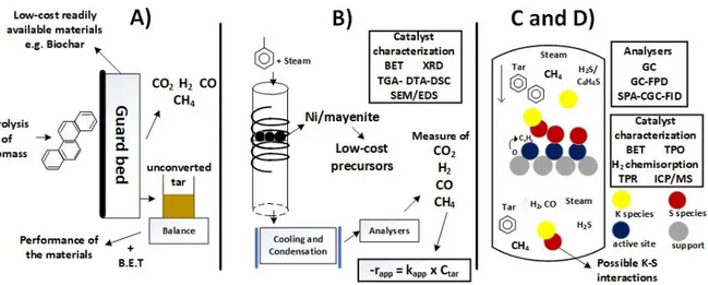
The first study concerns the evaluation of different low-cost readily available materials for
59
the initial coarse removal of tar that can be used as a guard bed to extend the life of the
60
nickel catalyst in the downstream reformer. In this study the low-cost material tested
61
namely char from olive residue, commercial activated carbon (Aquacarb 207 EA), γ-Al2O3
62
(Sigma Aldrich) and pumice stone (JT Baker), were exposed to the raw gas from the
63
pyrolysis of olive residue. Measurements of H2, CO, CO2, CH4 and dry gas volume along
64
with gravimetric analysis of the unconverted tar after condensation were carried out to
65
examined the removal performance of the materials. Evaluation of the extent of
66
endothermic reaction occurring on the materials was indirectly performed by measuring
67
the temperature at the middle of the bed. Deactivation of the materials tar removal capacity
68
Objective
•Catalytic secondary hot gas cleaning of biomass Syngas produced in fluidized bed gasifiers for biofuels and fuel cells applications. Problem •Catalyst deactivation due to carbon deposition caused mainly by the presence of tar compounds and traces of sulfur species. Methodology •Lab-scale experimental work. •Use of low-cost
materials for a coarse removal of tar. •Tests of Ni-based catalysts supported on mayenite synthesized from readily available precursors in the SR reaction of tar compounds. The effect of the nickel addition methos was investigated
•Study of the impact of sulfur and S-K
interactions on the SR catalyst performance
Expected otucome
•Determine the more suitable low-cost material for rough tar removal, considering the operating conditions and availability.
•Assess the possibility of employ an innovative synthesis procedure for the production of mayenite as a stable support for Ni catalysts on the SR of tar compounds. Shed light on the effect of the nickel addition method on the catalytic performance •Gain insight on the
effect of sulfur poisoning and K-S interactions that help establishing optimal operating condition to prolong the catalyst life.
Summary of experimental studies
14
was explored. The limitations of the experimental set-up were identified. A graphical
69
abstract of this study is shown in Figure 1.2 A.
70
The second study of the thesis refers to the assessment of the activity and stability of
71
different nickel-based catalysts on the steam reforming of toluene as model tar compound.
72
The catalysts are constituted of nickel as the active metal supported of mayenite. It was
73
shown in a previous work carried out in the same setup that Ni/mayenite [14] has high
74
activity for the steam reforming of hydrocarbons as well a good stability towards the coke
75
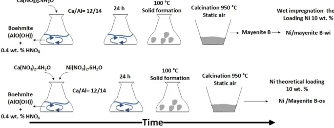
formation. Four nickel/mayenite catalysts were prepared starting from two methods
76
consisting in the use of different precursors, namely boehmite + CaNO3 and gibbsite +
77
Ca(OH)2. The effect of the Ni addition method was also evaluated, comparing wet
78
impregnation on the mayenite and direct inclusion of nickel precursor during the mayenite
79
synthesis. The as synthesized catalysts were evaluated based on activity and stability for the
80
steam reforming of toluene. A simplified first order kinetic model was used to obtain the
81
kinetic parameters. Characterization of the fresh and spent catalysts (XRD, BET, SEM/EDS
82
and TGA) was conducted to examined structural and morphological properties of the
83
materials and related them to the steam reforming activity results. Figure 1.2 B illustrates a
84
graphical abstract of this study.
85
The third study of this thesis was conducted at VTT Technical Research Centre of Finland
86
and deals with the sulfur poisoning of three catalysts, namely Ni/Al2O3, Ni/mayenite and
87
Rh/Al2O3 on the steam reforming of benzene and methane present in a H2-rich feed stream
88
using H2S concentrations typically found in syngas from biomass gasification. Sulfur
89
poisoning of the catalyst on the benzene steam reforming reaction were carried out at the
90
same temperature as in sulfur-free experiments and the effect of the temperature on the
91
benzene conversion of the poisoned catalyst was closely related to the sulfur chemisorption
92
equilibrium and free active sites since already at the lowest temperature investigated the
93
benzene conversion was close to 100 %. Sulfur coverage (θs) was calculated and correlated
94
with benzene conversion at different temperatures. Regeneration tests in a sulfur-free H2
-95
rich feed stream were performed. Water-gas shift poisoning, and regeneration was studied
Setting the scene
15
as function of temperature in a hydrocarbon-free feed stream. The total sulfur capacity of
97
the bed was calculated based on the H2-chemisorption analysis and it was used to have a
98
rough approximation for the timeframe of total deactivation of the bed.
99
The fourth study was carried out at KTH Royal Institute of Technology and was a follow up
100
of a detailed experimental work started by Pouya H. Moud [15] on the investigation of the
101
effect of dosing potassium in the gas phase on the reforming activity of a pre-sulfided
102
commercial Ni/MgAl2O4 HT-25934 Haldor Topsoe A/S catalyst steam reforming activity.
103
The feed was obtained from the gasification of pine pellets in an oxygen blown bubbling
104
fluidized bed (BFB) gasifier. Before the reaction the catalyst and the support of support i.e.
105
MgAl2O4 Haldor Topsoe A/S were mixed with an inert material and pre-treated in a
106
sequence involving; reduction, ageing and sulfidation using a H2S/H2 ratio similar to the
107
one present in the producer gas from the gasifier following the procedure developed by
108
Pouya H. Moud [15]. Subsequently, the catalyst and support were exposed, simultaneously,
109
to the producer gas and a KCl aqueous solution fed with an aerosol generator, during this
110
period naphthalene was measured along with the non-condensable gases e.g. H2, CO, CO2,
111
CH4, C2H4 and N2. Afterward, the catalyst and support were separated, and the reaction was
112
carried out again for the catalyst and the support without the KCl addition. Characterization
113
of the catalyst and support were conducted during all the phases of the experimental work.
114
Based on the results a model of the interaction mechanism of potassium on the sulfided
115
catalyst during the steam reforming reaction was proposed.
116
A graphical abstract of the third and four parts of the present study is presented in Figure
117
1.2¡Error! No se encuentra el origen de la referencia. C and Figure 1.2 D. 118
Summary of experimental studies
16 119
Figure 1.2 Scope of the thesis. A) Study of low-cost materials for the removal of tar. B) Evaluation of the activity and
120
stability of Ni/mayenite catalysts synthesized from different precursors. C and D) Study of the sulfur poisoning of nickel 121
and rhodium and the K-S interactions 122
In conclusion the general scope of the thesis is to a have a better understanding of the tar
123
compounds removal and conversion at temperatures close to the exit temperature of
state-124
of-the-art fluidized bed biomass gasifiers using catalytic steam reforming technologies,
125
focusing on the role of sulfur and potassium-sulfur interactions on the steam reforming
126
activity of nickel-based catalysts. The contribution of this work is an insightful study of the
127
sulfur poisoning on the catalyst steam reforming performance under conditions i.e.
128
concentrations and temperatures, similar as those encountered in real biomass
producer-129
gas streams. Evaluation of the temperature effect of the sulfur poisoning was isolated from
130
temperature effect on the steam reforming activity under sulfur-free conditions. Sulfur
131
tolerance of the steam reforming and water-gas shift reaction were examined together to
132
shed light on the extent of poisoning of both reactions under the same conditions. Moreover,
133
the impact of gas-phase addition of potassium on an aged and sulfided commercial catalyst
134
have been reported only by Pouya. Moud [16] before and a deep understanding thereof can
135
have significant implications on commercial applications. The latter study forms the
136
foundation for a detailed in-situ dynamic investigation of the potassium desorption kinetics
137
from an aged and sulfided nickel catalyst under steam reforming conditions that will result
138
in a clearer picture of the role of gas-phase potassium and therefore an accurate
139
interpretation of the possible implications on commercial applications. Preferential
140
adsorption sites for sulfur and potassium were examined. The role of the support and the
Setting the scene
17
effect of gas-phase reactions caused by the presence of K species on the overall hydrocarbon
142
conversion was evaluated.
143
1.3 Thesis outline
144 145
As described above the thesis consists of four experimental studies conducted during the
146
three years of career. First an introduction part (chapter 2) is given to review the biomass
147
gasification technology, focusing on the gas conditioning steps, the sulfur poisoning on
148
nickel steam reforming catalyst and the effect of potassium addition of the catalyst as well
149
as the sulfur-potassium interactions under steam reforming conditions. In chapter 3 a
150
description of the experimental setup, materials, methodology as well as the data treatment
151
is provided. This chapter is divided in four sections, each for every study. For the sake of
152
readability and also considering the different arguments dealt on each study the results and
153
discussion part of these studies is presented in dedicated chapters (from chapter 4 to 7).
154
Finally, in chapter 8 final conclusions and recommendations are given based on the
155
discussion of the results and also on the experience gained throughout the career.
Introduction
18
2 Introduction
157 158
2.2 Biomass and biofuels
159 160
Biomass is contemporaneous (non-fossil) and complex biogenic organic–inorganic solid
161
product generated by natural and anthropogenic (technogenic) processes, and comprises:
162
(1) natural constituents originated from growing land- and water-based vegetation via
163
photosynthesis or generated via animal and human food digestion; and (2) technogenic
164
products derived via processing of the above natural constituents [17]. The general
165
classification of biomass varieties as fuel resources can be divided preliminary and roughly
166
into several groups, which are depicted in Figure 2.1
167
168
Figure 2.1 General classification of biomass varieties as solid fuel resources according to their biological diversity, source
169
and origin. Adapted from [1]. 170
Biomass
Wood and
woody and agriculturalHerbaceous Aquatic
Animal and human wastes
Contaminated biomass and industrial wastes
Biomass and biofuels
19
Biomass fuels or biofuels are technogenic solid, liquid or gaseous fuels generated from
171
natural biomass resources via some processing. Respectively, the bioenergy is the energy
172
produced from biomass fuels [17].
173
Unfortunately, most of the biomass wastes is used very inefficiently with adverse impacts
174
on public health, therefore, a significant longstanding need for improved bioenergy
175
technologies in the developing world is needed. Recently, there has been renewed interest
176
in the industrialized world in the potential for bioenergy to mitigate global climate change
177
and for liquid biofuels to substitute for expensive imported oil [18].
178
In terms of biofuels technologies, the most important areas for research, in terms of
179
sustainability, are those that enable the use of lignocellulosic as well as aquatic, animal-,
180
human- and industrial-waste feedstocks i.e. second-generation biomass, and yield
high-181
quality liquid fuels, such as bio-based hydrocarbons. However, the use of aquatic, animal-,
182
human- and industrial-waste biomass feedstocks it is challenging due to the presence of
183
high quantities of contaminants such as heavy metals, sulfur and alkali metals and volatile
184
matter with respect to softwood.
185
The chemical composition of biomass is highly variable as determined by proximate,
186
ultimate and particularly ash analyses. When the proximate and ultimate data are
187
recalculated respectively on dry and dry ash-free basis, the characteristics show quite
188
narrow ranges. This is due to the extremely high variations of moisture, bulk ash yield and
189
different genetic types of inorganic matter in biomass [17]. In ¡Error! No se encuentra el
190
origen de la referencia. the proximate and ultimate analyses are presented for some types 191
of biomass. It should be noted that the numbers listed in ¡Error! No se encuentra el origen
192
de la referencia. are average values, the standard deviation can be very large due to use of 193
unsuitable scientific approaches, incomplete data or unusual and sometimes inappropriate
194
terms that lead to inaccurate interpretations and misunderstandings about the biomass and
195
biomass fuels [9], [17].
Introduction
20
Table 2.1 Proximate and Ultimate analyses of biomass and coal [18]
197
Feedstock Proximate analysis, wt. % Ultimate analysis, wt. % (daf) Net calorific value, MJ kg-1 Moisture Ash, (dry) FC (daf) VM (daf) C H N S O Black liquor Softwood MSW Bituminous coal 6.7 4.7 6.1 3.0 36.5 1.7 16.8 9.6 16.4 25.7 12.7 62.1 83.6 74.3 87.3 37.9 40.9 53.4 59.2 82.0 7.9 5.8 9.8 5.3 0.2 0.4 2.2 1.4 6.9 0.03 0.3 0.4 56.5 40.3 28.5 10.9 20 18.4 22.5 31.2 198
In general, biomass has higher oxygen content and thus has a lower net calorific value than
199
coal. In addition, the higher volatile matter content in biomass compare to coal translates in
200
the formation of high quantities of organic condensable compounds under gasification
201
conditions.
202
Improved policies, detailed cycle-assessments and techno-economic analysis and increased
203
knowledge in technologies that permits the use of second-generation biomass to produce
204
energy could render the gasification of biomass a sustainable and competitive way to
205
produce electricity, heat, biofuels and biochemicals, in the short-to-middle term.
206
2.3 Biomass gasification for fuel cells and biofuel applications
207 208
The first step of the gasification of biomass is called pyrolysis and consists in the conversion
209
of biomass by the action of heat in an inert atmosphere into char, gas and a liquid composed
210
of a mixture of hundreds of oxygenated organic compounds [19]. According to the Waterloo
211
mechanism the pyrolysis of biomass is most frequently considered as the superposition of
212
three main primary mechanisms, namely char formation (dehydration), depolymerization
213
and fragmentation [20]. The proportion of products formed is strongly dependent on the
214
reaction temperature and time, and on the heating rate [21]. In general, low process
Biomass gasification for fuel cells and biofuel application
21
temperature e.g. 350 °C, and long vapor residence time increase the char yield, whereas high
216
temperature e.g. 750 °C, and long residence time increase the gas yield. Moderate
217
temperature e.g. 550 °C and short vapor residence time e.g. tenths of seconds, favors
218
production of liquids.
219
Biomass gasification is a complex combination of pyrolysis and partial oxidation of
220
carbonaceous materials in the condensed and vapor phases in the presence of an oxidizing
221
agent that may be pure oxygen, steam, air or combinations of these [22]. The interest in
222
biomass gasification arises from the fact that H2 and CO carries more than 70 % of the energy
223
stored in the biomass feedstock [23]. Historically, It appears that interest in gasification
224
research correlates closely with the relative cost and availability of liquid and gaseous fossil
225
fuels [24].
226
The result of the gasification is a fuel gas - the so-called syngas - consisting mainly of carbon
227
monoxide (CO), hydrogen (H2), carbon dioxide (CO2), water vapor (H2O), methane (CH4),
228
nitrogen (N2) C2 hydrocarbons in relatively low amounts and contaminants, such as carbon
229
particles, tar and ash [24]. The original chemical composition of the biomass feedstock along
230
with the design, gasifying agent and operating conditions of the gasification reactor
231
determine the relative amounts of the by-products and contaminants in the raw gasifier gas
232
[23]. The term “tar” does not have a generally accepted definition [22]. According to Devi et
233
al [25], Tar is a complex mixture of condensable hydrocarbons produced under thermal or partial
234
oxidation regimes, comprising single-ring to 5-ring aromatic compounds plus other oxygen-235
containing hydrocarbons and complex polycyclic aromatic hydrocarbons (PAHs). 236
The main chemical reactions taking place during the thermochemical conversion in a
237
biomass gasifier can be summarized as follows [26]:
238
Pyrolysis process
239
Biomass → Char(C) + CO + CO2+ H2O + H2+ tar
+ light hydrocarbons
∆Hr0 < 0
at high heating rates [6]
Eq. 2.1
Oxidation process
Introduction 22 C +1 2O2→ CO ∆Hr0= −109 KJ/mol Eq. 2.2 H2+ 1 2O2 → H2O ∆Hr 0= −242 KJ mol Eq. 2.3 Reduction process 241
C + CO2↔ 2CO (Reverse Boudouard) ∆Hr0= 172 KJ/mol Eq. 2.3
C + H2O → CO + H2 (Water gas reaction) ∆Hr0= 131 KJ/mol Eq. 2.4
CH4+ H2O → CO + 3H2 (Steam reforming) ∆Hr0= 159 KJ/mol Eq. 2.5
CO + H2O → CO2+ H2 (Water-gas shift) ∆Hr0= −42 KJ/mol Eq. 2.6
CO + 3H2→ CH4+ H2O (Methanation) ∆Hr0= −206 KJ/mol Eq.2.7
242
The application of biomass gasification technology strongly depends on syngas quality
243
requirements for the end-use application and economic factors such as intended production
244
scale and subsidies.
245
The schematic in Figure 2.2 illustrates the different possible applicable processes in a
246
gasification system depending on fuel selected, gasification technology as well as
247
downstream application.
248
249
Figure 2.2 Schematic of the different steps and processes included in a gasification system. Adapted from [3]
Biomass gasification for fuel cells and biofuel application
23
There are generally two gasification technologies suitable for production of high calorific
251
syngas from biomass, either by using an entrained flow gasifier at a high temperature of
252
1300 °C, or using a fluidized bed gasifier together with a downstream catalytic reformer,
253
both operating at around 900 °C [27]. The two technologies have different degree of
254
maturity. Entrained flow gasifiers are a proven concept in case of coal as a fuel, but biomass
255
is not suitable to be directly injected to the reactor and therefore pre-treatments, such as
256
torrefaction or pyrolysis are needed. In case of fluidized bed gasification, the technology is
257
developed and already demonstrated with biomass to produce heat and/or electricity [9].
258
Heat needed for the endothermic reactions may be supplied internally in the gasifier by
259
controlled partial combustion as expressed in ¡Error! No se encuentra el origen de la
260
referencia.. Heat can also be provided externally by superheated steam, heated bed
261
materials or by burning some of the char or gases separately [27]. Examples of large-scale
262
fluidized bed biomass gasifiers, which have demonstrated a prolonged period of operation
263
and have been delivering a raw gas that has been conditioned into a pure synthesis gas, are
264
the Repotec gasifier in Güssing, Austria, and the Andritz Carbona gasifier in Skive,
265
Denmark. However, the lower gasification temperature in the fluidized bed case results in
266
a syngas still containing significant amounts of tar that first needs to be removed or
267
converted to syngas before additional gas conditioning, purification, and conversion to
268
chemicals or fuels. If the tarry raw syngas is left untreated, condensation of tar at low
269
temperatures i.e. 400 °C, may occur downstream the gasifier, leading to plugging and
270
fouling issues [28]. Even at very low concentrations, tars in the syngas may result in coking
271
of catalysts in downstream gas upgrading processes [29].
272
Figure 2.3 shows the transition as a function of process temperature from primary products 273
to phenolic compounds to aromatic hydrocarbons. The description of process changes
274
should be a function of reaction severity, which combines both temperature and time.
275
Another important factor is the importance of gas-phase reactions leading to “tar” synthesis.
276
Hydrocarbon chemistry, based on free radical processes, occurs in this thermal regime
277
where olefins react to give aromatics. This process occurs while dehydration and
278
decarbonylation reactions cause the transformations shown in Figure 2.3.
Introduction
24 280
Figure 2.3 Tar maturation scheme. Adapted from [22]
281
In fluidized bed gasifiers air/oxygen/steam levitate the incoming particles which recirculate
282
through the bed. Some of the oxidant contacts biomass and burns the tars as they are
283
produced as in a downdraft gasifier; some of the oxidant contacts charcoal as in an updraft
284
gasifier. Thus, the tar level is intermediate between updraft and downdraft i.e. -10-100 g
285
Nm-3, depending on the temperature, oxidizing agent, the point of introduction of feed, the
286
thoroughness of circulation, the properties of bed material; the feed particle size
287
distribution, the geometry of the bed and the tar analysis [22]. According to Baker et al. [30]
288
the produced tar in an oxygen/steam atmospheric fluidized bed gasifier at 850 °C is almost
289
completely aromatic and is not very soluble in water.
290
Generally, the H2S concentration in the raw syngas, produced by gasification of most
291
biomass fuels, is of the order of 100 ppm(v); with an exceptional case sulfur species of 2000
292
to 3000 ppm(v) are obtained from the gasification of the black liquor from pulp and paper
293
manufacturing [31]. Even though the concentrations of sulfur species in product gas are
294
quite low, for certain important applications a deep desulfurization is required to meet
295
stringent standards. Moreover, alkali metals, primarily potassium and to a lesser extent
296
sodium, are also present in the raw syngas. Alkali content in the biomass feedstock is both
297
reactive and volatile. Some reactions of alkali with other ash components of biomass yield
298
non-volatile compounds that remain as bottom ash in the gasifier [32]. However, some alkali
299
compounds melt or even vaporize above 600 °C and can leave the reactor as aerosols and
300
vapors, respectively. Alkali compounds transported out of the reactor, usually in the form
301
of chlorides, hydroxides, and sulphates, can cause substantial fouling and corrosion in
302
downstream processes [32]. Gas-phase K-species levels are ca. 0.01-53 ppm(w) (db) and
303
have a complex dependence of particle size, temperature, bed additives, residence time and
304 Mixed Oxygenated 400 °C Phenolic Ethers 500 °C Alkyl Phenolics 600 °C Heterocyclic Ethers 700 °C PAH 800 °C Larger PAH 900 °C
Biomass gasification for fuel cells and biofuel application
25
the method used to carried out the measurement [8], [33], [34]. According to thermodynamic
305
calculations [35], [36] the potassium species in the raw syngas from an air and steam blown
306
gasifiers will be distributed between KOH, elemental K and KCl (in high-chlorine content
307
feedstocks) in the temperature range 750-1000 °C
308
2.4 The dual fluidized bed gasifier (DFB)
309 310
The basic idea of the gasifier concept is to divide the fluidized bed into two zones, a
311
gasification zone and a combustion zone [37]. Between these two zones a circulation loop of
312
bed material is created and loop seals prevent gas leakage between the reactors [37], [38].
313
The circulating bed material acts as heat carrier from the combustion to the gasification
314
zone. A dedicated chamber for the combustion and heating supply for the gasification
315
reactions creates additional options for controlling the air-to-fuel ratio (ARF) for the
heat-316
generating reactor without affecting the quality of the raw gas. In this manner, stable gas
317
quality and high heating value of the gas are ensured [38]. In addition, by choosing a DFB
318
configuration the economic burden of an air separation unit can be avoided, which is
319
normally necessary for the production of a high heating value producer gas. This leads to a
320
technology suitable for medium sized gasification plants and is therefore most suitable for
321
biomass gasification profitable capacity [39]. Both bubbling and circulating fluidized bed
322
are available and its selection should be done after an exhaustive thermoeconomic analysis.
323
Figure 2.4 shows the principle of the DFB steam gasification process [38]. The configuration 324
and coupling between the chambers can be done in several ways e.g. co-current,
counter-325
current, downflow, upflow etc. An innovative configuration was proposed by Murakami et
326
al. [40] the setup comprise a bubbling fluidized bed (BFB) gasifier is coupled to a pneumatic
327
transported riser (PTR) char combustor. The lower end of the PTR combustor is immersed
328
into the particle bed (or particle bulk) of the BFB gasifier, and the riser itself is seated around
329
the central vertical line of the BFB gasifier. To prevent intermixing of gases between the riser
330
and gasifier, the gasifier had a specially designed bed structure, called reactor siphon [41].
Introduction
26
The use of catalytic bed materials such as olivine [39], [42], [43], promoting char gasification,
332
water-gas-shift and steam reforming reactions, and reduce the tar yield can simplify
333
downstream cleaning methods. In this case the attrition of the material must be evaluated
334
[44].
335
Through Aspen® simulations and practical considerations Murakami et al. [40] suggested
336
that to achieved a cold gas efficiency higher than 75 % the water content of the feedstock
337
should be ≤ 10 wt. %. Heat balance calculations lead Larsson et al. [38] to concluded that in
338
order to increase the overall efficiency of the DFB system the internal heat demand should
339
be decreased. To accomplish the latter, effective measures such as steam, fuel and
340
combustion air preheating together with reduction in the amount of steam for fluidization
341
were proposed [38].
342
A review done by Corella et al. [45] collected evidence to be less enthusiastic with the DFB
343
technology. According to the authors [45] the low steam conversion ≤ 10 % and the frequent
344
external supply of energy are the main constrains for the economic feasibility of the DFB
345
technology. Furthermore, autothermal conditions were seldom reached using pilot-scale
346
FBG, hence the use of external heater was mandatory thereby causing an efficiency penalty.
347
348
Figure 2.4 Schematic of a Dual Fluidized Bed (DFB) gasifier. Adapted from [38]
The dual fluidized bed gasifier (DFB)
27
The DFB technology is still the preferred choice for many practical and economic reasons.
350
Table 2.2 Compares some specifications, requirements and average values of tar present in the 351
obtained syngas from the downdraft, updraft, entrained flow and the DFB gasifiers. 352
Table 2.2 Specifications and average values of tar of the main type of gasifiers [46], [47]
353
Downdraft Updraft Entrained flow DFB
Maximum fuel moisture (%) 25 60 ≤ 15 11-25 Gas lower heating value LHV (MJ m-3) 4.5 – 5 5 – 6 4 – 6 5.6 – 6.3 Tar (g Nm-3) 0.02 – 3 30 – 150 0.01 - 4 0.2 - 2 Ash and particles in syngas
Low High Low High
Process flexibility
Good turndown. Difficult to handle fast changes of fuels that differed in their calorific values Limited turndown. Difficult to handle fast changes of fuels that differed in their calorific values Limited turndown. Size and energy content of the feedstock must be in a narrow range Turndown is limited by fluidization requirements. Temperature profile High gradients. Presence of hot-spots. Low degree of automation
High gradients. Presence of hot-spots. Low degree of automation
Flat profile. Special attention to the ash melting temperature is required Flat profile. Reduced formation of hot-spots. 354 355 356 357
Introduction
28
2.5 Formation of polycyclic aromatic hydrocarbons (PAH)
358 359
A comprehensive study conducted by Jarvis et al. [48] on the elucidation of biomass
360
pyrolysis products using a laminar entrained flow reactor reported a convincing global
361
mechanism for the formation of PAHs during gasification. The authors used white oak as
362
biomass source. The temperature and residence time range studied was 450-950 °C and
0.2-363
1 s, respectively. Accordingly, pyrolysis vapors are produced from the biopolymers when
364
the biomass is rapidly heated. Products from hemicellulose and lignin were observed at the
365
lowest temperatures and thus those are likely the first products evolved during gasification.
366
Cellulose products are evolved at a slightly higher temperature. The hemicellulose and
367
cellulose products evolved over a small temperature range and are probable rapidly formed
368
during gasification. Lignin, on the other hand, evolves over a longer temperature (and time)
369
range. The carbohydrates readily crack into smaller molecular fragments such as furans,
370
aldehydes, ketones, and acids, while forming hydrogen, carbon dioxide, and carbon
371
monoxide. Eventually, these products further crack into hydrocarbons and radicals [48]. The
372
formed hydrocarbons are then involved in reduction reactions, hence, the oxygen in these
373
molecules is liberated as carbon dioxide and carbon monoxide. Likewise, the lignin
374
products expel carbon dioxide and carbon monoxide to form less oxygenated and smaller
375
molecular species and radicals. Finally, as the temperature (or the residence time) is
376
increased (≤ 750 °C), the radicals and small molecules combine to produce aromatic
377
compounds by molecular weight growth reactions similar to what is seen in sooting flames.
378
Shukla and Koshi [49], [50] examined the efficiency of three growth mechanisms of PAH,
379
namely, phenyl addition/cyclization (PAC), methyl addition/cyclization (MAC) and
380
hydrogen abstraction/acetylene addition (HACA). The authors [49], [50] suggested that a
381
collaboration of the three radical-neutral mechanism is useful for constructing a general
382
mechanism capable of covering a wide range of combustion conditions. A schematic of the
383
proposed model for PAH formation during gasification is illustrated in Figure 2.5.
Formation of polycyclic aromatic hydrocarbons (PAH)
29 385
Figure 2.5 Schematic of the proposed model for PAH formation during gasification. Adapted from [48].
386
2.6 Syngas conditioning
387 388
Gas conditioning is a general term for removing the unwanted impurities from biomass
389
gasification product gas and generally involves an integrated, multi-step approach that
390
depends on the end use of the product gas [29]. Considering treatment systems for product
391
gas cleaning and tar removal used in biomass gasification industrial plants, it can be
392
observed that a combination of physical, thermal and catalytic technologies is usually
393
required, not only to achieve high removal efficiencies of impurities, but also aiming to
394
produce valuable gas by the catalytic transformation of tar into hydrogen and CO or any
395
other high-added-value gaseous compound; this option could render a clean product gas,
396
free of tar or at acceptable levels, with higher energetic content and consequently with
397
higher economic profile. Although there are numerous laboratory studies and experimental
398
developments for tar removal and reduction, only alternatives like oxidation reactors,
399
electrostatic precipitators, bag filters, cyclones and scrubbers have been the technologies
Introduction
30
frequently used in biomass gasification industrial plants, while thermal and catalytic
401
cracking reactors correspond to less commonly used alternatives for the same industrial
402
scale purpose [51]. Hence, it is evident that a better understanding of the technologies that
403
enable the simultaneous removal and transformation of tar and other impurities at
404
temperatures close to the exit temperature of the gasifier avoiding the accumulation and
405
treatment of liquid solvents is essential for the optimization and feasibility of
medium-to-406
large scale biomass gasification processes. A promising hot gas conditioning method
407
complying with the above features is the catalytic steam reforming [27], [29], [52], [53].
408
¡Error! No se encuentra el origen de la referencia. shows indicative syngas specifications 409
that have been adapted from Fischer-Tropsch and methanol catalysis processes. It must be
410
realized that there is an economic trade-off between gas cleaning and catalyst performance.
411
Cleaning well below the specifications as mentioned below, might be economically
412
attractive for synthesis processes that use sensitive and expensive catalytic materials [27].
413
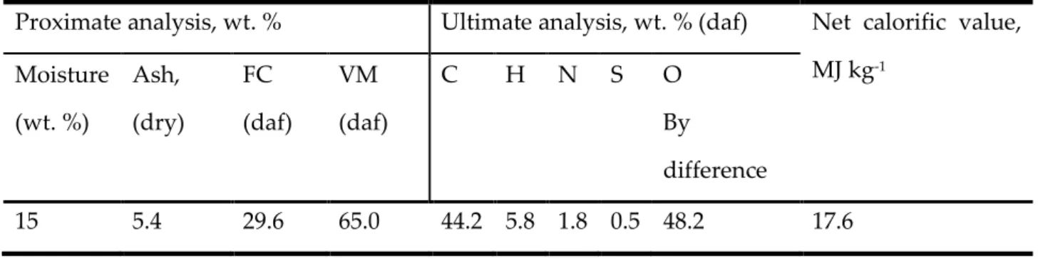
Table 2.3 Maximum allowable levels of impurities in syngas for chemical synthesis. Adapted from [27].
414 Impurity Specification H2S + COS + CS2 < 1 ppmv NH3 + HCN < 1 ppmv HCl + HBr + HF < 10 ppbv Na + K < 10 ppbv
Particles (soot, ash) “almost completely removed”
Tar Not condensing: below dew point
Hetero organic components (incl. S, N, O) < 1 ppmv 415
To achieve the stringent syngas quality requirements presented in ¡Error! No se encuentra
416
el origen de la referencia., primary mitigations, such as optimization of operational 417
conditions, catalytic bed materials or additives, combined with secondary hot gas cleaning
418
in the form of filtering of particulates, removal of impurities and catalytic cracking may be
419
needed [51].
Syngas conditioning
31
In this section the focus will be on secondary hot gas cleaning techniques i.e. downstream
421
of the gasifier, for particulate removal and tar mitigation. Figure 2.6 illustrate a simplified
422
schematic of the hot gas cleaning and conditioning process proposed by Kurkela et al. [54]
423
(Hot gas filtration route) and an innovative and promising but still not proven technology
424
proposed by Tuomi et al. [55] (High-T hot has filtration route) and studied by Pouya H.
425
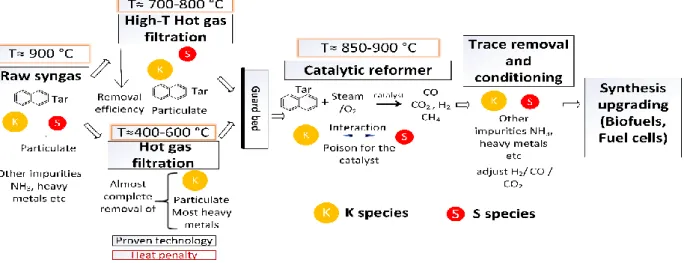
Moud [15]. 426
427
Figure 2.6 Simplified schematic of the hot gas cleaning and conditioning process for fuel cell and biofuels applications.
428
2.6.1 Hot gas filtration
429 430
Kurkela et al. [54] performed hot gas filtration experiments using a ceramic filter at 550 °C,
431
a temperature high enough to avoid tar condensation in the dust cake or inside the filter
432
pores which would lead to stickiness of dust and blocking of the filter pores. Higher
433
temperatures were found to result in a rapidly increasing filter pressure drop caused by the
434
thermal soot formation reactions of tars and ethene i.e. blinding effect, this effect was
435
amplified when the dust content was low, and the concentration of heavy tars was high [54].
436
Stable and unproblematic filter operation i.e. dust concentration below the detection limit
437
of 5 mg/m3n, was achieved throughout a 215-hour test run, during which the filter elements
438
were pulse cleaned at one hour intervals in order to remove dust cake from the candle filter
439
surfaces [54]. According to the authors [54] fine calcined dolomite particles appeared to
Introduction
32
protect the filter cake from sticky particles containing tar and soot. Moreover, potassium,
441
sodium and chorine species were completely removed in the hot filter unit.
442
Although, the economic benefits and process efficiency gain of elevating the filtration
443
temperature close to the gasifier temperature, around 800-900 °C have been acknowledged
444
the practical operation is challenging due to corrosion and material fatigue issues and only
445
few researcher have dealt with this topic [55], [56]. Simeone et al. [56] have performed
446
filtration tests at around 800 °C in steam-O2 gasification conditions with different bed
447
material (magnesite, olivine) and biomass feedstock (wood, miscanthus, straw)
448
combinations. From the authors [56] results it can be deduce that the selection of bed
449
material/fuel combination plays an important role in filter performance as they influence
450
the gas quality, especially tars, and dust load in the gas as well as the carry-over of bed
451
material to the filter. Complete removal of alkali species is hardly feasible, especially with
452
high alkali content feedstock [56]. Furthermore, contradictory results about the removal of
453
heavy tars and formation of light tars and naphthalene during high temperature filtration
454
hot gas filtration [55] expose the need for improvements in this field.
455
It is important to mention that the gradual build-up of the cake on the filter can have a
456
complex sorption effects that influence the levels of impurities reaching downstream units
457
[54]–[56].
458
2.6.2 The use of a guard bed before the catalytic reformer
459 460
The use of a guard bed before the catalytic reformer can increase the lifetime of the catalyst.
461
The most reactive and unstable species of the tar content in the raw syngas will removed or
462
converted to light (C1-2) hydrocarbons, H2, carbon oxides and more stable, usually aromatic
463
compounds with 1-3 rings e.g. benzene and naphthalene.
464
The use of low-cost materials as well as by-products of the gasification/pyrolysis process
465
will benefit the overall efficiency and profit of the biomass to biofuels or fuel cell technology.
466
In this regard, the use of char (biochar) derived from biomass pyrolysis/gasification as a tar
467
removal in a guard bed is considered a promising alternative [57]–[62]. Compared with
![Figure 2.5 Schematic of the proposed model for PAH formation during gasification. Adapted from [48].](https://thumb-eu.123doks.com/thumbv2/123dokorg/2894889.11525/29.892.88.793.115.563/figure-schematic-proposed-model-pah-formation-gasification-adapted.webp)
![Table 2.3 Maximum allowable levels of impurities in syngas for chemical synthesis. Adapted from [27]](https://thumb-eu.123doks.com/thumbv2/123dokorg/2894889.11525/30.892.105.762.645.924/table-maximum-allowable-levels-impurities-chemical-synthesis-adapted.webp)