2016 Publication Year
2020-07-03T09:26:43Z Acceptance in OA@INAF
Aligning the demonstration model of CHEOPS Title
BERGOMI, Maria; BIONDI, FEDERICO; MARAFATTO, Luca; DIMA, MARCO; GREGGIO, DAVIDE; et al.
Authors 10.1117/12.2232136 DOI http://hdl.handle.net/20.500.12386/26306 Handle PROCEEDINGS OF SPIE Series 9904 Number
Aligning the Demonstration Model of CHEOPS
M. Bergomi
*a, F. Biondi
a, L. Marafatto
a, M. Dima
a, D. Greggio
a,b, J. Farinato
a, D. Magrin
a,
R. Ragazzoni
a, V. Viotto
a, M. Gullieuszik
a, G. Farisato
a, L. Lessio
a, E. Portaluri
a, M. Munari
c,
I. Pagano
c, M. Marinai
d, A. Novi
d, C. Pompei
d, D. Piazza
e, T. Beck
e, V. Cessa
e, W. Benz
ea
INAF - Osservatorio Astronomico di Padova, Vicolo dell’Osservatorio 5, 35122 Padova, Italy
bDipartimento di Fisica ed Astronomia - Università degli Studi di Padova, Vicolo dell’Osservatorio
3, 35122 -Padova, Italy
c
INAF - Osservatorio Astrofisico di Catania, Via S.Sofia 78, 95123 Catania, Italy
dLeonardo Spa - Eo Payloads/ Propulsion Techn. & Assembly, Via A. Einstein 35, 50013-
Campi Bisenzio (Firenze), Italy
e Physikalisches Institut - Universität Bern, Sidlerstrasse 5, 3012 Bern, Switzerland
ABSTRACT
CHEOPS (CHaracterizing ExOPlanets Satellite) is an ESA Small Mission, planned to be launched in mid-2018 and whose main goal is the photometric precise characterization of radii of exoplanets orbiting bright stars (V<12) already known to host planets.
Given the fast-track nature of this mission, we developed a non-flying Demonstration Model, whose optics are flight representative and whose mechanics provides the same interfaces of the flight model, but is not thermally representative. In this paper, we describe CHEOPS Demonstration Model handling, integration, tests, alignment and characterization, emphasizing the verification of the uncertainties in the optical quality measurements introduced by the starlight simulator and the way the alignment and optical surfaces are measured.
Keywords: CHEOPS, exoplanets, transits, ESA, Small mission, telescope, AIV, prototyping
1. INTRODUCTION
CHEOPS (CHaracterizing ExOPlantes Satellite)[1][2] is a joint ESA-Switzerland Small Mission, adopted in 2014 and
planned to be launched in mid-2018. It will be sent into a low Earth (650-800 km) sun-synchronous orbit, with the main goal to perform, through the transit method, the precise characterization of radii of exoplanets orbiting bright stars (V<12) already known to host planets.
One of the main criticality in the development of such a system is the need to reach an extremely high photometric stability, driving its opto-mechanical design mainly in two fields: extreme structure stability and very high degree of straylight suppression. Details on the techniques developed to cope with this issue, along with the project status, can be found in [3], [4] and [5].
As for every space mission, the development of intermediate models is extremely important in order to decrease all possible risks. In particular, being CHEOPS a fast-track mission, it is of paramount importance to demonstrate the feasibility or criticalities of the AIV procedures, as well as the development of adequate Ground Support Equipment (GSE), ahead of their implementation on the Proto-Flight Model (PFM) by the Italian Prime contractor LEONARDO Spa (formerly SELEX ES), supervised by INAF.
For this reason, in collaboration with the University of Bern and LEONARDO, a Demonstration Model (DM) of CHEOPS telescope was developed. It consists in a non-flying CHEOPS model, whose mechanics is fully representative concerning interfaces but not thermally equivalent, and whose optics exhibits optical quality and handling capabilities very close to the flight model, allowing to test procedures for handling, integration, alignment and characterization.
Space Telescopes and Instrumentation 2016: Optical, Infrared, and Millimeter Wave, edited by Howard A. MacEwen, Giovanni G. Fazio, Makenzie Lystrup, Proc. of SPIE Vol. 9904,
990439 · © 2016 SPIE · CCC code: 0277-786X/16/$18 · doi: 10.1117/12.2232136 Proc. of SPIE Vol. 9904 990439-1
HO Internal affle M2 F 1 D2 I BE
1
M3 'upil stop - OBA In this paper, the CHEOPS uncertainties optical surfac Different mo Thermal Mod only for the structure: a c Back-End Op PSF over a q intermediate foreseen to ob Table 1. Table 1. M In Figure 1 it • an opto-m (M2) mirr • an Optica • the BEO, from the t focus the Figure 1 , we describe S DM was ass in the optica ces are measur2
dels were fore del, an Engin telescope, th compact on-ax ptics (BEO), r quite large am pupil mask fo btain very hig
Main parameter Ce is shown a C mechanical Tu rors al Bench Assem consisting of tube, a pupil m PSF onto the . CAD section v
the main step sembled, align l quality mea red. 2. CHEOP eseen to thoro eering Qualif he so-called T xis F/5 Ritche reshaping a de mount of pixe for the straylig gh photometry rs of the optical Spectral Entrance pup entral obstruct Workin Field of View Effective foc Pixel s Plate sc AD view of th ube, consisting mbly (OBA) f a mechanical mask, a foldin detector. view of TEL D ps and results ned and tested asurements int PS TELESC oughly test th fication Mode TEL subsyste ey-Chrétien tw efocused PSF els to average ght rejection y stability. Th configuration. range il diameter tion diameter g F/# (diameter) cal length size cale he TEL DM s g of a mechan l part mountin g mirror (M3) M. Main comp of the work p d in ambient troduced by th COPE DEMO e system, eve el, a DM, and m. It is com wo mirrors ce F on the detect e for single-pi and a baffle w e main param tructure, mad nical structure ng a set of sma ) to direct the
onents are indic
performed at temperature, he starlight si ONSTRATI en in a schedu d, finally, the mposed by two entered telesc tor [6]. The lat
ixels anomalie with vanes pr meters of the fi 400 – 3 6 8.38 0.32 2681 m 13 1 ar e by the assem mounting the all optics, a do light toward t
cated (blue mec
the laboratori with emphasi imulator and ION MODE ule as tight as PFM. The DM o optical syst ope, with an tter is due to es (see also [ receding the t inal optical co – 1100 nm 20 mm 68 mm @ 750 nm 2 degrees mm @ 750 nm 3 micron csec/pixel mbly of: e hyperbolic p oublet (D1), c the detector an
chanics, red opt
ies of INAF P is on the verif the way the a
EL
CHEOPS on M model has tems and the
aperture of 3 the choice of [7]). This, tog telescope, are onfiguration ar primary (M1) a collimating the nd a second d tics). Padova, where fication of the alignment and e: a Structura been realized eir mechanica 320 mm and a f spreading the gether with an e the solutions re collected in and secondary e light coming doublet (D2) to e e d al d al a e n s n y g o
Proc. of SPIE Vol. 9904 990439-2
rube +spider M1G + mainipulator OBA+ NWT supports manipi ube E M2G + ulator suppor The DM mec as the final o LEONARDO of light-weigh groups and m Figure 2 partial lig
The main req OBA referen reference for The foreseen alignment: fir Tube (current In this view, centering and aligned with requirements BEO wrt to T optical eleme should be ± 5 In order to f realization of summarized: 1. Alignm the bear material chanical struct one. The DM O and subcontr hting of M1. mechanics and . On top are D ght-weighting c quirement on nce frame (OB
centering is g n alignment p rstly, the Tub tly on-going a the overall re d focus and ± respect to M on internal a Tube tolerance ent inside BE 5 µm from Foc
fulfill the pre f specifics Op ment reference ring mechani lizing the opti
ture has been M optical group ractors, differ Both DM opt it is injected a DM mechanics can be observed 3. R
the TEL align BA side facin given by the pi procedure stra e (M1-M2) is activity). equirement ha 300 µrad in ti 1 with a prec alignment are es are translat EO with auton cal Plane). 4. eviously give ptical and Me e definition ical axis is a ical axis of the
realized by U ps (optics and ring from fligh tics and mech
after alignmen components, w d). REFERENC nment is that ng M1) with a ins were M1/t ategy, whose s aligned with s been split b ilt is required. cision of ± 5 mainly trans ted into ± 10 nomous adjus ALIGNME n requiremen echanical GSE aligned (cente e system. University of B d their mecha ht optics for n hanics are show
nt is complete
while on the bot
CES AND R the optical ax a precision of tube supports preliminary v h respect to the etween differe . Furthermore µm in centeri slated into me µm in focus, stment capabi ENT PROCE nts, the follow Es (see Figure er and tilt) to Bern in anodiz anics) have b not being radia wn in Figure ed. ttom DM mirro REQUIREM xis shall be al f ± 500 µm i are connected version was d e OBA; afterw ent componen , to guarantee ing and focus echanical tole ± 30 µm in c lity is D2 in EDURE & G wing integrati e 3 and Figur o the mechan zed aluminum een manufact ation-hardened 2. Glue acts a
ors held by the
MENTS ligned with re in centering a d. described in wards BEO is nts: on M1 an e the needed o s and ± 26 µm erances we wi entering and ± focus directi GSES
ion and align re 4), were de nical referenc m rather than i tured in flight d, the coatings as interface b eir alignment to espect to (wrt and ± 400 µra [6], consists s aligned with n alignment of optical quality, m in tilt. Con ill not detail, ± 600 µrad in ion (its alignm
nment strategy etermined and
ces on the OB
n carbon fiber t materials by s and the leve
etween mirror ools (on M1G a hereafter) the ad in tilt. The in a two-step respect to the f ± 100 µm in , M2 has to be ncerning BEO while overal n tilt. The only
ment accuracy y, along with d are hereafter BA, therefore r y el r a e e p e n e O, ll y y h r e
Proc. of SPIE Vol. 9904 990439-3
MGSEs:
- handling, used to support TEL DM into a vertical configuration;
- a bearing (wobble ∼60 μrad), equipped with a small optical bench and a centering and tilt adjustment system, located on the handling base-plate;
- a “ring”, connected to the OBA centering reference pins (0.02 mm precision wrt nominal mechanical reference);
- a column, equipped with dial gauges (2 µm accuracy) fixed onto the bearing, allows to touch the inner part of the ring and its bottom side, and, minimizing the value measured during a 360° rotation, to align the bearing to the reference plane.
2. M1 alignment to the OBA reference plane
M1 MGSE: a manipulator (visible in Figure 2 bottom left), equipped with three flexible blades supporting M1 (through specific channels present on each M1 bush). It is provided with two micrometers (0.1 µm sensitivity) for decenter and three micrometers (1 µm sensitivity) for tilt, corresponding to 0.75”. The tilt micrometers can provide also focus adjustment if shifted simultaneously by the same amount. The manipulator is installed onto a cart (orange in Figure 3), to be inserted under the OBA.
• M1 centering alignment is obtained mechanically aligning M1 to the bearing mechanical axis, with the same concept used for the reference alignment, minimizing the value measured by a dial gauge touching the inner hole of M1during a 360° rotation.
MGSEs: same as phase 1 (no ring).
• M1 tilt alignment is obtained minimizing a spot trajectory produced during a 360° rotation by a laser integral to the bearing.
GSE: a laser shining toward M1 and a camera recording the spot trajectory during a bearing rotation (both are integral to the bearing).
• M1 focus is adjusted mechanically to nominal values.
The previous three steps are of course iterated until reaching values inside requirements. 3. M1 gluing
After the alignment is obtained and its stability verified, M1 can be glued to its support injecting bi-component glue Hysol 9493 and letting it cure for approximately a week. Afterwards the manipulator can be removed.
4. Preliminary operations for M2 alignment
The requirement on M2 specified in Section 3 was translated into the minimization of tilt, power and coma Zernike coefficients below 0.05 λ in an interferometric double-pass alignment.
M2 OGSE: Zygo FlashPhase GPI interferometer (λ=632.8 nm) and a 330 mm collimated beam (COLL, obtained aligning an F/1.5 spherical element and a 330 mm Off-Axis Parabola, OAP).
• M1 optical axis materialization, through a flat mirror aligned to the bearing with an autocollimator.
GSEs: a 100 mm diameter flat mirror (FM1) installed over the OBA, facing down, equipped with tip-tilt adjustments; an autocollimator; the bearing assembly.
• TEL focal plane materialization, through a spherical gauge aligned to the bearing with a setup similar to the one used for M1 tilt alignment.
GSEs: a 25 mm diameter spherical mirror with radius of curvature 100 mm (SM1), equipped with x-y-z stages allowing to center it wrt M1 (minimizing a spot trajectory produced during a 360° rotation by a laser integral to the bearing) and adjust it in focus to the nominal position.
• Collimated beam alignment to the optical axis, thanks to a large flat mirror 45°-oriented located just over the bearing (Figure 3, left).
GSE: a 480 mm diameter λ/57 rms flat mirror (FM2), equipped with tip-tilt adjustment. 5. M2 alignment to M1
M2 is aligned wrt M1 in tilt, focus and center minimizing the Tilt, Power and Coma Zernike coefficients retrieved by the interferometer M2.
M2 MGSE: M1 manipulator can be slightly modified, inserting a spider-shaped support to hold M2 (visible in Figure 2, bottom right).
Proc. of SPIE Vol. 9904 990439-4
6. M2 glui After th Hysol 9 the man 7. Align B A strate Coordin minimiz GSEs: s Shims a Figure 3 stage and and M2 ready for large fla kinemati
Figure 4 a referen ing he alignment i 9493, while m nipulator is rem BEO with resp egy similar to nate Measurin zing interferom spherical gaug are used to adj
. CAD views o d then the full T alignment; the r M1 alignment at mirror 45°-or c repositionable
. Actual laborat nce flat mirror u
is obtained an monitoring the moved. pect to the Tu o M2 alignme ng Machine o metric Zernike ge located on t ust BEO tilt.
of the optical be TEL; the manip
bearing assem t. Right: setup f riented. On top e plate.
tory setup at IN used for its align
nd stability ve interferometr ube (M1-M2) ent is foreseen onto the focal e coefficients. the focal plan
ench for CHEO ulator cart (ora mbly (gray) can for M2 alignme p of the OBA
NAF-Padova for nment). Right: o
erified, M2 ca ric pattern and )
n, with a sph l plane and t .
ne, BEO mani
OPS DM AIV. T ange) can be par
be seen on the ent, an incomin are installed F r the DM AIV. overall setup du an be glued to d letting it cur herical gauge the BEO adju pulator with c The handling is rtially modified e handling base ng 330-mm coll FM1 (yellow)
Left: the setup uring M2 alignm o its support in re for approxi mechanically usted in tilt, centering, focu
s the red structu d to accommoda e-plate. Left: se imated beam is and SM1 (pin to obtain the 3 ment phase. njecting bi-co imately a wee y positioned b focus, center us and rotatio
ure holding the ate manipulator etup for bearing s directed towar nk), the latter i 330 mm collima omponent glue ek. Afterwards by means of a and rotation on capabilities e OBA in a firs r (green) for M1 g alignment and rd the TEL by a installed onto a
ated beam (with
e s a n, s. st 1 d a a h
Proc. of SPIE Vol. 9904 990439-5
5. ALIGNMENT RESULTS
The DM TEL AIV activity comprises two tube alignments campaigns. During the first one, a few issues were identified and addressed, but a poor quality in the tube/M1 support surfaces coupling translated in a very large astigmatism (estimated in more than 5 λ Peak to Valley, PtV) that would not allow to fully test the AIV procedure. The alignment was repeated after a very precise machining of the two surfaces, when a planarity lower than 10 μm was obtained, and implementing some of the lessons learned from the first run.
The main results of the second campaign will hereafter be summarized, focusing on the setup optical quality characterization and analysis of M1-M2 alignment, including its dependence on temperature and M2 rotation. We remind that BEO integration and alignment are currently on going.
5.1 M1 alignment
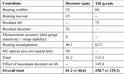
Following the procedure and the tools described in Section 4 (bullets 1 and 2), M1 was aligned in tilt, center and focus with respect to the reference plane defined on the OBA. Leaving aside the technicalities of the several steps leading to this alignment, Table 2 summarizes the main effects contributing to M1 alignment budget, summed in quadrature. An unavoidable contribute is given by the bearing wobble and runout, affecting also its alignment wrt OBA and therefore the reference for M1 alignment. In addition to these values, we have to include the machining precision of M1 hole with respect to its optical axis and to consider the effect of M1 decenter onto M1 tilt. The latter, in fact, while adjusted, tries to compensate the decenter, leading to a tilt misalignment. To be conservative we can sum linearly this contribution to the previous one, obtaining a total M1 tilt of approximately 258.7 (± 129.3) μrad - corresponding to approximately 53.6 (± 26.8)”- still below the 400 μrad of tolerance.
Table 2. Error contributions to M1 alignment wrt OBA.
Contribute Decenter (µm) Tilt (μrad)
Bearing wobble 35 60
Bearing run-out 15 --
Residual tilt -- 73
Residual decenter 32 --
Measurement accuracy (dial gauge
sensitivity + setup stability) 4 --
Bearing misalignment 40.1 62.5
M1 optical axis wrt central hole 50 --
Total 81.2 113.3
Effect of maximum decenter on tilt. -- 145.4
Overall total 81.2 (± 40.6) 258.7 (± 129.3)
5.2 Setup optical elements and DM mirrors characterization
Before proceeding to M2 alignment through double-pass interferometric measurements, we characterized our starlight simulator, along with the other setup mirrors, in order to minimize their impact on the overall alignment result. All measurements are expressed in wavelength (λ=632.8 nm) and the wavefronts (obtained from an average of 100 measurements) are shown in Figure 5.
In order to reduce the aberration on the collimator, its optics were aligned using the double-pass interferometric setup visible in Figure 4, which included also a 400-mm diameter reference flat whose optical quality is λ/10. The Zygo interferometer with its reference sphere was equipped with x-y-tip-tilt-rotation micrometric adjustments, while the OAP had previously be roughly aligned inside its own mount to have the optical axis almost parallel to the optical bench. Looking at the double pass interferograms, the main aberrations were minimized. To further reduce the aberrations produced by stress on the optics, OAP and reference mirror mount holders were properly tuned. The final result is 0.32 PtV, 0.07 rms, and the largest residual aberration is the spherical one, of the order of 0.1 λ.
Proc. of SPIE Vol. 9904 990439-6
1.0 p
:OLLD ii
M2a
COLL+FNr---1
1
First alignmE]C
M1 2nt 0.15 -0.1 Secornd alignment Afterwards, t flat mirror w previous one The other crit the one with the very satisFigure 5 the large Furthermore, was reported measured wh Figure 6 5.3 M2 al As first thing M2 held by it In this phase, PtV of 1.8 λ. second alignm (thanks to an Figure 7 tube). Rig visible fr to determine th was held horiz (0.43 PtV, 0.0 tical optical c the lower abe fying value of . Wavefronts (o 45°oriented fla to have a qua d to us by LE hile laying on i . DM M1 and M lignment g, to understan ts manipulator , after M2 alig . The analysis ment, M1 was imperfection . Left: M1 glue ght: wavefront rom an imperfec he effect of F zontally on th 09 rms), with omponent to b errations. The f 0.1 PtV, 0.08 obtained by the at mirror and th alitative and q EONARDO an its rear-side an M2 wavefronts, nd the impact r but without i gnment was p s to understan s rotated of 12 in M1 grindin d to OBA and M s obtained in th ction in M1 itse M2, the collim hree points a a distinguisha be tested was latter was the 8 rms. e average of 10 he spherical gau quantitative ide nd the wavefr nd before the provided by LE of the tube o installing the erformed, we nd its origin id 20° and so doe ng - noticeable M2 located on his configuratio elf, marked by a mated beam r above FM2. T able trefoil ma SM1, the sph en tested insid 00) of the main uge. ea of the aberr fronts are show
bushes were g
EONARDO.
n the primary tube (see Figu noticed a dom dentified M1 a es the astigma e also in Figur manipulator du on during first a a dashed line.
eached the lar The overall o ainly due to th herical gauge. de its own mo optical elemen rations introdu wn in Figure glued to the m y mirror aberr ure 7). minant astigm as the main re atism. This is c re 6 - that has
uring the first ph and second align
rge 45°-orient obtained resul he reference m We tested di ount, which w nts used during uced by DM m 6. It is impo mirror. ations, we per matism of the o esponsible. In clearly visible been marked hase of M2 alig nment of the tu
ted mirror and t is slightly l mirror holding fferent mirror was modified u M2 alignment, mirrors, their o ortant to note rformed the a order of 0.7 λ n fact, between e in the wavef d by a dashed l gnment (perform ube. M1 was ro d the reference larger wrt the . rs and selected until obtaining , the collimator optical quality e that M1 was alignment with λ on an overal
n the first and fronts Figure 7
line).
med without the tated, as clearly e e d g r, y s h ll d 7 e y
Proc. of SPIE Vol. 9904 990439-7
-8:8z
-0.11 LL -ó'38 Be m=-( 24.3 ÿ 0.060 0.055 m_0 0.050 0.94'3 7 0.53 t 0.49 0.45 24.3 m: 0.026 7 0.024 - m 0.022-.7. 0.020 -0.018 24.3 ÿ 0.05 A 0.04 Eo 0.03 m=-I u 0.0Z. `.0.685 m-0 0.680 -' 0.675 AC á 0.670 24.3 7 2.12 2.10 -E 2.08-2.0§24.3 0.36 - =0.35-0 =0.35- 034Ê 0.33 -0.32 24.3 efore M2 gluinl 0.800 24.6 Temp [°C] 1.009 24.6 Temp [ °C] =0.135 ' 24.6 Temp [ °C] i=0.005-cr
24.6 Temp ["C]0.030 L
24.6 Temp [°C] 1.015 24.6 Temp ["C] 24.6 Temp [°C] 24.6 Temp 1°C] NJ LO LO Tilt [A] Tref[A1 Spher[A] Focus[A]J,2j
rtns [A] PtV [a] Astig [a] 000OW After8:2-_2-
'z- m=-037 8:4 24.7 0.07 0.06 - m=0.03 8.84-0.03 0.02 ' 24.7 0.68 m=0.09 0.62 - ...7....04-o..= 0.60 0.58 24,7 0.07 Ó.Ó5 -8.83 - m =4.03 0.02 ' 24.7 880 - m=00 075 070 88824.7 o 2.30 2.25 2.20 2.15 2.10 m=0.02 24.7 24.7 0.37 ¡ 0.36 0.35 0.34 0.33 24.7 M2 gluing 25.1 Temp 1°C1 25.1 Temp [ °C] 25.1 Temp 1°C] 25.1 Temp 1 °C] 25.1 Temp 1°C] 25.1 Temp [ °C] 25.1 Temp [ °C] 25.1 2 Temp [°C] When the tu coefficients v variation can dependence o direction to th of zerodur an Since our lab of all the mai however be a which increas before and af Figure 8 complete on the m considerube was insta varying the m nnot be expli on temperatur he three M1 a nd invar, with oratory showe in Zernike coe adjusted with t ses at the incr fter M2 gluing
8. Variation of ed (right). Befor mismatch betwe
the sum in qua
alled, variatio ost were the s icitly determin
re, which was attachment po respect to OB ed a variation efficients from the manipulat rease of tempe g are reported f main Zernike re gluing, tilt, p een M1G zerod adrature of the tw ns of the ord spherical coef ned, even th s not monitor ints, we infer BA, realized in in temperatur m the temperat tor (of course erature. The re
in Figure 8.
’s coefficients power and coma dur and invar w wo coefficients
der of 0.2 Pt fficient, which ough the ord red during thi that this effec n aluminum.
re of a few de ture. The main
before gluing elationships b with temperat a can be compe with respect to O s. tV were obse h decreased b der of magnit is operation. ct is mainly d egrees during t n dependence g M2 to the sp between the m
ture during alig ensated with ma OBA aluminum erved on the y about 0.05 tude is 0.1 λ Given the co due to the mism
the AIV phase e is of course t pider). The sec main Zernike c
gnment phase anipulator, whil m. For tilt, com
wavefront. T λ and the tref λ, since it sh orrespondence match betwee e, we tested th the focus term cond most evi coefficients an
(left) and afte le trefoil is prob ma, astigmatism
The Zernike’s foil. The latter hows a strong of the trefoi en M1G, made he dependence m, which could ident is trefoil nd temperature r M2 gluing i bably dependen m and trefoil, we s r g il e e d l, e s nt e
Proc. of SPIE Vol. 9904 990439-8
Til Corr 0.9 0.8 0.7 0.6 0.5 0.4 30 t 0.04: Pow -( la 0.01; Spher * patism til o o
IIIIiiiiIi,
60 90 M2 rotatior ).01; Ast 0.67; r 0.05; Tref 0.: 0 0 120 150 ' 1 [1 36 Pist, Ast,Tilt, Pow, Cor
Spher remov Another aspe Figure 6 they on the manip for temperatu for astigmatis aberration, w Figure 9 astigmati astigmati A typical inte 10, left. In Fi aberration, w Figure 1 23.8°C (w and the w
The last step hours) M2 co of 0.075 λ) a temperature c curing, the m are shown in A picture of Figure 11 righ ect that we in y are the two d pulator), M2 w ure modulatin sm over 180° e selected M2 9. Dependence ism shows a mi ism was selecte
erferogram an igure 10, righ here trefoil is 0. From left to we remind the wavefront after of M2 AIV w ould still be re and a variation corresponding manipulator wa Figure 8 right the telescope ht. nvestigated wa dominant aber was aligned w g all of them and a minimu 2 rotation angl of astigmatis inimum every ed. nd wavefront, ht, it is shown clearly distin o right: a repre dependence of removing main
was its gluing, e-aligned to M n in the sphe g to the mome as removed an t column. taken after co as the influen rrations on M wrt to M1 and at T=24.3°C um for trefoil le correspondi sm and trefoil 180°, while tre taken at T= 2 n also the wav nguishable. esentative interf f the Zernike co n aberrations, w with Hysol 9 M1, the operati erical aberratio ent in which th nd new wave ompleting the nce of M2 rot M2. After each 50 wavefront (with the rela l over 120° w ing to the min
on M2 rotati foil every 120° 23.8°C, after M vefront after r ferogram obtai oefficients on te where the trefoil
9493 (Figure 1 ion introduced on. Furthermo he glue gets su fronts were ta e tube integrat tation on astig h rotation (ope ts were averag ationship show was observed. nimum of the a
ion, with valu °. To reduce the M2 alignment emoving tilt, ned averaging emperature); its l is clearly visib 11). Even thou d coma aberra ore, the minim ufficiently stif aken. The obt tion, alignmen
gmatism and eration assiste
ged. After cor wn in Figure Given the dom astigmatism. es corrected f e total PtV, the t was complet power, coma 50 after M2 a s relative wave ble.
ugh during the ation above th mization of th ff (about 3 hou tained results, nt and verific trefoil, since d by a goniom rrecting the ob 8, as expected minance of th for temperature orientation of
ted, are presen , astigmatism alignment, with efront (PtV is 1 e first curing p he requiremen he power is o urs after gluin
dependent on ation wrt OBA , as visible in meter installed btained values d, a minimum he astigmatism e. As foreseen M2 minimizing nted in Figure and spherica h temperature a .8 λ; rms 0.3 λ phase (about 2 nt (of the order obtained at the ng). After glue n temperature A is shown in n d s m m n, g e al at λ) 2 r e e e, n
Proc. of SPIE Vol. 9904 990439-9
Figure 11 Left: glue injection to fix M2 to the spider. Right: OBA and tube assembled and aligned.
6. CONCLUSIONS
TEL DM alignment, integration and verification of the Tube (M1-M2) have been successfully completed at INAF-Padova laboratories. The main outcomes of this activity are a few lessons-learned, which translated into new strategies elaborated by LEONARDO for PFM, both in the definition of GSEs, in the glue injection and the alignment strategy itself. Furthermore, hands-on experience, along with tip and tricks discovered along the way can certainly help to speed up the alignment process of the PFM, which is supposed to start in a few weeks. Next steps on DM side include BEO optics integration to its mechanics and BEO alignment to the tube. A few TEL DM optical quality verification are also foreseen: an interferometric double-pass test and the measure of the defocused PSF radius (defined as 90% of Encircled Energy) over the entire Field of View.
7. AKNOWLEDGMENTS
CHEOPS activities in Italy are supported by the Italian Space Agency (ASI) - Agreement ASI-INAF n. 2013-016-R.0 09/07/2013.
REFERENCES
[1] Broeg, C., Fortier, A., Ehrenreich, D., Alibert, Y., Baumjohann, W., Benz, W., Deleuil, M., Gillon, M., Ivanov, A., Liseau, R., Meyer, M., Oloffson, G., Pagano, I., Piotto, G., Pollacco, D., Queloz, D., Ragazzoni, R., Renotte, E., Steller, M., Thomas N. and the CHEOPS team, “CHEOPS: A Transit Photometry Mission for ESA’s Small Mission”, EPJ Web of Conferences 47, 03005 (2013)
[2] Fortier, A., Wehmeier U.J., Benz W., Broeg C., Cessa V., Ehrenreich D., Thomas N., “CHEOPS: a Space Telescope for Ultra-high Precision Photometry of Exoplanet Transits”, Proc. SPIE 9143, 91432J (2014) [3] Rando, N., Asquier, J., Corral Van Damme, C., Isaak, K., Ratti, F., Safa, F., Southworth, R., Broeg, C., Benz,
W., “ESA CHEOPS mission: development status”, SPIE Proc. This conference (2016)
[4] Beck, T., Fortier,A. Broeg, C., Malvasio, L., Cessa, V., Piazza, D., Benz, W., Thomas, N., Magrin, D., Viotto, V., Bergomi, M, Ragazzoni, R., Pagano, I., Peter, G., Buder, Plesseria, J-Y D., Steller, M., Ottensamer, R., Ehrenreich, D. , Corral, C., Isaak, K., Ratti, F., Rando, N., Ngan, I., “CHEOPS: status summary of the instrument development” SPIE Proc. This conference (2016)
[5] Blecha, L., Zindel, D., Cottard, H., Beck, T., Cessa, V., Broeg, C., Ratti, F., Rando, N. “Analytical optimization and test validation of the submicron dimensional stability of the CHEOPS space telescope's CFRP structure”, SPIE Proc. This conference (2016)
[6] Bergomi, M., Viotto, V., Magrin, D., Dima, M., Greggio, D., Farinato, J., Marafatto, L., Ragazzoni, R., Munari, M., Pagano, I., Scandariato, G., Scuderi, S., Beck, T., Buxton, R., Piazza, D., Benz, W., Broeg, C., Cessa, V., Piotto, G., “AIV procedure for a CHEOPS demonstration model”, SPIE Proc., 9143, 91435B (2014)
Proc. of SPIE Vol. 9904 990439-10
[7] Magrin, D., Farinato, J., Umbriaco, G., Kumar Radhakrishnan Santhakumari, K., Bergomi, M., Dima, M., Greggio, D., Marafatto, L., Ragazzoni, R., Viotto, V., Munari, M., Pagano, I., Scandariato, G., Scuderi, S., Piotto, G.; Beck, T.; Benz, W.; Broeg, C.; Cessa, V.; Fortier, A.; Piazza, D., “Shaping the PSF to nearly top-hat profile: CHEOPS laboratory results”, SPIE Proc., 9143, 91434L (2014)
Proc. of SPIE Vol. 9904 990439-11