2D IR spectroscopy with phase-locked
pulse pairs from a birefringent delay line
Julien R´ehault,1Margherita Maiuri,1Cristian Manzoni,1Daniele Brida,2Jan Helbing,3and Giulio Cerullo1,∗
1IFN-CNR, Dipartimento di Fisica, Politecnico di Milano, Piazza Leonardo da Vinci 32,
20133 Milano, Italy
2Department of Physics and Center for Applied Photonics, University of Konstanz, D-78457
Konstanz, Germany
3Department of Chemistry, University of Z¨urich, Winterthurerstrasse 190, 8057, Z¨urich,
Switzerland *[email protected]
Abstract: We introduce a new scheme for two-dimensional IR spec-troscopy in the partially collinear pump-probe geometry. Translating bire-fringent wedges allow generating phase-locked pump pulses with excep-tional phase stability, in a simple and compact setup. A He-Ne tracking scheme permits to scan continuously the acquisition time. For a proof-of-principle demonstration we use lithium niobate, which allows operation up to 5 μm. Exploiting the inherent perpendicular polarizations of the two pump pulses, we also demonstrate signal enhancement and scattering sup-pression.
OCIS codes: (320.7160) Ultrafast technology; (300.6530) Spectroscopy, ultrafast; (300.6300) Spectroscopy, Fourier transforms; (300.6340) Spectroscopy, infrared.
References and links
1. P. Hamm, M. Lim, and R. M. Hochstrasser, “Structure of the amide I band of peptides measured by femtosecond nonlinear-infrared spectroscopy,” J. Phys. Chem. B 102, 6123–6138 (1998).
2. P. Hamm and M. T. Zanni, Concepts and Methods of 2D Infrared Spectroscopy (Cambridge University, 2011). 3. M. Cho, Two-Dimensional Optical Spectroscopy (CRC Press, 2009).
4. G. D. Goodno, G. Dadusc, and R. J. D. Miller, “Ultrafast heterodyne-detected transient-grating spectroscopy using diffractive optics,” J. Opt. Soc. Am. B 15, 1791–1794 (1998).
5. M. C. Asplund, M. T. Zanni, and R. M. Hochstrasser, “Two-dimensional infrared spectroscopy of peptides by phase-controlled femtosecond vibrational photon echoes,” Proc. Natl. Acad. Sci. U.S.A. 97, 8219–8224 (2000). 6. S.-H. Shim, D. B. Strasfeld, E. C. Fulmer, and M. T. Zanni, “Femtosecond pulse shaping directly in the mid-IR
using acousto-optic modulation,” Opt. Lett. 31, 838–840 (2006).
7. L. P. DeFlores, R. A. Nicodemus, and A. Tokmakoff, “Two-dimensional Fourier transform spectroscopy in the pump-probe geometry,” Opt. Lett. 32, 2966 (2007).
8. U. Selig, F. Langhojer, F. Dimler, T. Lhrig, C. Schwarz, B. Gieseking, and T. Brixner, “Inherently phase-stable coherent two-dimensional spectroscopy using only conventional optics,” Opt. Lett. 33, 2851–2853 (2008). 9. J. Helbing and P. Hamm, “Compact implementation of Fourier transform two-dimensional IR spectroscopy
with-out phase ambiguity,” J. Opt. Soc. Am. B 28, 171–178 (2011).
10. V. Cervetto, J. Helbing, J. Bredenbeck, and P. Hamm, “Double-resonance versus pulsed Fourier transform two-dimensional infrared spectroscopy: An experimental and theoretical comparison,” J. Chem. Phys. 121, 5935– 5942 (2004).
11. E. H. G. Backus, S. Garrett-Roe, and P. Hamm, “Phasing problem of heterodyne-detected two-dimensional in-frared spectroscopy,” Opt. Lett. 33, 2665–2667 (2008).
12. W. Xiong and M. T. Zanni, “Signal enhancement and background cancellation in collinear two-dimensional spectroscopies,” Opt. Lett. 33, 1371–1373 (2008).
13. J. R´ehault and J. Helbing, “Angle determination and scattering suppression in polarization-enhanced two-dimensional infrared spectroscopy in the pump-probe geometry,” Opt. Express 20, 21665–21677 (2012).
14. J. R´ehault and J. Helbing, “Exploring the polarization degrees of freedom in collinear two-dimensional infrared spectroscopy,” EPJ Web of Conferences 41, 05003 (2013).
15. S.-H. Shim and M. T. Zanni, “How to turn your pump-probe instrument into a multidimensional spectrometer: 2D IR and vis spectroscopies via pulse shaping,” Phys. Chem. Chem. Phys. 11, 748–761 (2009).
16. D. R. Skoff, J. E. Laaser, S. S. Mukherjee, C. T. Middleton, and M. T. Zanni, “Simplified and economical 2D IR spectrometer design using a dual acousto-optic modulator,” Chem. Phys. 422, 8–15 (2013).
17. D. Brida, C. Manzoni, and G. Cerullo, “Phase-locked pulses for two-dimensional spectroscopy by a birefringent delay line,” Opt. Lett. 37, 3027–3029 (2012).
18. M. T. Zanni, N.-H. Ge, Y. S. Kim, and R. M. Hochstrasser, “Two-dimensional IR spectroscopy can be designed to eliminate the diagonal peaks and expose only the crosspeaks needed for structure determination,” Proc. Natl. Acad. Sci. USA 98, 11265–11270 (2001).
19. J. R´ehault, V. Zanirato, M. Olivucci, and J. Helbing, “Linear dichroism amplification: Adapting a long-known technique for ultrasensitive femtosecond IR spectroscopy,” J. Chem. Phys. 134, 124516–124516–10 (2011). 20. D. N. Nikogosyan, Nonlinear Optical Crystals: A Complete Survey (Springer, 2005).
21. D. E. Zelmon, D. L. Small, and D. Jundt, “Infrared corrected Sellmeier coefficients for congruently grown lithium niobate and 5 mol.% magnesium oxide-doped lithium niobate,” J. Opt. Soc. Am. B 14, 3319–3322 (1997). 22. N. Demird¨oven, M. Khalil, O. Golonzka and A. Tokmakoff, “Dispersion compensation with optical materials for
compression of intense sub-100-fs mid-infrared pulses” Opt. Lett. 27, 433 (2002).
23. C. T. Middleton, A. M. Woys, S. S. Mukherjee, and M. T. Zanni, “Residue-specific structural kinetics of proteins through the union of isotope labeling, mid-IR pulse shaping, and coherent 2D IR spectroscopy,” Methods 52, 12–22 (2010).
24. S. T. Roberts, J. J. Loparo, K. Ramasesha, and A. Tokmakoff, “A fast-scanning Fourier transform 2D IR interfer-ometer,” Opt. Commun. 284, 1062–1066 (2011).
25. K. F. Lee, A. Bonvalet, P. Nuernberger, and M. Joffre, “Unobtrusive interferometer tracking by pathlength oscil-lation for multidimensionalspectroscopy,” Opt. Express 17, 12379–12384 (2009).
26. M. Downs and K. Raine, “An unmodulated bi-directional fringe-counting interferometer system for measuring displacement,” Precision Engineering 1, 85–88 (1979).
27. L. Lepetit, G. Ch´eriaux, and M. Joffre, “Linear techniques of phase measurement by femtosecond spectral inter-ferometry for applications in spectroscopy,” J. Opt. Soc. Am. B 12, 2467–2474 (1995).
28. U. Schlarb and K. Betzler, “Refractive indices of lithium niobate as a function of wavelength and composition,” J. Appl. Phys. 73, 3472–3476 (1993).
29. R. Bloem, S. Garrett-Roe, H. Strzalka, P. Hamm, and P. Donaldson, “Enhancing signal detection and completely eliminating scattering using quasi-phase-cycling in 2D IR experiments,” Opt. Express 18, 27067–27078 (2010). 30. F. Perakis and P. Hamm, “Two-dimensional infrared spectroscopy of supercooled water,” J. Phys. Chem. B 115,
5289–5293 (2011).
31. T. Steinel, J. B. Asbury, J. Zheng, and M. D. Fayer, “Watching hydrogen bonds break: a transient absorption study of water,” J. Phys. Chem. A 108, 10957–10964 (2004).
32. R. Maksimenka, P. Nuernberger, K. F. Lee, A. Bonvalet, J. Milkiewicz, C. Barta, M. Klima, T. Oksenhendler, P. Tournois, D. Kaplan, and M. Joffre, “Direct mid-infrared femtosecond pulse shaping with a calomel acousto-optic programmable dispersive filter,” Opt. Lett. 35, 3565–3567 (2010).
33. S. P. Davis, M. C. Abrams, and J. W. Brault, Fourier Transform Spectrometry (Academic Press, 2001). 34. K. Ataka, T. Kottke, and J. Heberle, “Thinner, smaller, faster: IR techniques to probe the functionality of
biolog-ical and biomimetic systems,” Angew. Chem. 49, 5416-5424 (2010).
35. H. Rhee, Y.-G. June, J.-S. Lee, K.-K. Lee, J.-H. Ha, Z. H. Kim, S.-J. Jeon, and M. Cho, “Femtosecond charac-terization of vibrational optical activity of chiral molecules,” Nature 458, 310–313 (2009).
1. Introduction
Since its first demonstration by Hamm et al. [1], two-dimensional infrared spectroscopy (2D IR) has developed as an important technique to describe molecular structure, measure cou-plings between vibrational modes of a molecule and track structural dynamics on the picosec-ond timescale [2, 3]. While 2D IR was first realized in the frequency domain [1], time domain techniques are usually preferred [4–9], as they have better spectral resolution in the pump fre-quency axis, and because they maintain the time resolution afforded by the spectral bandwidth of the laser pulses [10]. The two schemes most widely used for time-domain 2D IR are the heterodyne detected three-pulse photon-echo and the partially collinear pump-probe geometry. The heterodyne photon-echo configuration is the most versatile and sensitive but also the most complex way of performing 2D spectroscopy. It requires the overlap of four independent beams at the sample, two pumps, one probe and one heterodyning pulse, and interferometric
stabilization of the pulses in pairs, the two pumps and the probe with the heterodyning pulse. The phase between the two pump beams is scanned and must be determined accurately at the sample [11] for proper recovery of the line-shape. This configuration allows to record, by inverting the ordering of the two pump pulses, the so-called rephasing and non-rephasing spectra. They can provide some additional insight into the origin of cross and diagonal peaks, but high spectral resolution is best afforded by their sum, the absorptive spectrum. An additional advantage of the photon echo configuration is the independent control of the intensity and polarization of the four pulses.
In comparison, the partially collinear configuration leads naturally to absorptive lineshapes, requires that only two beams (one for the two pump pulses and one for the probe) be over-lapped on the sample and allows a straightforward determination of the relative delay of the collinear pump pulses [7, 9]. The probe beam has the dual purpose of generating the nonlin-ear polarization and heterodyning the signal (self-heterodyning), as the signal is emitted in the probe direction. For these reasons, this configuration is in principle less flexible and sensitive than the heterodyne photon-echo, but control of the polarization and intensity of the four fields interactions is still possible by the use of polarizers in both the pump and probe beams [12–14]. If we compare it to standard pump-probe spectroscopy, the additional requirement of 2D spectroscopy is to resolve the frequency of the pump pulses. This can be done in the time domain by scanning the delay t1between two pump pulses and Fourier transforming the probe data along t1 to finally obtain the additional frequency axis of the 2D spectra. The accurate control or determination of delay t1, or coherence time, within a fraction of the optical cycle is the key to obtain properly phased 2D spectra, and this is the main technical hurdle of 2D spectroscopy in the time domain. Current implementations of collinear 2D IR spectroscopy make use of a pulse shaper [15, 16] or an interferometer [7, 9]. When using a pulse shaper, the phase and delay t1between the two pulses are fully controlled, and can be changed on a pulse to pulse basis, allowing fast and efficient scanning of t1. However, pulse shapers in the mid-IR are expensive and significantly increase the complexity of the experimental setup. With an interferometer, t1can be scanned continuously and determined precisely by monitoring the fringes of an auxiliary visible beam collinear with the IR one.
We recently introduced a novel optical configuration, called TWINS (Translating-Wedge-Based Identical Pulses eNcoding System) which solves in a simple, compact and cost-effective way the problem of building a collinear delay line with interferometric stability. This device exploits the birefringence of an optical material to impose an arbitrary delay on two orthogonal polarization components by continuously varying the material thickness. TWINS has already been successfully implemented in the visible range using as birefringent materialβ-barium bo-rate and demonstbo-rated excellent phase stability (better thanλ/360) and reproducibility for 2D electronic spectroscopy. Here, we extend the TWINS concept to 2D IR spectroscopy, using as birefringent material lithium niobate, whose transparency extends out to 5 micron. We imple-mented a He-Ne tracking scheme very similar to the one used by Helbing et Hamm [9], that allows to scan t1continuously and record a full 2D spectrum in less than 30 s.
Besides its compactness and simplicity, advantage of the TWINS configuration is that it naturally produces a pair of perpendicularly polarized pump pulses. They can be projected to the same polarization with an additional polarizer for conventional 2D spectroscopy [17]. However, it is also possible to use the two perpendicularly polarized pulses to remove scattering and enhance signal with the use of polarizers in the probe beam [13, 14, 18, 19].
2. Measurement principle
When a light beam propagates in a birefringent material, it experiences a refractive index that depends on its polarization. The orientation of the optical axis with respect to the light
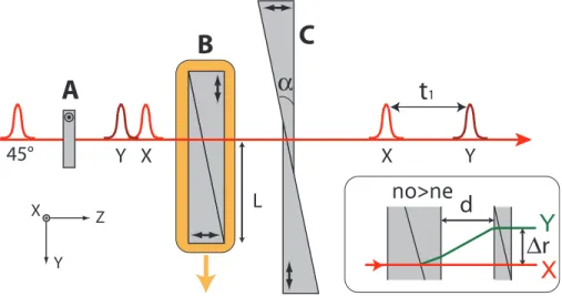
propaga-tion direcpropaga-tion determines two main polarizapropaga-tion axes, the ordinary and the extraordinary axis. As a consequence, the group velocity of a pulse propagating in such materials depends on its polarization. This effect can be used to generate two orthogonally polarised pulse replicas, and to finely tune their relative delay by adjusting the material thickness. The pulses generated this way are also intrinsically phased-locked, as they propagate along the same path. This effect is employed in the TWINS device [17], schematically shown in Fig. 1. Let us first consider block B, consisting of two wedges with optical axis rotated by 90◦. Upon transverse displacement of this block, light polarized in X direction is not affected, as it propagates in the two wedges with the same ordinary index of refraction, and thus experiences a constant optical path. In contrast, the light polarized in the Y direction propagates with ordinary index of refraction in the first wedge, and with the extraordinary index in the second wedge. In a negative birefringence ma-terial (no>ne), the X polarized pulses is delayed relative to the Y polarized pulses, depending on the position of the moving wedge pair.
Z Y X
α
t
145°
Y X
X
Y
A
B
C
L
X
Y
d
Δ
r
no>ne
Fig. 1. Principle of the TWINS. Block A introduces a constant negative delay. Block B moves to scan t1. Block C corrects the parallelism and front tilt of the beams. Arrows indicate the orientation of the optical axis in each element. Below each pulse is indicated its polarization. Inset : Path for X and Y-polarized beams inside the TWINS. Angles are exaggerated for clarity.
As shown in the inset of Fig. 1, the perpendicularly polarized beams created by a single pair of wedges are not exactly parallel, they suffer from spatial chirp, and the phase front of the extraordinary beam is slightly tilted. This is corrected by the second pair of static wedges, after which the two beams are now parallel and almost collinear. The insertion of the second wedge pair into the beam is kept as small as possible to minimize dispersion. When both prism pairs are in contact, the X-polarized pulse is not displaced. In contrast, the Y polarization is refracted at every interface. It is again parallel to the X-polarized pulse but it is displaced by an amountΔr depending on the first wedge pair insertion L (proportional to t1), the distance between the two wedge pairs d, the apex angle of the wedgesα and the birefringence of the material. When d=10 mm and L=0 mm (t1=0 ps), the calculated beam displacement isΔr=105
μm. Every additional delay of 1 ps, corresponding to a translation L of 3.2 cm, increasesΔr by
50μm. Here, we could neglect the influence of the lateral displacementΔr of the Y polarization
relative to the X polarization, as the beam size (8mm) is significantly bigger than the maximal displacement (170μm overall). In the case of smaller beam, for longer scans or for materials with higher birefringence, this effect should be carefully taken into account as it could lower
the signal size at long t1delays. This effect could distort the lineshapes, or affect the balance between rephasing and non-rephasing contributions. In fact, the phase-matching direction of the signal will be affected at long t1and not be any more collinear with the probe. A solution to this problem could be to reflect back the beams into the TWINS, which would produce a perfectly collinear pair of pulses while doubling the delay t1.
Since the wedge system can introduce only positive delay between X and Y, we used an additional birefringent plate with the extraordinary axis oriented along the X axis (Block A in Fig. 1); this plate introduces a negative delay between X and Y, allowing to access zero time delay during the scan of the moving wedges. A half-wave plate placed before the wedge sequence tunes the balance between the X- and Y-polarized pulse intensity.
Our goal is to use the TWINS device to generate phase-locked pulse pairs in the mid-IR spectral range. Table 1 reports a list of candidate birefringent materials which are transpar-ent in the mid-IR [20]. Magnesium fluoride could be considered, as it is standard material for waveplates in the mid-IR, but it has a too small birefringence for our application. Silver gal-lium sulfide (AgGaS2) and selenide (AgGaSe2) are commonly used as non-linear material, they have a good mid-IR transparency, but their relatively small birefringence require to build big wedges (on the order of 10 cm). Thallium based crystal (Tl4HgI6and Tl3AsSe3) have interest-ing properties but are still exotic and difficult to grow in large sizes, they also do not transmit visible light, preventing alignment of the wedges with a visible laser beam. The most favourable material, in terms of both transparency and birefringence, is Hg2Cl2(calomel). However this material is not readily available and, for a proof of concept, we have selected LiNbO3, which has a transparency window extending up to 5.2 μm, a reasonably high birefringence and is commercially available in the size requested for our experiment.
Table 1. Characteristics of a selection of birefringent materials at 4μm [20]. GVM: group velocity mismatch between ordinary and extraordinary polarizations.
Material Ordinary index Birefringence (ne-no) GVM (fs/mm) Range (μm)
LiNbO3 2.1142 -0,0583 310 0.4-5.2 Hg2Cl2 1.8976 0.549 1847 0.4-20 CdGeAs2 3.5431 0.096 423 2.4-11.5 AgGaS2 2.4027 -0.05368 177 0.58-10.6 AgGaSe2 2.6787 -0.0326 105 0.58-10.6 MgF2 1.34883 0.0099 45 0.2-7 LiO3 1.8163 -0.109 578 0.5-5 Tl4HgI6 2.3914 0.0688 230 1.0-60 Tl3AsSe3 3.3651 -0.187 639 2-12
LiNbO3has a negative birefringence (ne−no) of the order of 5.8 10−2around 4μm, meaning that a wedge thickness of 6 mm results in a phase delay between the two pump pulses of 1.16 ps. Based on the Sellmeier coefficients of LiNbO3 [21], the group delay is of 1.86 ps. The relatively small birefringence of LiNbO3 requires the use of rather large wedges to produce the delay necessary for sufficient spectral resolution along the pump axis of a 2D IR spectrum. With an angle of 10◦, the wedge needs to be longer than 3.2 cm for a group delay of 1.86 ps, which becomes 4 cm if we account for our beam diameter of 8 mm. Block A has a thickness of 1.5 mm, and the overall thickness of the TWINS is≈9 mm. The total group delay dispersion (GDD) introduced by the TWINS is approx -15000 fs2, and over compensate the estimated 4000 fs2 of the pulses coming out the infrared optical parametric amplifier. Still, the pump pulses
have a duration below 200 fs. The residual GDD could be compensated by a propagation in a germanium plate with 11 mm thickness [22]. The wedges are anti-reflection coated. The overall transmission of the TWINS device with the polarizers is better than 50% for each polarization. To move the wedges, we used a motor (M-112.2DG Physik Instrumente) with a resolution of 0.1μm, which corresponds to a t1resolution of approximately 56 attoseconds at 5μm given the wedge angles and their birefringence at this wavelength. The accuracy in positioning is then better thanλ/300.
A polarizer at 45◦can be used after the device to project the X and Y-polarized pulses onto a common plane of polarization. To this aim, we use a wire-grid polarizer, which also separates the polarizations into a reflected and a transmitted one. The reflected polarization is used to monitor and record the interference between the two pump pulses during the measurement (see Section 3 and Fig. 2). The transmitted polarization is sent to the sample and overlapped spatially with the probe beam. As already mentioned, for polarization sensitive 2D spectroscopy this polarizer can be removed.(see Section 4).
3. Continuous scanning with He-Ne delay tracking
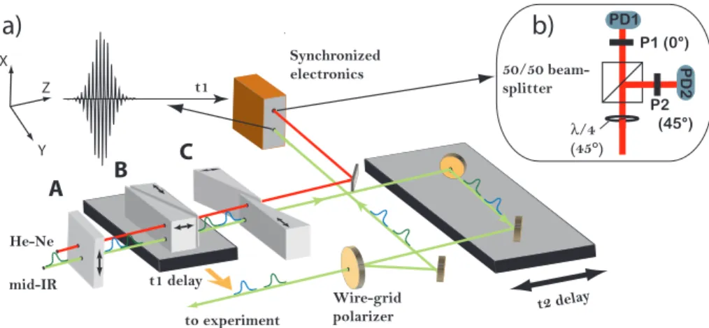
To perform fast and accurate 2D IR experiments, it has been demonstrated that continuous scanning reduces the acquisition time while improving signal-to-noise ratio [9, 23, 24]. When the motor is scanned fast and continuously during data acquisition, however, the internal motor control can hardly follow its position at the kHz repetition rate of the measurement. For this reason, delay tracking with a HeNe laser is often used [9,25]. Its implementation in the TWINS setup is particularly straightforward and illustrated in Fig. 2.
Z Y X
A
B
C
He-Ne mid-IR to experiment Wire-grid polarizer t2 dela y t1 delay 50/50 beam-splitter P1 (0°) P2 (45°) PD1 PD2 λ/4 (45°) Synchronized electronicsa)
b)
t1Fig. 2. (a) Wedge sequence and pump beam propagation through the wedges. The He-Ne beam co-propagates with the mid-IR beam, through blocks A, B and C (Fig. 1).The wire-grid polarizer is set at 45◦relative to X and Y, the polarized reflected part is sent to the electronics to detect the interference between the two pump pulses which is used to phase the data. This polarizer is removed when perpendicular pump pulses are used (see Section 4) (b) He-Ne tracking schemes.
A He-Ne beam passes through the wedges with an input polarization at 45◦relative to the optical axis. Then, a quarter-wave plate is oriented at 45◦relative to the X and Y axes before a 50/50 beamsplitter. In each of the two splitted beams, a polarizer projects the polarization along X and at 45◦respectively. The two interference signals measured by the photodiode are in quadrature and allow to track the motor position without ambiguity of the direction of the movement. This scheme is illustrated in Fig. 2(b).
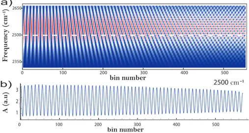
During the scan, we binned in time the probe data by referring the motor position to the He-Ne interferences [9, 26, 27], which allows to accumulate data on a regular time grid. Using the He-Ne cycle as the reference for the delay step corresponding to one bin, each mid-IR cycle was sampled with about 7 time points. This number is conditioned by the different birefringence of the wedge material in the mid-IR and at 632nm. To verify this, we first scanned the delay be-tween the two pump pulses at 4μm (2500 cm−1), and detected their spectral interferences with an infrared spectrometer, on a 32-pixel array detector. The resulting spectrogram is shown in Fig. 3(a). The number of He-Ne bins filled during the full scan is 570, corresponding to a phase delay of 1200 fs at 632.8 nm. At infrared frequencies, where the birefringence is smaller, it corresponds to a phase delay of approximately 835 fs, consistent with the 62 fringes observed at 2500 cm−1in Fig. 3(b). This corresponds well to the expected delay of 855 fs, deduced from the motor range (25 mm), the angle of the wedges (10◦) and using the Sellmeier coefficients of LiNbO3[28]. This map is also used to calibrate the pump axis of the 2D IR spectra [17, 27]. In addition, this scan exhibits excellent repeatability, confirming the reliability of the wedge-based scheme. Note that the time domain interferometry does not require high-resolution spectrome-ters, but high-accuracy delay control. This is clear if we explore the data of Fig. 3 at high bin numbers; the low resolution of the spectrometer undersamples the spectral interferences (panel (a)). However, a cut along the time axis at 2500 cm−1(panel (b)) can be highly sampled since it only depends on the accuracy of the delay line. The low spectral resolution affects the am-plitude of the oscillation at high bin numbers. Such amam-plitude modulation is negligible after Fourier transform. 200 300 400 500 2650 2500 2350 100 0 bin number F requenc y (cm ) -1
a)
b)
2500 cm-1 bin number A (a.u) 100 200 300 400 500 200 300 400 500 100 0 2 1 3Fig. 3. (a) Spectral interferometry of the two pump pulses in function of bin number, de-termined with the He-Ne quadrature detection scheme. (b) Cut of (a) (dashed line) at 2500 cm−1.
One advantage of TWINS is the high accuracy and reproducibility in setting the t1 delay even with low precision motors. Ideally the scan speed should enable sampling of the signal at Nyquist frequency, in order to take best advantage of the noise correlation during a full scan [9]. Given the gear ratio of the wedges, this would correspond to a speed of 60 mm/s, which was not accessible with our motor. The motor used here to move the wedge pair has a full range of 25 mm, that can be scanned at the maximum speed of 2 mm/s. With the current speed, we are in a regime of slow scanning rate, and, given the 1 kHz repetition rate of the laser, we accumulate about 40 shots per He-Ne cycle at the maximum speed of the motor. At this speed of 2 mm/s,
a single scan of a full 2D spectra with a resolution better than 10 cm−1(about 1.8 ps delay) is possible in less than 30 s, but averaging of successive scans might be necessary when low signals are measured.
The counting scheme developed here can also provide information about the accuracy and linearity of the motor displacement. One scan consists of forward and back translation of the motor over the available 25 mm range. By monitoring the number of pulses per He-Ne bin, we observed that the velocity is perfectly linear after acceleration and before deceleration (which take about 500 ms or 500 shots here). Also, this data was repeated thirty times and led to the exactly same results. Because the pump pulses are phase-locked, the phase fluctuations can be neglected.
This suggests that the high gear ratio ensures a reproducible equidistant time grid even during fast scanning which should thus be possible without fringe counting, or other forms of delay tracking based on pump-pulse interference [7]. Without the auxiliary He-Ne beam the setup could become even simpler. However, delay tracking avoids timing errors that may still arise from software synchronization or electronic drift. The fringe contrast of the visible He-Ne beam also provides excellent feedback for optimizing the wedge alignment.
The case of faster scans at the Nyquist frequency was not studied as the motor could not reach the required speed of 60 mm/s. This capability can be studied more easily in the visible range, where the shorter wavelength and higher birefringence allow to reach the Nyquist rate with smaller velocities. We noticed that continuous scanning was still beneficial even at low speed, but faster scan rate are desirable to make best use of the intensity correlation between successive laser shots.
In pump-probe experiments the pump beam is usually blocked periodically with an optical chopper in order to normalize the signal and to eliminate slow intensity fluctuations of the probe beam. In 2D IR measurements in the pump-probe geometry selective chopping of only the static pump beam can also eliminate background signals due to scattered pump light [7]. Since selective chopping is not possible in the TWINS configuration, in order to reject scattering, we use here an alternative scheme of fast pump-probe delay modulation [9]. A window wobbling at one quarter of the laser repetition rate introduces a periodic delay to the pump beam [29]. The signals recorded at delay shifts of−2π/ω, 0, 2π/ω, 0, . . . can be averaged so that scattering contributions are suppressed by more than two orders of magnitude in the spectral window of interest. Delay modulation was not necessary for the polarization measurements described in Section 4, as the scattering is naturally suppressed in this configuration.
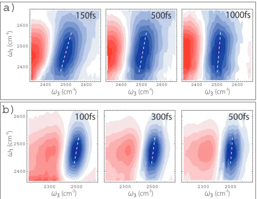
To demonstrate the capability of the TWINS setup we show in Fig. 4(a) set of 2D IR spectra of a solution of 5% of HOD in H2O for different values of the population time t2. The OD stretch vibration gives rise to an intense and inhomogeneously broadened absorption band near 2500 cm−1. We observe a positive signal due to the 0-1 transition (bleach and stimulated emis-sion, blue) and, at lower frequencies, a negative signal due to the 1-2 transition (photoinduced absorption, red). The tilt of the 2D IR signal is a measure of the correlation between pump and probe vibrational frequencies. Consistent with the literature [30,31], this correlation is lost on a picosecond timescale, and this dynamics can be related to the fluctuations of the hydrogen bond network of water. The small tilt observed here can be explained by the low temporal resolution of the set-up (≈ 200 fs).
4. Polarization measurements
Without polarizer in the pump-beam the TWINS setup delivers a pair of pump pulses with very well-defined perpendicular polarizations. These pulses can be used directly for 2D spectroscopy with improved signal to noise when placing an additional polarizer into the probe beam behind the sample [12–14, 19]. The polarizer extinguishes the probe beam almost completely and the
150fs
500fs
1000fs
2600 2400 2500 2600 2400 2500 2400 2500 2600 2400 2500 2600ω₁
(cm-¹)ω₃
(cm-¹)ω₃
(cm-¹)ω₃
(cm-¹) 2300 2500100fs
300fs
500fs
2300 2500 2300 2500 2600 2400 2500ω₃
(cm-¹)ω₃
(cm-¹)ω₃
(cm-¹)ω₁
(cm-¹)a)
b)
Fig. 4. Set of 2D IR spectra of the OD stretch of 5% HOD in H2O for population times (t2) specified in the upper right corner of each spectrum. (a) All parallel measurement (XXXX) (b) Polarization measurements (YXXY). Spectral diffusion, which is revealed by the tilt of the bleaching signals highlighted by the white dotted line, decays in the sub-picosecond time scale.
portion leaking through it acts as a local oscillator, amplifying the nonlinear signal. The pos-sible polarizations of the four fields (given by the two pump pulses, the probe pulse and the signal/local oscillator) in the 2D experiment are then either YXYX or XYYX.
Scattering signals are suppressed in the YXYX scheme as the probe polarizer (X) acts as a filter to remove all the scattered light coming from the first pump pulse (polarization Y). Scattered light from the second static pump pulse (polarization X) is present on the detector, but it is completely eliminated by the Fourier transform because its interference with the probe pulse remains unchanged as a function of t1. The probe pulse at the sample can also be made very intense without saturating the detector. Hence, as long as the signal is anisotropic, it can be enhanced significantly [13, 14]. The spectra obtained this way are shown in Fig. 4(b). The XYYX scheme can be also easily measured by placing a half-wave plate in the pump beam after the TWINS, to interchange the two pump pulse polarizations, but the scattering is not be suppressed in that case.
Fig. 4(b) shows the 2D IR measurement of the OD stretch spectrum with perpendicularly polarized pump pulses and a polarizer in the probe beam (polarizations XYXY). The probe beam at the sample could be made approximately 10 times stronger than in the experiment with all parallel polarizations shown in Fig. 4(a). As a result, the signal to noise ratio at short waiting times is much better. Since only the anisotropic signal is amplified, isotropic background due to heat is suppressed. However, the signal decays very quickly with the loss of anisotropy due to fast reorientation (≤ 1 ps) of the O-D transition dipole [31].
5. Discussion and conclusion
In this paper we have introduced a method for performing 2D IR spectroscopy based on a birefringent delay line. The TWINS apparatus is simple and compact and allows to generate phase-locked pulses with an extremely high phase stability. TWINS can be introduced easily in the pump beam of a pump-probe set-up, and is by far the simplest method to produce phase-locked pulse pairs with perpendicular polarization. It is therefore particularly well suited for anisotropy measurements and signal amplification using polarizers. This can also be exploited to determine angles between transition dipole moments with improved accuracy [13] and to eliminate diagonal peaks by subtracting signals recorded with polarization orders Y XY X and
XYY X [18]. The exceptional accuracy in setting the t1delay could also be exploited for accurate and fast undersampling of the t1-axis and improve speed of acquisition in the case of step scan acquisition.
The current limitations of the set-up are due to the small birefringence and limited spectral transmission of LiNbO3. An absorption due to free OH in the crystal prevented us from per-forming any measurement in the 3400 to 3600 cm−1spectral region. The actual transparency range (2000 cm−1 to 3400 cm−1) limits the usefulness of LiNbO3 to the measurements of stretch vibrational modes like OD, CD or C≡N, but does not allow to access the fingerprint region (500 to 1500 cm−1) and the amide bands (1600 cm−1) of peptides.
Candidate material with better characteristics are difficult to find for application of the TWINS in the IR. An excellent candidate material for applications of TWINS to the mid-IR appears to be crystalline mercurous chloride (Hg2Cl2) , also known as calomel. It has a very large birefringence (10 mm of calomel can introduce a path difference of 5 mm between or-thogonal polarizations, translating into a frequency resolution of 2 cm−1) and transmits IR light between 380 nm and 20μm. It was used recently as an infrared material for an acousto-optic programmable dispersive filter [32]. Yet, calomel is a difficult material to process in large sin-gle crystals and the cost of production currently prohibits its use for large optics. We are now developing strategies to be able to use smaller crystals and improve the throughput of the se-quence, which will permit to utilize calomel for 2D IR spectroscopy with birefringent wedges. The availability of calomel will enable application of the TWINS approach to other vibrational spectroscopy techniques, such as FTIR [33], step-scan FTIR [34] and time domain circular dichroism spectroscopy [35].
Acknowledgments
This work was supported by the European Research Council Advanced Grant STRATUS (ERC-2011-AdG No. 291198). JR and JH thank the Swiss National Science Foundation for financial support (Fellowship PBZHP2 143444 and Grant No.200020 129938 ).
![Table 1. Characteristics of a selection of birefringent materials at 4 μ m [20]. GVM: group velocity mismatch between ordinary and extraordinary polarizations.](https://thumb-eu.123doks.com/thumbv2/123dokorg/8263218.130127/5.918.196.727.612.798/characteristics-selection-birefringent-materials-velocity-mismatch-extraordinary-polarizations.webp)