Dipartimento di Ingegneria dell‘Energia Elettrica e
dell‘Informazione “Guglielmo Marconi”
Scuola di Dottorato in Automatica e Ricerca Operativa XXIX CICLO
Settore Concorsuale: Area 09/G1 Automatica Settore Scientifico Disciplinare: ING-INF/04 Automatica
Haptic Device Design and Teleoperation
Control Algorithms for Mobile
Manipulators
Coordinatore Dottorato: Prof. Daniele Vigo
Supervisore: Prof. Claudio Melchiorri Autore:
Alberto Pepe
Tesi conforme ai requisiti
per il rilascio del titolo di Doctor of Philosophy in
Automatica e Ricerca Operativa
I, Alberto Pepe, declare that this thesis titled, ’Haptic Device Design and Teleoperation Control Algorithms for Mobile Manipulators’ and the work presented in it are my own. I confirm that:
⌅ This work was done wholly or mainly while in candidature for a research degree at this University.
⌅ Where any part of this thesis has previously been submitted for a degree or any other qualification at this University or any other institution, this has been clearly stated.
⌅ Where I have consulted the published work of others, this is always clearly at-tributed.
⌅ Where I have quoted from the work of others, the source is always given. With the exception of such quotations, this thesis is entirely my own work.
⌅ I have acknowledged all main sources of help.
⌅ Where the thesis is based on work done by myself jointly with others, I have made clear exactly what was done by others and what I have contributed myself.
Signed:
Date:
i
Abstract
School of Engineering and Architecture
Department of Electrical, Electronic and Information Engineering (DEI) “Guglielmo Marconi”
Doctor of Philosophy
Haptic Device Design and Teleoperation Control Algorithms for Mobile Manipulators
by Alberto Pepe
The increasing need of teleoperated robotic systems implies more and more often to use, as slave devices, mobile platforms (terrestrial, aerial or underwater) with integrated manipulation capabilities, provided e.g. by robotic arms with proper grasping/manipu-lation tools. Despite this, the research activity in teleoperation of robotic systems has mainly focused on the control of either fixed-base manipulators or mobile robots, non considering the integration of these two types of systems in a single device. Such a com-bined robotic devices are usually referred to as mobile manipulators: systems composed by both a robotic manipulator and a mobile platform (on which the arm is mounted) whose purpose is to enlarge the manipulator’s workspace. The combination of a mo-bile platform and a serial manipulator creates redundancy: a particular point in the space can be reached by moving the manipulator, by moving the mobile platform, or by a combined motion of both. A synchronized motion of both devices need then to be addressed. Although specific haptic devices explicitly oriented to the control of mobile manipulators need to be designed, there are no commercial solution yet. For this reason it is often necessary to control such as combined systems with traditional haptic devices not specifically oriented to the control of mobile manipulators.
The research activity presented in this Ph.D. thesis focuses in the first place on the de-sign of a teleoperation control scheme which allows the simultaneous control of both the manipulator and the mobile platform by means of a single haptic device characterized by fixed base and an open kinematic chain. Secondly the design of a novel cable-drive haptic devices has been faced. Investigating the use of twisted strings actuation in force rendering is the most interesting challenge of the latter activity.
The first thanks goes to all the people I have shared the last years with. My supervisor, professor Claudio Melchiorri who gave me the chance to choose my way while kept on steering me in the right direction. He also gave me the great honor to be his teaching assistant in the course of Industrial Robotics. This 4 years activity turned out to be one of the most satisfying professional experiences of my life. A great thanks goes to Gianluca Palli for the everyday support and valuable advices, and for having routed my research activity to the haptic device design. Thanks to Luigi Biagiotti and Alessandro Macchelli for never having lost track of my progress. A great thanks to professor Eugenio Faldella for showing me that there is so much to learn even from co↵ee-breaks.
I would like to thank my fellow labmates with whom I share much more than the years of PhD: Umberto, Daniele, Lorenzo, Davide, Federico, Roberto, Riccardo and Mohssen. The great Caccia and the wise Christian. I truly thank my family: my parents, Cristina and Gian Marco, my brothers Michele and Francesco but also Eugenia, Betti, Laura Elisa for the unconditional support in everyday life.
Last but not least I sincerely would like to thank all the people that kept on pushing me also in the hard times of this long learning journey. Growing old is mandatory, growing up is optional.
Declaration of Authorship i
Abstract iii
Acknowledgements iv
Contents v
List of Figures viii
1 Introduction 1
1.1 Research goals . . . 1
1.2 Thesis structure . . . 2
2 Focus on Robotic Teleoperation 4 2.1 Introduction . . . 4 2.2 Brief history . . . 7 2.3 Range of application . . . 11 2.3.1 Telesurgery . . . 11 2.3.2 Underwater exploration . . . 12 2.3.3 Space exploration . . . 13 2.3.4 Other applications . . . 15 2.4 Haptic devices . . . 15
2.4.1 Serial kinematic structure . . . 17
2.4.2 Parallel kinematic structure . . . 18
2.5 Mobile manipulators . . . 19
2.5.1 KUKA youBot . . . 22
3 Design and Control Issues in Robotic Teleoperation 25 3.1 Degree of autonomy . . . 25 3.1.1 Direct control . . . 26 3.1.1.1 Position-position control . . . 27 3.1.1.2 Position-rate/acceleration control . . . 27 3.1.1.3 Comparison . . . 28 3.1.2 Shared control . . . 29 v
3.1.3 Supervisory control . . . 30
3.2 Master/Slave kinematics comparison . . . 31
3.2.1 Kinematically equivalent mechanisms . . . 31
3.2.2 Kinematically unequal mechanisms . . . 32
3.3 Motivation and related issues . . . 32
3.3.1 Mobile Manipulators teleoperation . . . 32
3.3.2 Haptic device design . . . 34
4 The Hybrid Teleoperation Control Scheme 37 4.1 Motivation . . . 37
4.2 The hybrid control algorithm . . . 38
4.2.1 Grasping Area . . . 40
4.2.2 Navigation Area . . . 40
4.2.3 Transition Area . . . 43
4.3 System description . . . 44
4.3.1 The master device . . . 44
4.3.2 The slave device . . . 45
4.3.3 Configuration switching and singularity issues . . . 46
4.4 Experimental results . . . 47
4.4.1 The grasping task . . . 48
4.4.2 Overall behavior through the three control regions . . . 49
4.4.3 Master/Slave position mapping in the transition area . . . 50
5 Design of the UBHaptic 52 5.1 Motivation . . . 52
5.2 Basic principles of TSA actuation . . . 53
5.3 System design . . . 54
5.4 Kinematic model of the haptic interface . . . 57
5.5 Device dimensioning . . . 60
5.5.1 Workspace sizing . . . 60
5.5.2 Actuation and transmission sizing . . . 62
5.6 The TSA module . . . 63
5.7 Real setup . . . 67
6 Design of the TSA Module 70 6.1 Motivation . . . 70
6.2 System description . . . 71
6.2.1 Force sensor . . . 72
6.2.2 Other components . . . 77
6.3 Control system architecture . . . 78
6.4 Experimental results . . . 82
6.4.1 Force sensor calibration . . . 83
6.4.2 Force control tests . . . 84
7 Conclusions and Future Works 87 7.1 Hybrid control scheme . . . 87
Bibliography 91 My Publications . . . 102
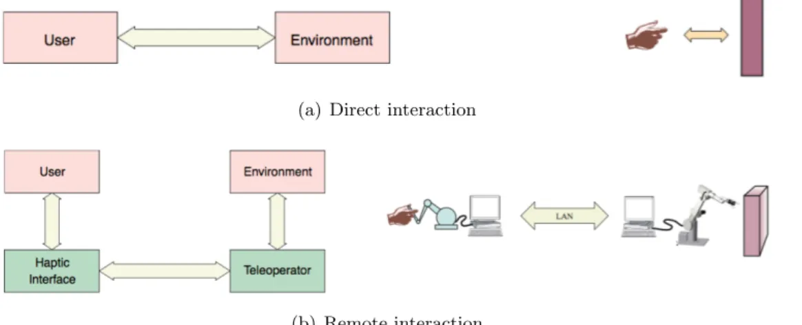
2.1 Direct interaction with a local environment and interaction with a remote environment by means of a telerobotic system. . . 5 2.2 Overview of a telerobotic system (from [1]). . . 5 2.3 Bilateral teleoperation system: the user controls the position Xm of the
master haptic device which is sent to the slave robot in terms of motion commands. The Interaction forces between the slave robot and the remote environment are transmitted back and displayed to the user as a haptic force F m (see [2]). . . 6 2.4 Raymond C. Goertz in the early 1950s handling radioactive material using
the first (mechanical) teleoperator. . . 8 2.5 The telerobotic system CRL Model M2 developed by the Oak Ridge
Na-tional Laboratory and used by NASA in deep space assembly applications (1982). . . 8 2.6 JPL ATOP control station (early 1980s). . . 9 2.7 ROTEX, the first remotely controlled robot in space (1993). Telerobot in
space and ground operator station. (Courtesy of the German Aerospace Center, DLR). . . 10 2.8 Operation Lindberg. The first transcontinental telerobotic surgery (2001). 10 2.9 The Da Vinci surgical system. . . 11 2.10 The remotely controlled Jason ROV (Fig. 2.10(a)) and the system of
television cameras and sonars Argo (Fig. 2.10(b)). Both were used to locate the Titanic in 1985. . . 13 2.11 ROKVISS, a space telerobotic system in which a ground operator by
means of stereo vision and haptic feedback controls a slave robot place in the proximity of the ISS (International Space Station). . . 14 2.12 The DLR telemanipulation system. . . 14 2.13 The Phantom Omni device by SensAble Technologies and the today’s
Geomagic Touch by 3D Systems. This low-cost device senses motion in six degrees of freedom and can apply forces in the x, y, and z directions to the stylus tip. . . 18 2.14 Novit Falcon: commercial parallel haptic interface addressing the game
industry but widely used in research. . . 19 2.15 Figure 2.15(a) shows a standard di↵erential drive mobile robot while
Fig-ure 2.15(b) shows the same robot equipped with manipulation capabilities. 20 2.16 Mobile robot with omnidirectional wheels. . . 21 2.17 The KUKA youBot mobile manipulator composed by a omni-directional
mobile platform Fig. 2.17(a) and a 5 DoF robotic manipulator Fig. 2.17(b). 23 2.18 Overview of the serial kinematic chain of the KUKA youBot arm. The
figure illustrates joints limits and links length. . . 24 viii
2.19 The KUKA youBot mobile manipulator available in single-arm
configu-ration Fig. 2.19(a) and dual-arm configuconfigu-ration Fig. 2.19(b). . . 24
3.1 Di↵erent types of control architectures for telerobotics system depending on the degree of autonomy of the slave robot. . . 26
3.2 Transfer function between master and slave in position and position-velocity control schemes. . . 29
3.3 An example of application of the shared control concept in telesurgery. . 30
4.1 Characterization of the master device’s workspace . . . 39
4.2 Mapping between the master and slave arm positions. . . 41
4.3 Velocity generation . . . 42
4.4 System used for the experimental evaluation. . . 44
4.5 The roll angle ↵ of the youBot end-e↵ector is defined according to the value of the last joint j6 of the PHANToM device while the pitch angle is related to the value of the fifth joint j5. . . 46
4.6 Inner-arm and outer-arm configurations . . . 46
4.7 Master and slave position tracking along x. . . 48
4.8 Master and slave position and mobile platform velocity through the three control regions. . . 49
4.9 Master and slave mapping across the transition area. From the left side: grasping, transition and navigation area. . . 50
5.1 (Top) Basic concept and (Bottom) schematic representation of the twisted string actuation system. . . 54
5.2 The 5-fingers DEXMART anthropomorphic hand based on TSA. . . 55
5.3 3D CAD rendering of the proposed haptic interface. . . 56
5.4 Di↵erent 3D views of the Human-Machine Interface. . . 56
5.5 Schematic view of the haptic interface and actuators arrangement. . . 57
5.6 Kinematics of the haptic interface. . . 58
5.7 2D and 3D views of the available workspace of the haptic interface. . . 61
5.8 Sampling of the workspace surface SR1. . . 62
5.9 Result of the sizing simulation . . . 64
5.10 Result of the simulation with respect to the strings lengths. . . 65
5.11 Schematic representation of the TSA structure. . . 65
5.12 Design detail of the first version of the TSA module. . . 66
5.13 Scheme of the sensor structure and component arrangement. . . 66
5.14 Detailed view of the TSA module prototype and control electronics. . . . 67
5.15 Prototype of the bracelet-like HMI based on gimbal mechanism. . . 68
5.16 Arrangment of the workspace frame and the mobile frame on the haptic device by means of Vicon markes. . . 68
5.17 Workspace frame and Mobile frame captured by the Vicon system. . . 69
6.1 Parallel and series connection of Belleville springs. . . 72
6.2 Main design parameters of a Belleville spring. . . 73
6.3 Design and characteristics of the light fork KRB011 (from manufacturer datasheet). . . 74
6.4 The available Belleville springs produced by Igus: external diameter De, internal diameter Di, thickness t, maximum deformation h0, 25% of the maximum deformation S0.25, force at 25% of maximum deformation F0.25, 50% of maximum deformation S0.5, force at 50% of maximum deforma-tion F0.5, 75% of maximum deformation S0.75, force at 75% of maximum
deformation F0.75, force at maximum deformation F1, weight M . . . 75
6.5 CAD design of the force sensor. . . 76
6.6 Section view of the TSA module and the integrated optoelectronic force sensor. . . 77
6.7 CAD design of the motor module and real prototype. . . 78
6.8 The TSA controller. . . 79
6.9 Interconnection between the TSA module, the embedded controller and the development workstation. . . 79
6.10 System controller architecture. . . 80
6.11 Structure of the UDP control packets sent from the workstation. . . 82
6.12 Schematic view of the experimental setup. . . 83
6.13 Calibration data acquired from the sensor (black squares) and correspond-ing polynomial interpolatcorrespond-ing curve (red). . . 84
6.14 Tracking of a force set-point of 30 N when sinusoidal disturbances of dif-ferent frequencies are applied on the twisted string. On top, force mea-surements are given highlighting the e↵ect of the force feedback, while at the bottom the position profile of the linear motor is shown. . . 85
Introduction
1.1
Research goals
Teleoperation systems have been the first discipline to come to light in the scene of robotics research back in the 40s. Since then, although the research in au-tonomous robots has made great strides making robots more and more intelligent and able to execute even very complex tasks without the need of human supervi-sion, a costant growth of applications involving robots teleoperation has still been recorded. Main reasons can be found in the native perception capabilities and decision making skills of the human being that cannot be left aside when dealing with operations in remote and unstructured environments.
Teleoperated robots permit the interaction with environments that are dangerous or of difficult access, e.g. space or underwater exploration, or with a di↵erent scale with respect to the typical human perspective, as for example in the case of microsurgery [3].
Control problems arises when a the master and the slave robots of a telerobotic system present kinematically dissimilar mechanical structures as the case of the slave robot is a mobile manipulators. A mobile manipulator represent the inte-gration of traditional n-DoF (Degrees of Freedom) fixed-base robotic arm and a standard (nonholonomic or omnidirectional) mobile robot in a single robotic de-vice. Such a integration increases the manipulator’s working range potentially to infinite, but also introduces redundancy, which means that there exist an infi-nite set of solutions in the joint space of both the arm and the mobile base, for a given end-e↵ector configuration. A properly combined motion of both devices needs then to be addressed. Although specific haptic devices explicitly oriented to the control of mobile manipulators need to be designed, there are no commercial
solution yet. For this reason traditional fixed-base haptic devices not specifically oriented to the control of mobile manipulators and in general with a lower number of DoF need to be used.
The hybrid control algorithm for a standard mobile manipulator presented in Chapter 4 tries to overcome the kinematic mishmach between the master and the slave robots providing an intuitive interface to the operator who controls the 8 DoF of the slave robot by means of fixed-base 6 DoF haptic interface.
For a more detailed discussion on the issues related to mobile manipulators tele-operation that have motivated this research please refer to Section 3.3.1.
The second part of the activity has focused on the design of a novel cable-driven haptic inteface addressed to teleoperate generic robotic devices. Many researchers have shown that the availability of haptic interfaces able provide the operator with sufficient kinesthetic information about the interaction forces exchanged between the slave robot and the remote environment can considerably improve the perfor-mance of the teleoperation task.
The ideal haptic inteface is supposed to have low inertia, low friction, low torque ripple, backdrivability, and low backlash in the actuation and transmission sys-tems. Besides this, many applications requests considerable workspace of the master device in order to properly mimic the slave characteristics. Commercial (sensibly expensive) solutions do not guarantee all these features, which in general are in contrast between each others.
Cable transmission may be promising candidates to solve these limitations because it minimizes the actuators contribution to the haptic’s end-point inertia and en-cumbrance, providing a considerable force-weight ratio.
Despite many solution of haptic interface embedding cable trasmission have been proposed in literature, there seems to be a gap in the investigation of Twisted String Actuation (TSA) in haptic force-rendering.
More details on the issues related to the topic that have motivated the design of the UBHaptic see Section 3.3.2.
1.2
Thesis structure
The thesis is organized as follow:
• In Chapter 2 a bref introduction to robots teleoperation systems is presented. In particular a general overview of the main features and components of a
telerobotic system as well as brief hystorical perspective and main applica-tions is provided. A particular focus has been reserved to the classification of haptic devices and to the introduction of mobile manipulators;
• In Chapter 3 the main issues related telerobotics are introduced. In particular Sec. 3.3.1 and 3.3.2 focus on the issues that have motivated the definition of the hybrid control algorithm for a generic mobile manipulator and the design of the UBHaptic respectevely;
• In Chapter 4 the hybrid control algorithm is presented and discussed as well as the the experimental setup used to validate the proposed approach. Experimental results are provided at the end of the chapter;
• In Chapter 5 the design of the haptic interface based on TSA is presented. First the overall structure is discussed and the inverse and di↵erential kine-matic models are introduced. A description of the criteria and the simulation results used for the workspace dimensioning and actuation/trasmission sizing is then provided as well as a preliminary design of the TSA module;
• In Chapter 6 the design of the new TSA module is discussed with a particular focus on the design of the integrated optoelectronic force sensor. The problem of the integration between the di↵erent system’s components is also addressed and the structure of control system architecture is described. Experimental results are proposed and discussed at the end of the chapter;
• In Chapter 7 the results of the research are summarized drawing guidelines for further developments;
Focus on Robotic Teleoperation
2.1
Introduction
Robots teleoperation (i.e. telerobotics) is perhaps the earliest field of application of robotics. Literally meaning doing work at a distance [4], it is generally used to refer to robotic systems with a human operator in control or human-in-the-loop [1]. Any high-level, planning, or cognitive decisions are made by the human user, while the robot is responsible for their physical/mechanical implementation (see Fig. 2.1). In essence, the brain is removed or distant from the body. The inclusion of the human operator makes telerobotics very attractive to handle unknown and unstructured environments.
The term tele, which is derived from the Greek and means distant, implies the idea to have a human operator controlling a robot operating in a remote location as shown in Fig. 2.2.
Besides distance, barriers may be imposed by hazardous environments or scaling to very large or small environments. All barriers have in common that the user cannot (or will not) physically reach the environment.
From a functional point of view a teleoperation system can be divided in two main parts: the local site with the human operator and all the hardware needed to im-plement a physical connection with him/her (e.g joysticks, monitors, keyboards, or other input/output devices), and the remote site, which contains the robot and supporting sensors and control elements (i.e. the environment where the robot is requested to operate) [1].
The local and remote robots are called master and slave, respectively, while the system is referred to as a master–slave system. In the most common scenario, the master and the slave robots are kinematically equivalent: the slave robot is
(a) Direct interaction
(b) Remote interaction
Figure 2.1: Direct interaction with a local environment and interaction with a remote environment by means of a telerobotic system.
Figure 2.2: Overview of a telerobotic system (from [1]).
programmed to follow the motions of the master robot, which is imposed by the user (direct control ).
Some master–slave systems provide the so called force feedback feature. In this kind of systems the master robot is not only able to send motions command (im-posed by the user) to the slave robot, but it is also able to provide some kind of information related to the remote environment (where the slave robot operates) back to the operator. This information are usually translated in terms of inter-action forces. Such telerobotic systems are often called bilateral and the master devices able to display force information to the user are often referred to as haptic devices (discussed in Sec. 2.4).
The workflow of bilateral teleoperation systems is summarized in Fig. 2.3: the human operator generated forces producing the motion of a master haptic device. The motion signals of the master robot (generally position and/or velocity sig-nals) are transmitted to the slave robot through a communication channel. The
Figure 2.3: Bilateral teleoperation system: the user controls the position Xm of the master haptic device which is sent to the slave robot in terms of motion commands. The Interaction forces between the slave robot and the remote environment are transmitted
back and displayed to the user as a haptic force F m (see [2]).
slave robot tracks the motion of the master. During the task execution, the slave robot may exchanges interaction forces with the remote environment. The re-action forces are transmitted back to the haptic master which is able to display them to the human operator. Several researchers showed that the role of haptic devices, able to provide kinesthetic feedback representing the remote mechanical interaction, is essential to extend the information provided to the user beyond the simple visual feedback [5], [6] and improve the sense of telepresence, intended as the ideal of sensing sufficient information, and communicating this to the human in a sufficiently natural way that the operator feels to be physically present at the remote site [7]. In the field of telerobotics, the term telepresence is generally used to refer bilateral teleoperation systems that, in addition to haptic interfaces, also include computer vision, computer graphics and virtual reality (multi-modal systems) [8].
The design and implementation of reliable bilateral teleoperation systems present a number of challenges when there is a considerable physical distance between the master robot and slave robot and the information transit back and forth through a communication channel. The first problem is related to the transparency of the teleoperation system [9] [10], i.e. the need to couple the human operator as good as possible to the task requested to perform in the remote environment by pro-viding a trusty transmission of the force, position and velocity signals. In other words, the force feedback to the user has to faithfully represent the mechanical interaction of the slave robot with remote objects.
Transparency of the teleoperation system is an important control design goal, since the power requested to perform a certain task has to flow from the user throughout each component before reaching the remote environment. To achieve transparent position coordination the position of the slave robot should converge to the position of the master robot if the forces developed by human operator and the environment are zero. For transparent force reflection, in steady state the
force developed by the environment on the slave robot should be equal to the force developed by the master robot on the human operator [11].
Since the interaction involves power flows between each subsystem, it is impor-tant that control algorithms can handle them in such a way that stability of the interaction is preserved regardless of the particular remote environment. This req-uisite is particularly important for systems that interact with human beings, that have to be intrinsically safe. Stability problems in bilateral systems are related to the presence of not negligible communication delay and package losses in the communication channel.
2.2
Brief history
In this section a few references to the systems, that are seen to be milestones within the history of telerobotics are given.
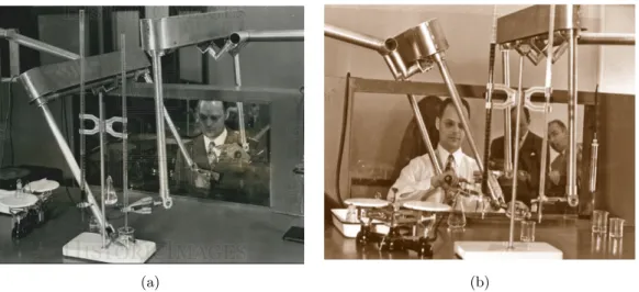
The first modern teleoperation system was developed between 1940’s and 1950’s addressing the nuclear research by Raymond C. Goertz in the Argonne National Laboratory where a master-slave manipulator addressed to chemical and nuclear material handling in the first nuclear reactor [12] was developed. The need was obvious. The radioactive nuclear material has to be manipulated safely. The nu-clear material was placed in a ”hot cell” where the operator could manipulate it from behind shielded walls. The visual contact with the target was through a protective window and/or a mirror. The first teleoperation system was completely mechanical. Master and slave were connected by gears, linkages, and cables these systems allowed the operator to use natural hand motions and transmitted forces and vibrations through the connecting structure. The system was clearly limited by the distance between the operator and environment and required the use of kinematically identical devices, see Fig. 2.4. Goertz quickly recognized the value of electrically coupled manipulators. The mechanical manipulators were soon re-placed by electro mechanical servos [13]. In 1954, Goertz’s team developed the first electro mechanical manipulator controlled by an array of on–o↵ switches to activate various motors and move various axes. The Goertz’s work laid the foun-dations of modern telerobotics and bilateral force-reflecting positional servos. After this, the teleoperation of manipulators and mobile vehicles extended rapidly to new branches where the advantages of teleoperation techniques could be uti-lized.
At the beginning of the 1960s the e↵ects of time delay on teleoperation started to become a topic of research. The concept of supervisory control, that will be
(a) (b)
Figure 2.4: Raymond C. Goertz in the early 1950s handling radioactive material using the first (mechanical) teleoperator.
Figure 2.5: The telerobotic system CRL Model M2 developed by the Oak Ridge National Laboratory and used by NASA in deep space assembly applications (1982).
detailed in Sec. 3.1.3 was introduced and inspired the next years of development [1].
The first telerobotic system implementing force feedback with separated master and slave electronics was the model M2 (1982), shown in Fig 2.5, of the Central Research Laboratory. It was developed together with the Oak Ridge National Laboratory and was used for some time for a wide range of demonstration tasks including military, space or nuclear applications. NASA tested the model M2 for remote assembly in space with excellent results.
Still in the field of space applications a dual-arm force reflecting telerobotic sys-tem was developed by Bejczy et al. at the Jet Propulsion Laboratory (JPL). For
Figure 2.6: JPL ATOP control station (early 1980s).
the first time in history kinematically and dynamically di↵erent master and slave systems were used, requiring control in Cartesian space coordinates (the same approach is used in the proposed teleoperation control schemes for mobile ma-nipulators discussed in Chapter 4). Figure 2.6 shows the master control station with its two back-drivable hand controllers. This system was used for simulating teleoperation in space.
In the 1980s and 1990s, the attention of the research community on teleoperation systems for space exploration was at the highest stage and started shifted also to other areas such as medicine and undersea/deep-sea exploration. The deep oceans are even today considered too hostile for humans so that most of the deep-sea op-erations are made with teleoperated submarines called Remote Operated Vehicles (ROV). Often ROVs are equipped with telemanipulators in order to perform un-derwater work tasks. The growth of the Internet and its use as a communication medium fueled further the trend of looking for new applications for telerobotics, adding also new challenges. Novel commercial haptic devices (e.g. the Phantom device [14], see Sec. 2.4.1) were introduced pushing up research activities in haptic applications and virtual reality.
In 1993 the first telerobotic system was flown in space with the German Spacelab Mission D2 on board the Space Shuttle Columbia. The robot technology experi-ment (ROTEX) demonstrated remote control of a space robot by means of local sensory feedback, predictive displays, and teleoperation [15]. The system could not be considered a bilateral system since only a one-way communication was em-bedded. The round trip delay was 6–7 s, such that it was not feasible to include force feedback into the control loop.
Figure 2.7: ROTEX, the first remotely controlled robot in space (1993). Telerobot in space and ground operator station. (Courtesy of the German Aerospace Center, DLR).
Figure 2.8: Operation Lindberg. The first transcontinental telerobotic surgery (2001).
Computer Motion demonstrated the feasibility of telerobotic systems even in the delicate field of surgery [16]. A surgeon in New York (USA) used a ZEUS sys-tem to perform a laparoscopic cholecystectomy on a patient located in Strasbourg (France), as depicted in Fig. 2.8. The system did not include force feedback, so the surgeon had to rely on visual feedback only.
(a) Da Vinci surgical system
(b) Da Vinci master device
Figure 2.9: The Da Vinci surgical system.
2.3
Range of application
2.3.1 Telesurgery
A quick look to the history of telerobotics briefly summarized in Section 2.2 points out that such systems can be applied to a variety of areas [17]. Telerobotic systems have been motivated by issues of human safety in hazardous environments (e.g. nuclear or chemical plants), the high cost of reaching remote environments (e.g. space), scale (e.g. power amplification or position scaling in micromanipulation or minimally invasive surgery), and many others. In the following some of the most successful cases of use are provided. A typical modern application of teleoperated robotic systems is represented by assisted surgery. In Fig. 2.9 the Da Vinci robot developed by the Intuitive Surgical company is shown. The surgeon safely and precisely controls the surgical tools by means of two haptic joysticks plugged to the thumb and the index of both hands (avoiding in this way dangerous issues related to human hand’s tremor, see Fig. 2.9(b)). The system also provides to the user an immersive 3D view of the scene where the tools are operating.
Nowadays a variety of minimally invasive surgical interventions are made by the help of the Da Vinci system: it can perform a variety of laparoscopic surgeries which involves scaling the surgeon’s actions into very small movements over a very small communication-delay.
Telesurgery over great distances is still on an experimental stage. In 2001, a team of surgeons from Johns Hopkins University in Baltimore (US) operated on 17 patients at Rome’s Policlinico Casilino University (Italy). In seven of the 17 procedures, the telesurgical connection was stopped and the operations were continued only from the remote site. Two of the 17 were converted to open surgery and during one of the kidney-related procedures problems arised with the manual control of the robotic device. Therefore not all the cases were fully teleoperated and the presence of a surgeon on site is needed in case unexpected problems arise. Anyway it’s easy to image a not so far future in which surgeons could operate on a patient from another location all around the world. Other examples of teleoperation in transatlantic surgery can be found in [18], while other generic medical applications in [19] and [20].
2.3.2 Underwater exploration
In the area of underwater applications, teleoperation is used in o↵shore oil ex-ploration, inspection and maintenance on drill heads, oil platforms and pipelines, marine biology experiments, geological surveys, archaeological search and recovery and classified navy tasks [21]. Americans, British, Japanese have led in this area [8]. ROV often are used in two-arms configurations: one fixed in the structure for stability and the other to perform tests and maintenance [22]. One of the earlier control architectures for underwater manipulator with force feedback is presented in [23].
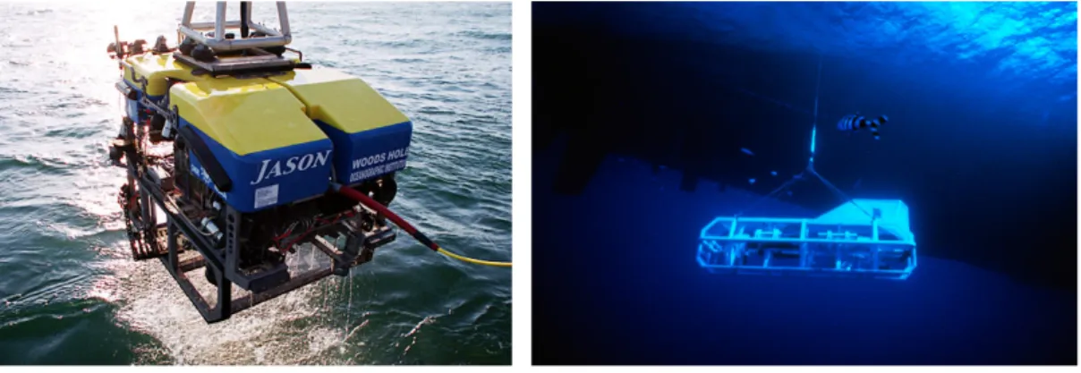
The Jason ROV shown in Fig. 2.10 that was controlled remotely to locate Ti-tanic (but it was later lost at sea). This system was developed as Argo-Jason project at the Woods Hole Oceanographic Institute and named after Jason and his Argonauts of Greek mythology [24]. The name Argo identifies a heavy passive assembly of high-energy sonar and photographic equipment suspended by up to 6000 m of cable from its support ship, while the telerobot Jason maneuvers on a flexible cable within easy return range from Argo, all controlled from the surface. Jason is programmed with a variety of supervisory control modes (see Chapter 3), and also makes use of some sophisticated techniques such as sliding-control to compensate for unmodeled dynamics common in deep-sea environments.
(a) The Jason ROV. (b) The Argo sonar and photographic equipment.
Figure 2.10: The remotely controlled Jason ROV (Fig. 2.10(a)) and the system of television cameras and sonars Argo (Fig. 2.10(b)). Both were used to locate the Titanic
in 1985.
2.3.3 Space exploration
Space robotics is a classic application, in which distance is the dominating barrier (see Sec. 2.1). The human operators can remotely control robots to perform dif-ferent tasks in the outer space. It can significantly reduce the cost of operations like assembly, maintenance, repairs. More importantly, it can reduce the risk of safety issues for astronauts [25].
The NASA rovers on Mars are a famous example. Due to the time delay of several minutes, the rovers are commanded using supervisory control (see Sec. 3.1.3), in which the human operator is defining the goal of a movement and the rover achieves the goal by local autonomy using sensory feedback directly [26].
The German technology experiment ROKVISS (Robot Component Verification on ISS) is the most advanced telerobotic system [27]. Launched in 2004, it is installed outside the Russian module of the international space station. In this experiment advanced robot components of a slave system, including torque sensors and stereo video cameras, are validated in real space conditions. Due to a direct communica-tion link between the space stacommunica-tion and the operator stacommunica-tion at DLR (Germany), the time delay was reduced to about 20 ms allowing a bilateral control architecture with high-fidelity force feedback to the operator [28] (Fig. 2.11).
Figure 2.12, shows the telemanipulation system built by the German Aerospace Research Center (DLR), conceived to support astronauts during maintenance op-erations in the Space Station. [29].
The master (see Fig. 2.12(a)) is equipped with two anthropomorphic arms that can be plugged to the wrists of the operator. An input device for the hands con-trol is mounted to the flanges of the two arms. The operator can wear a mask
Figure 2.11: ROKVISS, a space telerobotic system in which a ground operator by means of stereo vision and haptic feedback controls a slave robot place in the proximity
of the ISS (International Space Station).
(a) Master: HUG
(b) Slave: SpaceJustin
with a binocular screen to fell immersed in the augmented reality. The slave (see Fig. 2.12(b)) consists of two torque controlled anthropomorphic arm/hand sys-tems and a actuated head. The head has two degrees of freedom and is equipped with a stereo vision system that streams in realtime to the operator. The tele-manipulation behavior is realized by means of a cascade of an admittance and an impedance controller block [30].
The operator apply forces to the master arms that are acquired and converted to joints references velocities for the master arms. The current poses of the master TCPs are calculated by means of the forward kinematic and are used as references for the slaves arms. The pose errors are evaluated as the di↵erences of the current TCP poses of the master and the slaves arms. They are used as input for the impedance controller block that translate the pose errors to torques for the joints of the slave arms.
2.3.4 Other applications
Today telerobotics systems are applied to a variety of di↵erent fields that is im-possible to list all the im-possible applications in this document.
Good results of teleoperation of mobile robots are addressed in [31–33]. The hu-man operator can remotely control one or several mobile robots to perforhu-mance di↵erent tasks such as formation, co-transportation and multi-robot exploration. There are also many other applications where teleoperation has been applied. These applications include nano-manipulation [34], entertainment and education [35], forestry [36], excavation [37] and many others.
2.4
Haptic devices
This section focuses on specific robotic devices, known as haptic interfaces that, used as master in telerobotic systems, allow human operators to experience the sense of touch in remote environments. As mentioned in Sec. 2.1, force feedback can considerably improve the performance of a master-slave teleoperation system providing the operator with sufficient kinesthetic information about the remote environment.
Admittance devices sense the force applied by the operator and constrain the oper-ator’s position according to the actual dynamics of the slave robot. This approach is currently under investigation mainly in teleoperation of aerial vehicles [38, 39]. In contrast, an impedance haptic device senses the position of the operator, and then applies a force vector according to the physical interaction occurring between the slave robot and the remote environment. In the following we will only refer to impedance-type haptic interfaces.
The force vector imposed by the slave robot on the remote environment is reflected back and imposed by the master on the operator’s hand helping him/her to carry out the requested manipulation task. Hannaford et al. [40] compared both task completion time and level of force used for a variety of teleoperation tasks as well as a variety of control modes:
• Position control with visual but no force feedback;
• Regular visual feedback plus force feedback by means of visual display; • Visual plus kinesthetic (conventional bilateral force) feedback;
• ”Shared control” intended as: force feedback is imposed or suppressed as a computer-based function of object contact, recent past forces applied in all degrees of freedom;
• Bare-handed manual control;
Massimino and Sheridan (1994) [5] showed how mean completion time in such tasks is significantly reduced by force feedback independently of visual parameters such as frame rate and spatial resolution of the image.
While force reflection has been accepted in many applications like remote handling of nuclear and toxic wastes, where master-slave positions are considerably close, in all those applications where there is a significant time delay in the control loop (e.g. space applications or transoceanic telesurgery), force feedback produces dangerous instability e↵ects. In all those applications where force feedback is applied (in order to augment the sense of telepresence and increase task performance) haptic interfaces play a fundamental role as the master device. Such a device is able, not only to send motion commands to the slave, but also to display force information to the operator (see Fig. 2.3).
Generally speaking, from a kinematic point of view, there are two main types of haptic interfaces:
• Serial haptic devices: characterized by a serial-structured design. The end-e↵ector is mechanically connected to the robot’s base by a single open kine-matic chain;
• Parallel haptic devices: characterized by a parallel-structured design. The en-e↵ector is connected to the base by a number of kinematic chains.
When applied to a teleoperation systems both have some advantages and disad-vantages [41] that will be further discussed in Chapter 3.
In the following the state of the art of some well known commercial solutions available on the market as well as research results for both serial and parallel mechanisms is provided.
2.4.1 Serial kinematic structure
In 1977, Teleoperator System Corporation developed a bilateral force-reflecting servo master-slave manipulator called SM-229. SM-229 was the first member of a family of force-reflecting electric master-slave manipulators designed for pro-duction and it was designed to be maintainable by the users [42]. In 1980, Jet Propulsion Laboratory (JPL) and Stanford Research Institute (SRI) developed a universal, bilateral force-reflecting six-DoF manual controller [43].
The 7-DOF electrical Force Reflecting EXoskeleton Master was developed for re-search at Wright-Patterson Air Force Base. The system could provide an operator 25 N of force feedback at the handgrip using cables to transmit forces to the user’s hand. The design, control, and evaluation of a hyper-redundant serial hap-tic device is presented in [44]. A joyshap-tick-like general purpose haphap-tic interface is discussed in [45].
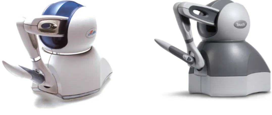
Several commercial solutions are also available on the market. The most widely used haptic interface is probably the PHANToM OmniR presented in [14],
devel-oped at MIT [14], and commercialized by GeomagicR under the name Geomagic Touch (formerly Sensable Phantom Omni) [46]. The device, shown in Fig. 2.13, is characterized by a six DoF serial kinematic chain and is available in a variety of sizes, three or six actuated DOF and allow interactions through a finger sled or a stylus. The same company also produces an high-end research device called Phantom Premium. It o↵ers low dynamic properties but also reduced range in terms of force rendering and reduced workspace. This device has been used in a variety of research experiments focused on robots teleoperation including the one presented in Chapter 4.
(a) PHANToM Haptic by SensAble Technologies (b) Touch Haptic by Geomagic
Figure 2.13: The Phantom Omni device by SensAble Technologies and the today’s Geomagic Touch by 3D Systems. This low-cost device senses motion in six degrees of
freedom and can apply forces in the x, y, and z directions to the stylus tip.
Another serial-designed commercial haptic is the Freedom 7 [47]. One of the disadvantages of such device is limited control sti↵ness due to the low physical damping present in the joints. A commercial version of Freedom 7 has been re-alized with the name Freedom 6S (MPB Technologies) [48]. The HapticMaster by MOOG [49] is the only admittance controlled haptic interface on the market. Other commercial solutions are distributed by Haption [50], MPB Technologies [51].
2.4.2 Parallel kinematic structure
A Gimbal-based parallel device has been presented in [52] (floating actuators) and [53] (non-floating actuators). In [54] a solution composed by a center handle con-necting four commercial Phantom Omni devices is proposed in order to provide six DoF force feedback while two 3 DoF parallel structures connected with a steer-ing handle are presented in [55]. The device proposed in [56] adopts a separable structure composed by lower and upper parallel mechanisms and it is specifically meant to address teleoperation of mobile manipulators. Commercial solutions in-clude the Force Dimension devices [57]: two series of haptic devices with parallel structures (omega.x and delta.x ) and a 7 active DoF device, sigma.7 with an extra force feedback DoF for grasping. The Novit Falcon [58] is a low-cost version of omega.3 meant to target the game industry but widely used also in research (Fig. 2.14).
Figure 2.14: Novit Falcon: commercial parallel haptic interface addressing the game industry but widely used in research.
Other exaples are produced by Quanser [59] and Butterfly Haptics [60] that pro-duced Maglev 200 : the only commercially available haptic interface based on the principle of Lorentz magnetic levitation.
2.5
Mobile manipulators
The importance and popularity toward mobile manipulators has grown in recent years [61]. In research, considerations have focused on the coordination of move-ments of the robot and the base since redundant degrees of freedom (DoF) are created by adding the moving base (as explained in the following).
In robotics the expression manipulator usually implies some sort of robotic arm involved [62]. A standard serial manipulator consist of a number of links connected with motor-driven joints, where at least one link is connected to the fixed base of the serial kinematic chain. When used as slave in telerobotics systems, the ma-nipulator make it it possible to manipulate objects in the remote environment and exchange interaction forces with it. The joints can either translate or rotate the links in order to place the end-e↵ector to a given position with a desirable orienta-tion. The main drawback in such robotic devices is clearly the limited workspace. Manipulators have been used in the industries since George Devol designed the first programmable robot in the mid-1950s.
On the other hand mobile robots have the ability to freely move in the envi-ronment making the available workspace potentially endless. The applications of mobile robots ranges from underwater and aerial vehicles, to ground robots, and are used both by the industry, military and civilian consumers. In the group of
(a) Pioneer robot: one of the most famous unicycle-like di↵erential drive wheeled mobile robot widely used in research.
(b) Pioneer robot with embed-ded serial manipulator.
Figure 2.15: Figure 2.15(a) shows a standard di↵erential drive mobile robot while Figure 2.15(b) shows the same robot equipped with manipulation capabilities.
ground vehicles the wheeled mobile robots are far the most common. A popular mobile robot used in research is the Pioneer robot shown in Fig. 2.15(a). It is driven by a di↵erential drive actuation system and presents a 3 DoF unicycle-like kinematic model.
Mobile manipulators represent the integration of this two type of systems in a single robotic device (Fig. 2.15(b)). Generally speaking it is composed by a mobile platform with integrated manipulation capabilities, provided e.g. by robotic arms with proper grasping/manipulation tools mounted on it. Such a combined robotic devices make it possible to extend the manipulator’s workspace to infinite. The integration of the two di↵erent robotic devices also introduces new challenges. The combination of a mobile platform and a multi-link manipulator creates re-dundancy because the sum of the degrees of freedom of the mobile base and the manipulator is generally greater than six. This implies that a particular point in the environment can be reached by the end-e↵ector by moving the manipulator, by moving the mobile platform, or by a combined motion of both. In other words there exists an infinite set of solutions in the joint space, for a given end-e↵ector configuration. It is then possible to change the robot configuration without a↵ect-ing the six DoF pose of the end-e↵ector. A complete modela↵ect-ing and control aspects analisys related to mobile manipulators can be found in [63].
Other research challenges in mobile robots teleoperation are related to the di↵erent kinematic models of the mobile platform and the manipulator. The manipulator
Figure 2.16: Mobile robot with omnidirectional wheels.
is usually a holonomic system while the mobile platform may be subject to non-holonomic constraints. A system subjected to nonnon-holonomic constrains is limited in the directions that an instantaneous act of motion can be performed. In other words a constraint is said to be nonholonomic if there exists a limitation on the velocity (velocities perpendicular to the wheel’s rolling direction are not allowed) but not in the configuration vector (i.e. the configuration that the robot can rich in the environment).
The end-point on a serial manipulator with six (or more) DoF instead, can apply a linear (and/or rotational) velocity in any direction (around any axis in space), but its configuration vector is limited by the dimension of its workspace. Mobile ma-nipulators override the holonomic contraints proper of fixed-base manipulator ex-tending their workspace to infinite. A mobile manipulator has the same reachable area than an infinite numbers of fixed-base manipulators along the path where the mobile base can move, which is insted still nonholonomically constrained. Many studies have been conducted on the whole-body modeling and control of nonholo-nomic mobile manipulators. There are commonly two ways to model the kinematic system with nonholonomic constraints. One way is to directly add the constraints to the velocity kinematic model [64, 65]. Another way is to model the system to explicitly entail the admissible motions with respect to the nonholonomic con-straints [66, 67].
The redundancy resolution methods for standard fixed-base manipulators can then be extended to the nonholonomic mobile manipulator with methods like the Ex-tended Jacobian method [68].
A common way to avoid nonholonomic constraints proper of mobile robots is the use of omni-directional wheels, shown in Fig. 2.16. In this kind of wheel, a series of rollers are attached to its circumference with axis of rotation placed at 45 degrees to the plane of the wheel and at 45 degrees to the line through the centre of the roller and parallel to the axis of rotation of the wheel.
Considering a four-wheeled configuration, like the one shown in Fig. 2.16, alter-nating wheels with left and right-handed rollers, in such a way that each wheel applies force roughly at right angles to the wheelbase diagonal, the vehicle is sta-ble and can move in any direction and turn by varying the speed and direction of rotation of each wheel. The following actions related to the wheel’s actuations are allowed:
• Moving all four wheels in the same direction causes forward or backward movement;
• Moving the wheels on one side in the opposite direction to those on the other side causes rotation of the vehicle (without causing any translation);
• Moving the wheels on one diagonal in the opposite direction to those on the other diagonal causes sideways movements;
Combining these actions permits to obtain three completely decoupled DoF (trans-lations along x and y axis and rotation ✓ around z axis) and allows the vehicle to perform motions in any direction with any rotation.
The use of omni-wheels permits to obtain a mathematical model of the mobile ma-nipulator in which the 3 decoupled DoF of the mobile platform are considered as new joints and links of a standard redundant manipulators (two endless prismatic joints and one infinite rotary joint) and to extend the traditional control methods for the standard manipulators to the mobile manipulators. However, when imple-menting these control methods to the actual mobile manipulators many problems occur seriously a↵ecting the control performance of the mobile manipulators in terms of motion accuracy [69]. These issues will be discussed in Sec. 3.3.1.
2.5.1 KUKA youBot
The KUKA youBot was introduced at the Automatica conference in 2010 in Mu-nich. The hardware is entirely developed by KUKA. The software was created as part of the European Best Practices in Robotics, or BRICS, project, funded under the EU’s FP7 robotics framework. It is a mobile manipulator that was pri-marily developed for education and research. As any other mobile manipulator, it consists of two main parts [70]:
• Omni-directional mobile platform (Fig. 2.17(a)): consists of the robot chas-sis, four omni-wheels (described in Sec. 2.5), motors, rechargeable battery
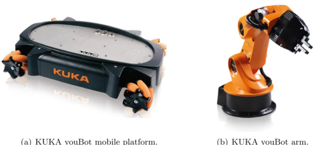
(a) KUKA youBot mobile platform. (b) KUKA youBot arm.
Figure 2.17: The KUKA youBot mobile manipulator composed by a omni-directional mobile platform Fig. 2.17(a) and a 5 DoF robotic manipulator Fig. 2.17(b).
and an on-board PC running Ubuntu Linux and ROS (Robot Operating System). The wheels motor controllers of can be accessed via Ethernet and EtherCAT both form the on-board PC and an external workstation. An extra Ethernet slot can be used to connect the on-board PC to a LAN via network cable. The overall mobile base weight is 20 Kg with a payload of 20 Kg as well. The geometric dimensions are: length 580 mm, width 380 mm and height 140 mm. The velocity range goes from a minimum of 0.01 m/s to a maximum of 0.8 m/s.
• The manipulator (Fig. 2.17(b)): it is characterized by a five DoF (defective) serial kinematic chain (shown in Fig. 2.18) and a two-finger gripper with a 20 mm stroke and a 70 mm range. Similar as for the base, the motor drivers of each individual joint can be accessed via Ethernet and EtherCAT. If connected to the mobile platform, the arm can be controlled by the on-board PC. Alternatively, the arm can be controlled without the mobile platform by using an external workstation connected via Ethernet cable. The total arm’s weight is 5.3 Kg with a nominal payload of 0.5 Kg. The available workspace is an ellipsoid-like portion of space with x and y axis equal to 540 mm and z axis equals to 655 mm. The maximum joints rotational speed is 90 deg/s. Additional sensors and general purpose hardware can be mounted on the robot. The most common integrations involve the use of standard vision sensors (2D cameras), range finders, laser scanners and 3D vision sensors.
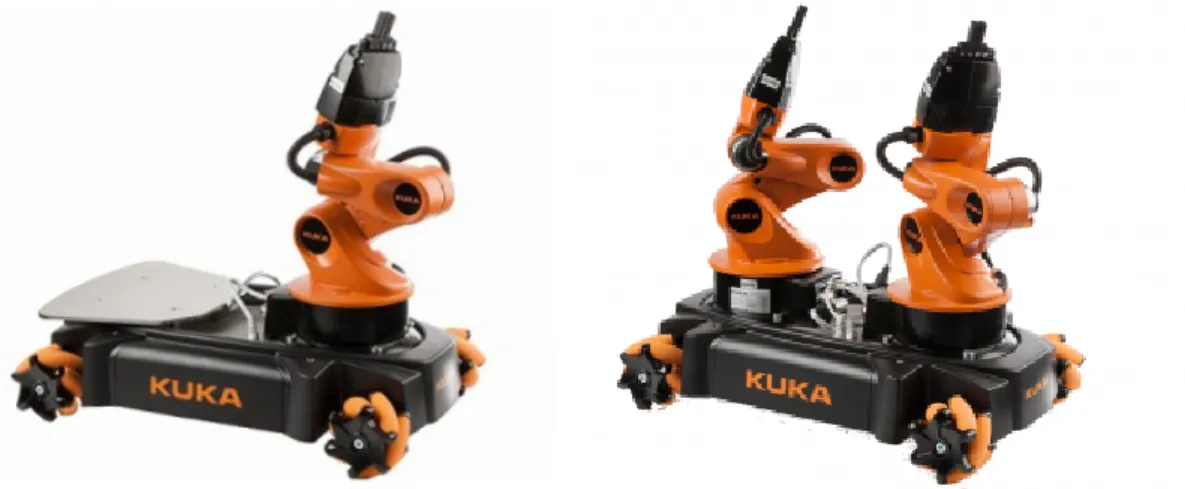
The robot is available in a single-arm configuration with a metal plate installed nearby the arm on the mobile base for holding objects and in a dual-arm con-figuration for advanced bi-manual manipulation tasks. Both solutions are shown
Figure 2.18: Overview of the serial kinematic chain of the KUKA youBot arm. The figure illustrates joints limits and links length.
(a) KUKA youBot sigle-arm configuration (b) KUKA youBot dual-arm configuration
Figure 2.19: The KUKA youBot mobile manipulator available in single-arm config-uration Fig. 2.19(a) and dual-arm configconfig-uration Fig. 2.19(b).
in Fig. 2.19. The single-arm configuration is the one used in the experiments discussed in Chapter 4.
Design and Control Issues in
Robotic Teleoperation
3.1
Degree of autonomy
Although the research in robotics has gone a long way towards making robots more and more intelligent and able to execute complex tasks autonomously without the help of human operators, the native perception capabilities and decision making skills of the human being cannot be left aside when dealing with operations in remote and unstructured environments. For this reason, teleoperation of robotic systems still plays an important role in many applications (see Sec. 2.3). As a matter of fact in recent years mainly two research lines have been followed up in order to widen the fields of application of robots. First of all, a higher degree of autonomy has been recognized as an essential requirement in order to reduce the need for human supervision/control and to improve the capability of a robot to self-react to external stimuli, (e.g. the presence of obstacles with unknown positions and velocities) [6]. On the other hand, several tasks such as the manipulation of radioactive materials require the constant supervision of a human operator, that for safety reasons remotely operates an electro-mechanical device [71]. In this situation, the perception by the user of the interaction between the robotic device and the manipulated material is essential in order to successfully complete the required operation.
Several control schemes have been proposed in the literature [72]. These control methods are based on a number of di↵erent techniques for dealing with common problems that arise in this area of telerobotics. In order to achieve di↵erent degree of autonomy embedded in the slave robot (i.e. the ability to perform some kind
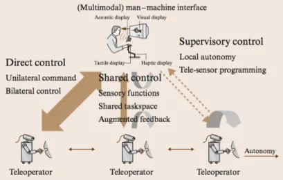
Figure 3.1: Di↵erent types of control architectures for telerobotics system depending on the degree of autonomy of the slave robot.
of operation in the remote environment without the intervention of the human operator) mainly three control architectures can be considered (Fig. 3.1):
• Direct Control • Shared Control • Supervisory Control
Direct control or manual control falls at one extreme, indicating that the user is controlling the motion of the robot directly and without any automated help. At the other extreme, supervisory control implies that user’s commands and feedback occur at a very high level and the robot requires substantial intelligence and/or autonomy. Between the two extrema lie a variety of shared control architectures, where some automated help is available to assist the user [1].
3.1.1 Direct control
The direct control architecture implies that the slave motion is directly controlled by the human operator by means of the master device. In this case the slave robot is usually referred to as telemanipulator (or teleoperator) and do not own any kind of intelligence or local autonomy.
The motion commands sent from the master to the slave, related to the master position displacement imposed by the user, can be computed and mapped on the slave side by means of di↵erent strategies depending on the kinematics of the slave
device. Roughly speaking, it is possible to define two main control approaches strongly oriented to the type of robot to be controlled [73]. In case of fixed-base manipulators, a common approach is the so called position-position while, in case of mobile robots, the same master displacement is mapped into velocity commands (position-velocity).
In the following, the two basic control schemes are briefly reported and discussed. A combination of both schemes has been used in the hybrid scheme addressed to mobile manipulators presented in Chapter 4.
3.1.1.1 Position-position control
The position-position teleoperation control scheme is among the most simple schemes adopted in robots teleoperation (mostly applied to fixed-base manipu-lators). It has been widely used to perform teleoperation tasks requiring object manipulation and more in general involving interaction with remote environments. This control scheme can be based on a direct kinematic mapping between master and slave devices (involving control in the joint space, i.e. physically identical devices) or can implies control in the workspace to overcome possible mismaches in the master/slave kinematic structures. [74].
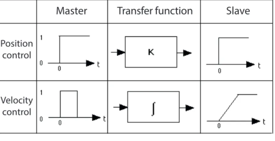
This control scheme maps the position displacement of the master device, directly imposed by the operator, to a reference signal for the slave position controller. It is particularly suited in control schemes where the human operator controls object positions directly. The transfer function from human operator to the slave robot movement in position control is a constant (i.e. a zero order transfer function, see Fig. 3.2). A proper scaling factor may be used to overcome possible di↵erent dimensions in master and slave workspaces.
3.1.1.2 Position-rate/acceleration control
Position-rate/acceleration control on the other hand, controls movement through velocity or acceleration. In this scheme the displacement of the master device defines the velocity or the acceleration of the slave: In other words the transfer function from human input to the slave robot movement is an integral (or double integral) (i.e. first order or second order transfer function, see Fig. 3.2). This type of control architecture is particularly suited for mobile robots control (ground, aerial or underwater vehicles) to overcome the mismatch between the master and the slave workspaces dimension.
For six-degree-of-freedom DoF applications, i. e., when the slave needs to be controlled in translation and orientation, a 6D-Space Mouse or alternatively often two joysticks are used as master device for translation and orientation respectively. Acceleration and rate control can require considerable e↵ort for the operator to reach and hold a given target location. Obviously, users can more accurately position a system under rate control than under acceleration control [75]. Indeed acceleration control necessitates users to regulate a second-order system versus a first-order system for rate control.
3.1.1.3 Comparison
In the following a comparison between position-position and position-rate controls is taken into consideration. In general, position control has been proven to be more efficient in task where short and precise movements are involved, (i.e. manipu-lation tasks) [76].In [77] the authors found out that the position-position scheme can be 1.5 times faster than the position-rate control when the master and slave workspaces are similar. As illustrated in Fig. 3.2, the input control patterns for rate control are more complex than for position control. As a matter of fact in order to cause a change of state from one level to another, a pair of reversal actions has to be given. This might result in being less intuitive then the position-position scheme in case of small displacements.
The position-rate scheme gives better performance when the slave workspace is (much) larger than the master’s one. and therefore this control scheme is very suitable in case of teleoperation of mobile robots with infinite workspace. Posi-tion control also has its conceivable disadvantages relative to rate control. First, it transfers all human limb movements, whether voluntary or involuntary, to the ma-nipulation task. In contrast, the low pass filtering e↵ect introduced by the integral function in a rate control scheme will suppress many high frequency involuntary noises. Second, by definition, rate control lets the user control the velocity of the controlled robot, resulting in smoother movement. With position control, on the other hand, it is more difficult to maintain control of the velocity of the move-ment, increasing the likelihood of jerky motions. Third, with position control, the maximum operating range is limited while rate control has an e↵ectively unlimited operational range.
Hybrid position-position and position-rate schemes, that try to take advantage from both approaches, have been proposed in the literature. For example, the case of mobile robots has been addressed in [78], while [76, 79] considers a fixed-base
Master Transfer function Slave Position
control
Velocity control
Figure 3.2: Transfer function between master and slave in position-position and position-velocity control schemes.
simulated manipulator, and [80, 81] a virtual environment interaction. The idea behind hybrid position-position and position-rate controllers is obviously to ex-ploit the precision of the first and the ability to cover large distances of the latter scheme.
3.1.2 Shared control
Direct control may became impractical in case of not negligible time delays in the communication channel of the telerobotic system (e.g. space or internet-based applications) or in case it is desired to reduce operator workload. To enable telep-resence in long-distances telerobotics systems, a so called shared autonomy control [82, 83] appears to be convenient, as it lightens the e↵ort required to the operator [84]. Shared control is based on local autonomous sensory feedback loops [85] at the slave site. The human operator can produce gross motion commands using a kinesthetic haptic device (Sec.2.4), which are fine-tuned by the teleoperator. In applications with large time delays the shared autonomy concept can be even related to a so called task-directed approach [86]. The intelligence is distributed between the operator and the slave robot such that each controls his specific sub-task independently. An example can be seen in the telesurgery system shown in Fig. 3.3 [1], where the autonomous skills of the slave robot controls and compen-sates the patients movement, while the surgeon controls the operation itself on a virtual stabilized patient [87].
In other application of shared control, like the execution of an anthropomorphic grasp task, the user could, for example, simply manifest the intention to grasp
Figure 3.3: An example of application of the shared control concept in telesurgery.
an object, while the system autonomously plan the grasp configuration of the an-thropomorphic hand. This can be done based on the actual relative pose of the arm with respect to the object, the object shape and the hand kinematic. The implementation of such technique becomes much more feasible if a reactive and accurate vision system able to retrieve objects and obstacles informations, is avail-able on the slave robot [30].
Virtual elements, such as virtual surfaces or generic virtual constraints, can be also imposed to the user. These fixtures help the operator perform manipulation tasks by limiting movement into restricted regions and/or influencing movement along desired paths. Control is thus shared at the master site, taking advantage of a priori-knowledge of the system or task to modify the user’s commands and/or to combine them with autonomously generated signals.
3.1.3 Supervisory control
An even higher-level approach, compared to shared control, is the superisory con-trol [88]. In supervisory concon-trol the operator is limited to act as a supervisor of the telerobotic system and decides if/when/how to act and what to do. The intelli-gence is truly distributed between the operator and the slave robot [89]. The user specifies only high-level task operations, local sensory feedback loops are used by the robot system, while global task-level jobs have to be specified interactively by a human operator. In this approach the robot can be teleprogrammed on a task directed level. The teaching of a robot system occurs not on the joint or Cartesian
manipulator level but on a higher language level, i. e. the operator plans activities at a level and the slave robot independently perform the task.
Such a control architecture sometimes includes two control loops working in paral-lel. One loop running on the real remote system, which contains internal feedback for local autonomy. The other loop, running on the local site, implements a sim-ulated environment which is structurally equivalent to the real system. Since the simulated environment is not a↵ected by any delay in the communication channel, it is predictive with respect to the real system. The main feature of this telerobotic concept is to replace the time-delayed visual feedback with predictive stereo graph-ics including sensor simulation, providing a supervisory control technique that will allow a shift of more and more autonomy and intelligence to the robot system. This provides the operator with an efficient interface to setup task to configure the task control parameters and debug an entire job execution. Such a telerobotic architecture requires unique tools to implement the required functionality. A so-phisticated simulation system has to be provided to emulate the real robot system (including the simulation of sensory perception within the real environment). In all those applications with large time delays, e.g. in space and undersea appli-cations, this approach has advantages because under time delays of a few seconds, is not feasible for the human operator to handle the robot’s movements using a standard direct control approach.
3.2
Master/Slave kinematics comparison
3.2.1 Kinematically equivalent mechanisms
Considering a telerobotics system running under a position-position direct control modality (described in Sec. 3.1.1.1), the simplest scenario involves a master-slave system kinematically equivalent between the two robots. In this case the control of the slave device can be based on a direct mapping between the joint state vector qm of the master robot (imposed by the user) sent to the slave device as a joint state vector position setpoint qsd for the slave’s joints position controllers:
qsd = qm (3.1)
Depending on the controllers architecture, the joint velocities of the master and the slave robots may be similarly related, taking derivatives of eq 3.1.
3.2.2 Kinematically unequal mechanisms
Master and slave robots may, in many cases, present completely di↵erent kinemat-ics structures. This is a common situation when the slave robot is a mobile robot or in particular a mobile manipulator. The master is connected to the human operator which usually has a limited available workspace with respect to the slave workspace. As a result a direct mapping in the joint space between the two robots is not feasible.
In such scenarios a usual solution is to implement a master-slave mapping in the workspace as stated by the following equation:
xsd = · xm (3.2)
Rsd = Rm (3.3)
where xsd and xm are the desired 3D position of the slave robot and the actual 3D position of the master (imposed by the user) and is a proper scaling factor needed to overcome the di↵erent dimension between the master and the slave workspace. Rsd and Rm represent the desired rotation matrix of the slave device and the current rotation matrix of the master (imposed by the user) respectively. Again velocities and angular velocities may be connected if needed.
It is important to remark that, in case of the slave device presents a lower number of DoF with respect to the master device, the di↵erent kinematics may introduces Cartesian configurations of the master that are not physically reachable by the slave. Hybrid approaches between joint space mapping and workspace mapping can then be used. This is the case of the teleoperation algorithm proposed in Chapter 4.
3.3
Motivation and related issues
3.3.1 Mobile Manipulators teleoperation
As described in Sec. 2.3, the range of application of telerobotic systems is consid-erably extended. The native perception capabilities and decision making skills of the human being cannot be left aside when dealing with operations in remote and unstructured environments (such as space, surgery or nuclear materials handling). Mobile manipulators like the KUKA youBot (presented in Sec.2.5.1) are promising solutions because they significantly increase the workspace of the slave manipulator