S
CUOLA
S
UPERIORE
S
ANT’
A
NNA
D
OCTORAL
T
HESIS
Ergonomics of Wearable Robots
Author:
Supervisor:
Nicolò d’Elia
Prof. Nicola Vitiello
A thesis submitted in fulfilments of the requirements
for the degree of Doctor of Philosophy
in
The BioRobotics Institute
i
Acknowledgments
Firstly, I would like to express my sincere gratitude to Prof. Nicola Vitiello for the continuous support of my Ph.D study and related research, for his motivation, and above all patience. His guidance helped me in all the time of research and brought me to the writing of this thesis.
Besides my direct supervisor, I would like to thank the external supervisors and thesis committee: Prof. Raffaele Molino Lova, Prof. Maurizio Ferrarin, and Dr. Federica Vannetti for their insightful comments and encouragement, but also for the hard questions which encouraged me to widen my research from various perspectives.
I thank my fellow labmates at the institute of Biorobotics and Fondazione Don Carlo Gnocchi for the stimulating discussions and for the help during the whole time of my Ph.D. In particular, I am grateful to Andrea Parri who supported and guided me during both experimental activities and papers writing.
Last but not the least, I would like to thank my parents and my girlfriend Marta for supporting me spiritually throughout the writing of this thesis and my life in general.
iii
List of Publications
Journal Publications
d’Elia N, Parri A, Vannetti F, Pasquini G, Macchi C, Crea S, Vitiello N. Evaluation of the physical interaction with an active pelvis orthosis in multiple gait tasks. Journal of
NeuroEngineering and Rehabilitation. Under preparation.
d’Elia N, Vannetti F, Cempini M, Pasquini G, Parri A, Rabuffetti M, Ferrarin M, Molino Lova R, Vitiello N. Physical human-robot interaction of an active pelvis orthosis: toward ergonomic assessment of wearable robots. Journal of NeuroEngineering and
Rehabilitation. 2017; 14:29. DOI: 10.1186/s12984-017-0237-y.
d’Elia N, Vannetti F, Cempini M, Pasquini G, Rabuffetti M, Ferrarin M, Molino Lova R., Vitiello N. Ergonomic assessment of an active pelvis orthosis. Gait & Posture. 2015;42,S18-S19.
Manti M, Hassan T, Passetti G, d'Elia N, Laschi C, Cianchetti M. A bioinspired soft robotic gripper for adaptable and effective grasping. Soft Robotics. 2015;2(3),107-116.
Conference Proceedings
Manti M, Hassan T, Passetti G, d’Elia N, Cianchetti M, Laschi C. An Under-Actuated and Adaptable Soft Robotic Gripper. In Conference on Biomimetic and Biohybrid
Systems 2015;64-74.
Hassan T, Manti M, Passetti G, d'Elia N, Cianchetti M, Laschi C. Design and development of a bio-inspired, under-actuated soft gripper. In 2015 37th Annual
International Conference of the IEEE Engineering in Medicine and Biology Society (EMBC). 2015; 3619-3622.
v
Abstract
In the field of human-centered robotics, exoskeletons are becoming relevant for addressing needs in the healthcare and industrial domains, both as tools for rehabilitation treatment and clinical assessment and for augmented reality applications (haptics or augmentation). Despite the increasing interest and number of developed prototypes and commercial systems, the design of exoskeletons still has many open issues, such as those related to the development of the physical human-robot interface. Owing to their close interaction with the user, safety and ergonomics are critical features that heavily influence the functionality and the dependability of a wearable robot. In general, these devices are designed to generate and transfer mechanical power to human joints: therefore, optimal kinematic coupling is required between the corresponding human and robot rotation axes.
Misalignment between the human and robot joint axes can cause undesired forces that overload human articulations, thus resulting in an uncomfortable or even painful interaction with the robot. Undesired forces originating from joint axis misalignments can also lead the orthotic shells of the exoskeleton to slide along the human limb segments, leading to unreliable assistive torque transmission and possible skin inflammation or even sores.
As a consequence, modern exoskeletons are provided with adjustable regulations and/or passive degrees of freedom (pDoFs), in accordance with recent ergonomic design principles for the development of wearable robots. However, the introduction of passive DoFs into the design of a WR is not free of drawbacks; the tradeoff between the degrees of laxity and the system complexity may affect the overall human-robot kinematics coupling. On the one hand, by increasing the degree of laxity of the powered joints, there is a risk of increasing the overall inertia and friction of the moving parts. On the other hand, a lack of adequate laxity partially affects the human-robot joint axis self-alignment
vi and thus hinders the spontaneous movement of the user. As a consequence, in the development and design of an exoskeleton, the assessment of its kinematic compatibility with user biomechanics is of paramount importance. In particular, it is important the evaluation of ergonomics. Anyhow, a systematic evaluation methodology for the assessment and benchmark of ergonomics is still missing in literature.
In this thesis, we propose a methodology for the assessment of ergonomics of wearable robots. In particular, by taking as a test bed an active pelvis orthosis (APO) for hip flexion/extension assistance, we carried out a set of experiments where we assessed ergonomics against three main factors at the same time: i) the deviation from natural walking (NW) kinematics deriving from wearing the device in transparent mode (TM)— the APO shadows the wearer in zero–torque control—and in assistive mode (AM) with different levels of assistance—i.e. the APO deliver torque to the wearer; ii) the stability of the human-robot interaction; and iii) the discrepancy between the human and robotic hip joint kinematics. These three factors led to the definition of three quantitative indicators:
The root mean square (RMS) of the difference of the human hip, knee, and ankle flexion/extension (f/e) angle between the NW and TM/AM conditions; we named these variables ‘human hip angle deviation’ (H-HAD), ‘human knee angle deviation’ (H-KAD), and ‘human ankle angle deviation’ (H-AAD), respectively.
The standard deviation (SD) of the relative displacements between the markers placed on the orthotic cuffs of the APO and those placed on their corresponding body segments; we named this set of variables ‘physical human-robot interface displacement’ (pHR-ID); (iv) the human joints’ ROM in the sagittal plane (hip, knee, and ankle) and in the frontal plane (only at the hip); and (v) spatio-temporal parameters (i.e., step length, stance time, and cadence).
The RMS of the difference between the APO hip f/e angle and the anatomical hip f/e angle; we named this variable ‘human-robot hip angle deviation’ (HR-HAD).
The proposed metrics was validated in two experimentations. In the first study, we reported the methods and results of an experiment with healthy users engaged in tasks of treadmill–based gait while the APO provided hip flexion-extension at different speeds and assistance levels. In particular we wanted to understand whether the pDoFs of the APO hip joint allowed an appropriate human-robot joint axes self-alignment.
vii The results show: (i) negligible interference of the APO in human kinematics under all the experimented conditions: H–HAD, H–KAD, H–AAD below 3.9°, 4.0°, 3.8° respectively; (ii) high stability (pHR-ID < 1 cm) between the APO cuffs and the corresponding body segments; and (iii) human-robot kinematics discrepancy at the hip flexion-extension joint (HR-HAD) remains below 7.2°.
Hence, APO mechanics and actuation have negligible interference in human locomotion. Human kinematics was not affected by the APO under all tested conditions. In addition, under all tested conditions, there was no relevant relative displacement between the orthotic cuffs and the corresponding anatomical segments. Thereby, the physical human-robot coupling is reliable. These facts prove that the adopted mechanical design of passive degrees of freedom allows an effective human–robot kinematic coupling.
In the second study, we reported the methods and results of the experiment with healthy users engaged in tasks of ground–level walking and stair ascending in ecological conditions (no treadmill). A new version of the APO (which feature halved weight and no intra/extra rotation pDoF) provided hip f/e at different speeds and assistance levels. The final goals of this study were: (i) test the applicability of the proposed metrics to different tasks and conditions of walking; (ii) compare and benchmark the ergonomics of the previous version of the APO with the new one.
The results show (i) negligible interference of the APO onto human kinematics in ground–level walking (H–HAD, H–KAD, H–AAD below 3.0°, 5.0°, 3.0° respectively) but non–negligible impact in stair ascending (H–HAD, H–KAD, H–AAD below 9.0°, 9.0°, 5.0° respectively); (ii) high stability (pHR-ID < 1 cm) between the APO cuffs and the corresponding body segments under both locomotion tasks; and (iii) HR-HAD below 8.0° and 9.0° ground–level walking and stair ascending respectively.
Two different conclusions regarding APO ergonomics can be reached for ground–level walking and stair ascending. In the case of ground–level walking, since the physiological kinematics is not severely altered (low H-HAD, H-KAD, H-AAD), pHR-ID are negligible (< 1 cm) and all subjects did not report discomfort while walking, we may conclude the APO to be ergonomic, regardless the possible JAxM. Interestingly, in ground level walking, the reduced self-alignment capability (with respect to previous version), do not bring a worsening in the ergonomics of the device in terms of the analyzed indicators.
viii Instead, in the case of stair ascending, we observed low (< 1 cm) pHR-ID, similar values of HR-HAD and no reported discomfort by the wearer, but natural kinematics seems to be relevantly altered. This result evidences a minor kinematic compatibility between the wearer and the robot suggesting a revision of its kinematic design for stair ascending tasks.
In conclusion, the proposed metrics proved to be a reliable tool to investigate the ergonomics of lower limb wearable robots and assess their performance. Furthermore, it can be a valid aid to benchmark and compare the several platforms which have been developed in the state of the art and will be developed in the future.
ix
Table of contents
ACKNOWLEDGMENTS ... I
LIST OF PUBLICATIONS ... III
ABSTRACT ... V
TABLE OF CONTENTS ...IX
LIST OF FIGURES ... XIII
LIST OF TABLES ... XIX
DISAMBIGUATION... XXIII
1 INTRODUCTION ... 1
1.1 PHYSICAL HUMAN-ROBOT INTERACTION IN WEARABLE ROBOTICS ... 2
1.2 ERGONOMIC KINEMATIC DESIGN OF WEARABLE ROBOTS ... 4
1.3 A NOVEL FRAMEWORK FOR THE EVALUATION OF THE ERGONOMICS OF A WEARABLE ROBOT ... 7
1.4 REFERENCES ... 9
2 PHYSICAL HUMAN-ROBOT INTERACTION OF AN ACTIVE PELVIS ORTHOSIS: TOWARD ERGONOMIC ASSESSMENT OF WEARABLE ROBOTS ... 13
2.1 INTRODUCTION ... 13
2.2 METHODS ... 16
2.2.1 Participants ... 16
2.2.2 Active Pelvis Orthosis ... 17
2.2.3 Experimental protocol ... 19
x
2.3 RESULTS ... 22
2.3.1 Spatio-temporal parameters ... 23
2.3.2 Kinematics ... 23
2.3.3 Physical human-robot interface displacements ... 28
2.3.4 Human-robot kinematics discrepancy ... 30
2.4 DISCUSSION ... 32
2.4.1 Spatio-temporal parameters ... 32
2.4.2 Kinematics ... 33
2.4.3 Physical human-robot interface displacements ... 34
2.5 CONCLUSION... 36
2.6 REFERENCES... 38
3 EVALUATION OF THE PHYSICAL INTERACTION WITH AN ACTIVE PELVIS ORTHOSIS IN MULTIPLE GAIT TASKS ... 43
3.1 INTRODUCTION ... 43
3.2 METHODS ... 45
3.2.1 Participants ... 45
3.2.2 Active Pelvis Orthosis ... 45
3.2.3 Experimental protocol ... 47
3.2.4 Data acquisition and processing ... 49
3.3 RESULTS ... 51
3.3.1 Spatio-temporal parameters ... 51
3.3.2 Kinematics ... 55
3.3.3 Physical human-robot interface displacements ... 61
3.3.4 Human-robot kinematics discrepancy ... 64
3.4 DISCUSSION ... 67
3.4.1 Kinematics ... 67
xi
3.4.3 Human-robot kinematics discrepancy and pHR-ID ... 71
3.4.4 Benchmark of the APO ... 72
3.5 CONCLUSION ... 73
3.6 REFERENCES ... 74
4 CONCLUSION ... 77
xiii
List of figures
FIGURE 1.1:TRANSLATION OF THE INSTANTANEOUS CENTRE OF ROTATION (ICR) OF THE GLENOHUMERAL SHOULDER JOINT DURING SHOULDER ABDUCTION.THIS SHOWS HOW HUMAN JOINT CENTERS OF ROTATION ARE NON
-STATIONARY.AN ERGONOMIC EXOSKELETON WILL HAVE TO COPE WITH SUCH ALTERATIONS OF THE HUMAN ANATOMICAL STRUCTURE DURING MOVEMENT.(ADAPTED FROM [7],©2008WILEY &SONS, WITH PERMISSION FROM WILEY &SONS)... 3 FIGURE 1.2:ILLUSTRATION OF THE CREATION OF INTERACTION FORCE AS A CONSEQUENCE FROM JOINT
MISALIGNMENTS BETWEEN EXOSKELETON AND HUMAN LIMB (A).DURING MOTION, THE EXOSKELETON SLIDES ON THE HUMAN LIMB.IF PASSIVE JOINTS ARE ADDED INTO THE STRUCTURE THOSE FORCES ARE NOT CREATED
(B), THE JOINTS COMPENSATE FOR THE SLIPPING OF THE DEVICE.(ADAPTED FROM [7],©2008WILEY &
SONS, WITH PERMISSION FROM WILEY &SONS)... 5 FIGURE 1.3:SELF-ALIGNMENT FOR EXOSKELETONS AXES IN A PLANER VIEW.(A)THE EFFECTS OF A SINGLE MISALIGNED
AXIS AT THE SHOULDER.DUE TO EXOSKELETON TORQUE TEX, THE ARM AND EXOSKELETON AXES ROTATE AN
ANGLE Α.IF THESE AXES ARE MISALIGNED, THE HUMAN JOINT HAS TO TRANSLATE RELATIVE TO THE
EXOSKELETON AXIS.IF THE AXES ARE fiXED, THIS MOVEMENT CREATES A RESIDUAL SHOULDER FORCE FSH, WHICH
IS DEPENDENT ON THE STIFFNESS OF SKIN AND BONE, AND AN EQUAL EXOSKELETON REACTION FORCE FEX.(B) TRANSLATING EXOSKELETON AXES PREVENTS THESE MISALIGNMENT FORCES.IF A MISALIGNMENT CAUSES A FORCE FEX, THE EXOSKELETON TRANSLATES UNTIL THIS FORCE IS GONE.TORQUES CAN BE APPLIED TO THE LIMB
FROM THE ROTATIONAL-STIFF LINKAGE MECHANISM.THE EFFECTS ARE THE SAME IN 3-D BY ADDING THE TWO OTHER ROTATIONAL AXES REQUIRING ONLY THE ONE fiNAL LINEAR AXIS.(ADAPTED FROM [10],©2009IEEE,
WITH PERMISSION FROM IEEE) ... 6 FIGURE 2.1: A)HUMAN SKELETON COVERED BY SOFT TISSUES. B)HUMAN BODY WITH WEARABLE ROBOTIC CHAIN
SCHEMATIC:(1) PASSIVE TRANSLATIONAL DOF,(2) ABDUCTION/ADDUCTION ROTATION PASSIVE DOF,(3)
INTERNAL/EXTERNAL ROTATION PASSIVE DOF,(4) ROTATION PASSIVE DOF,(A) PELVIS CUFF,(D)
List of figures
xiv
HUMAN BODY COUPLED WITH EXOSKELETON:(B) CARBON-FIBER PLATE,(C) SLIDING CARBON-FIBER PLATE,(G)
LATERAL EXTENSIBLE ARM,(H) THIGH LINKAGE,(I) THIGH CUFF.FOR THE SAKE OF CLARITY, ONLY THE RIGHT PART OF THE BILATERAL APO IS REPRESENTED. ... 17 FIGURE 2.2:ADAPTED LAMB MODEL MARKER SETUP.POSTERIOR SUPERIOR ILIAC SPINE LANDMARK, HIDDEN BY THE
EXOSKELETON, WAS RECONSTRUCTED THROUGH A MARKER PLACED ON TOP OF A PELVIS-ANCHORED STICK
(ENCIRCLED IN RED).RED ARROWS SHOWS WHICH MARKER ARE USED TO CALCULATE BODY-CUFF RELATIVE DISPLACEMENTS. ... 21 FIGURE 2.3:KINEMATICS AND KINETICS FOR ALL SPEEDS (SLOW (V1), SPEED SELECTED ACCORDING TO DYNAMIC
SIMILARITIES PRINCIPLE (V2), FAST (V3)) AND WALKING CONDITIONS (NATURAL WALKING –NO APO–(NW,
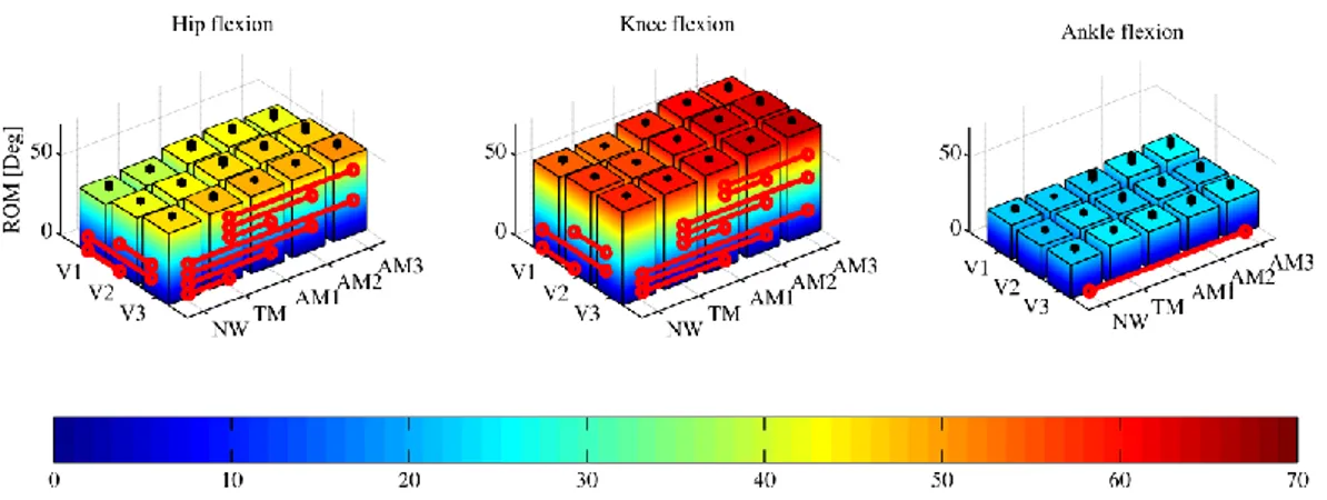
LIGHT GREEN DASHED LINES), TRANSPARENT MODE –APO SHADOWS THE WEARER-(TM, BLUE LINES), LOW ASSISTANCE (AM1, BLACK LINES), MODERATE ASSISTANCE (AM2, RED LINES), HIGH ASSISTANCE (AM3, DARK GREEN LINES)).EACH LINE REPRESENTS THE STRIDE AVERAGE AND ONE SD BAND FOR EACH TRIAL FROM ONE REPRESENTATIVE SUBJECT.FLEXION POSITIVE... 25 FIGURE 2.4:HIP, KNEE AND ANKLE FLEXION-EXTENSION ANGLE RANGE OF MOTION (ROM) FOR ALL SPEEDS (SLOW
(V1), SPEED SELECTED ACCORDING TO DYNAMIC SIMILARITIES PRINCIPLE (V2), FAST (V3)) AND WALKING CONDITIONS (NATURAL WALKING –NO APO-(NW), TRANSPARENT MODE -APO SHADOWS THE WEARER -(TM), LOW ASSISTANCE (AM1), MODERATE ASSISTANCE (AM2), HIGH ASSISTANCE (AM3)).EACH COLORED COLUMN IS THE AVERAGE ROM; BLACK COLUMNS REPRESENT ONE SD BAND.RED LINES SHOW SIGNIFICANT
(TWO-WAY ANOVA(P <0.05) WITH FISHER LSD POST-HOC) DIFFERENCES. ... 27 FIGURE 2.5:MEAN ±SD OF HUMAN HIP ANGLE DEVIATION (H-HAD, LEFT), HUMAN KNEE ANGLE DEVIATION
(H-KAD, CENTER) AND HUMAN ANKLE ANGLE DEVIATION (H-AAD, RIGHT) FOR ALL SPEEDS (SLOW (V1), SPEED SELECTED ACCORDING TO DYNAMIC SIMILARITIES PRINCIPLE (V2), FAST (V3)) AND WALKING CONDITIONS
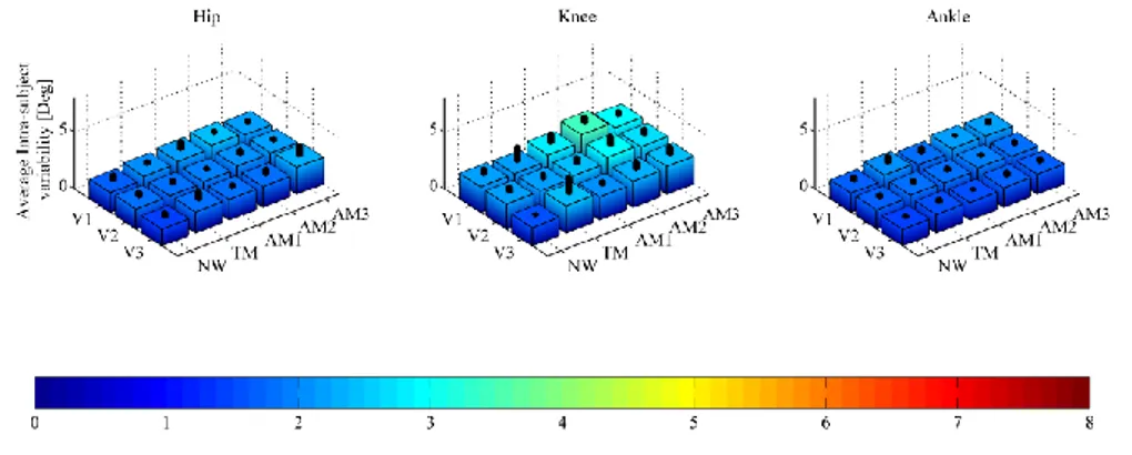
(NATURAL WALKING –NO APO-(NW), TRANSPARENT MODE -APO SHADOWS THE WEARER-(TM), LOW ASSISTANCE (AM1), MODERATE ASSISTANCE (AM2), HIGH ASSISTANCE (AM3)).BLACK COLUMNS REPRESENT ONE SD BAND.RED LINES SHOW SIGNIFICANT (A TWO-WAY ANOVA(P <0.05) WITH FISHER LSD POST-HOC) DIFFERENCES. ... 27 FIGURE 2.6:AVERAGE INTRA-SUBJECT VARIABILITY OF HIP (LEFT), KNEE (CENTER), ANKLE (RIGHT) FLEXION-EXTENSION
ANGLE FOR ALL SPEEDS (SLOW (V1), SPEED SELECTED ACCORDING TO DYNAMIC SIMILARITIES PRINCIPLE (V2),
FAST (V3)) AND WALKING CONDITIONS (NATURAL WALKING –NO APO-(NW), TRANSPARENT MODE -APO
SHADOWS THE WEARER-(TM), LOW ASSISTANCE (AM1), MODERATE ASSISTANCE (AM2), HIGH ASSISTANCE
(AM3)).BLACK COLUMNS REPRESENT ONE SD BAND. ... 28 FIGURE 2.7:PHYSICAL HUMAN-ROBOT INTERFACE DISPLACEMENT PHR-ID(MEAN ±SD) FOR PELVIS CUFF (LEFT) AND
Physical Human-Robot interaction in wearable robotics
xv
SIMILARITIES PRINCIPLE (V2), FAST (V3)) AND WALKING CONDITIONS (TRANSPARENT MODE -APO SHADOWS THE WEARER-(TM), LOW ASSISTANCE (AM1), MODERATE ASSISTANCE (AM2), HIGH ASSISTANCE (AM3)). BLACK COLUMNS REPRESENT ONE SD BAND.RED LINES SHOW SIGNIFICANT (A TWO-WAY ANOVA(P <0.05)
WITH FISHER LSD POST-HOC) DIFFERENCES. ... 29 FIGURE 2.8:HIP KINEMATICS AND KINETICS MEASURED BY THE MOTION CAPTURE SYSTEM (MCS, BLACK DASHED
LINES) AND BY THE APO ENCODERS (APO, LIGHT GREEN DASHED LINES) FOR ALL SPEEDS (SLOW (V1, FIRST COLUMN), SPEED SELECTED ACCORDING TO DYNAMIC SIMILARITIES PRINCIPLE (V2, SECOND COLUMN), FAST
(V3, THIRD COLUMN)) AND WALKING CONDITIONS (TRANSPARENT MODE -APO SHADOWS THE WEARER-(TM, BLUE LINES, FIRST ROW), LOW ASSISTANCE (AM1, BLACK LINES, SECOND ROW), MODERATE ASSISTANCE (AM2,
RED LINES, THIRD ROW), HIGH ASSISTANCE (AM3, DARK GREEN LINES, FORTH ROW)).EACH LINE REPRESENTS THE STRIDE AVERAGE AND ONE SD BAND FOR EACH TRIAL FROM ONE REPRESENTATIVE SUBJECT.FLEXION POSITIVE. ... 31 FIGURE 2.9: MEAN ±SD OF HUMAN-ROBOT HIP ANGLE DEVIATION (HR-HAD) FOR ALL SPEEDS (SLOW (V1), SPEED
SELECTED ACCORDING TO DYNAMIC SIMILARITIES PRINCIPLE (V2), FAST (V3)) AND WALKING CONDITIONS
(TRANSPARENT MODE -APO SHADOWS THE WEARER-(TM), LOW ASSISTANCE (AM1), MODERATE ASSISTANCE
(AM2), HIGH ASSISTANCE (AM3)).BLACK COLUMNS REPRESENT ONE SD BAND.RED LINES SHOW SIGNIFICANT
(A TWO-WAY ANOVA(P <0.05) WITH FISHER LSD POST-HOC) DIFFERENCES. ... 32 FIGURE 3.1:TRANSITION FROM GROUND LEVEL WALKING TO STAIR ASCENDING.IMMEDIATELY AFTER THE LAST
(RIGHT) HEEL STRIKE IN GROUND LEVEL WALKING THE EXPERIMENTER MANUALLY TRIGGER THE SWITCH OF ASSISTANCE STRATEGY TO PROPERLY ASSIST THE SUBJECT DURING STAIR ASCENDING.THE STAIR ASCENDING PHASE BEGINS WITH THE FIRST (LEFT) FOOT CONTACT WITH THE STAIRCASE AND TERMINATES WITH THE SUBSEQUENT IPSILATERAL FOOT CONTACT. ... 48 FIGURE 3.2:KINEMATICS AND KINETICS IN GROUND LEVEL WALKING FOR ALL SPEEDS (SELF-SELECTED (V1), FAST
(V2)) AND WALKING CONDITIONS (NATURAL WALKING –NO APO-(NW, BLUE LINES), TRANSPARENT MODE -APO SHADOWS THE WEARER-(TM, RED LINES), LOW ASSISTANCE (AM1, GREEN LINES), HIGH ASSISTANCE
(AM2, BLACK LINES)).EACH LINE REPRESENTS THE STRIDE AVERAGE AND ONE SD BAND FOR ALL SUBJECTS. FLEXION POSITIVE. ... 53 FIGURE 3.3:KINEMATICS AND KINETICS IN STAIR ASCENDING FOR ALL SPEEDS (SELF-SELECTED (V1), FAST (V2)) AND
WALKING CONDITIONS (NATURAL WALKING –NO APO-(NW, BLUE LINES), TRANSPARENT MODE -APO
SHADOWS THE WEARER-(TM, RED LINES), LOW ASSISTANCE (AM1, GREEN LINES), HIGH ASSISTANCE (AM2,
BLACK LINES)).EACH LINE REPRESENTS THE STRIDE AVERAGE AND ONE SD BAND FOR ALL SUBJECTS.FLEXION POSITIVE. ... 54
List of figures
xvi
FIGURE 3.4:HIP, KNEE AND ANKLE FLEXION-EXTENSION ANGLE RANGE OF MOTION (ROM) FOR ALL SPEEDS (SELF
-SELECTED (V1), FAST (V2)) AND WALKING CONDITIONS (NATURAL WALKING –NO APO-(NW), TRANSPARENT MODE -APO SHADOWS THE WEARER-(TM), LOW ASSISTANCE (AM1), HIGH ASSISTANCE (AM2)).EACH COLORED COLUMN IS THE AVERAGE ROM; BLACK COLUMNS REPRESENT ONE SD BAND.RED LINES SHOW SIGNIFICANT DIFFERENCES (TWO-WAY ANOVA(P <0.05) WITH FISHER LSD POST-HOC). ... 56 FIGURE 3.5:MEAN ±SD OF HUMAN HIP ANGLE DEVIATION (H-HAD, LEFT), HUMAN KNEE ANGLE DEVIATION
(H-KAD, CENTER) AND HUMAN ANKLE ANGLE DEVIATION (H-AAD, RIGHT), IN GROUND LEVEL WALKING (TOP) AND STAIR ASCENDING (BOTTOM), FOR ALL SPEEDS (SELF-SELECTED (V1), FAST (V2)) AND WALKING CONDITIONS
(NATURAL WALKING –NO APO-(NW), TRANSPARENT MODE -APO SHADOWS THE WEARER-(TM), LOW ASSISTANCE (AM1), HIGH ASSISTANCE (AM2)).BLACK COLUMNS REPRESENT ONE SD BAND.RED LINES SHOW SIGNIFICANT DIFFERENCES (A TWO-WAY ANOVA(P <0.05) WITH FISHER LSD POST-HOC). ... 58 FIGURE 3.6:PHYSICAL HUMAN-ROBOT INTERFACE DISPLACEMENT PHR-ID(MEAN ±SD) FOR PELVIS CUFF (LEFT),
RIGHT THIGH CUFF (CENTER), LEFT THIGH CUFF (RIGHT) IN GROUND LEVEL WALKING (TOP) AND STAIR ASCENDING (BOTTOM), FOR ALL SPEEDS (SELF-SELECTED (V1), FAST (V2)) AND WALKING CONDITIONS
(TRANSPARENT MODE -APO SHADOWS THE WEARER-(TM), LOW ASSISTANCE (AM1), HIGH ASSISTANCE
(AM2)).BLACK COLUMNS REPRESENT ONE SD BAND.RED LINES SHOW SIGNIFICANT DIFFERENCES (A TWO
-WAY ANOVA(P <0.05) WITH FISHER LSD POST-HOC). ... 61 FIGURE 3.7:HIP KINEMATICS AND KINETICS IN GROUND LEVEL WALKING MEASURED BY THE MOTION CAPTURE SYSTEM
(MCS, CONTINUOUS LINES) AND BY THE APO ENCODERS (APO, DASHED LINES) FOR ALL SPEEDS (SELF
-SELECTED (V1, FIRST COLUMN), FAST (V2, SECOND COLUMN)) AND WALKING CONDITIONS (TRANSPARENT MODE -APO SHADOWS THE WEARER-(TM, RED LINES, FIRST ROW), LOW ASSISTANCE (AM1, GREEN LINES,
SECOND ROW), HIGH ASSISTANCE (AM2, BLACK LINES, THIRD ROW)).EACH LINE REPRESENTS THE STRIDE AVERAGE AND ONE SD BAND FOR ALL SUBJECTS.FLEXION POSITIVE. ... 64
FIGURE 3.8:HIP KINEMATICS AND KINETICS IN STAIR ASCENDING MEASURED BY THE MOTION CAPTURE SYSTEM (MCS,
CONTINUOUS LINES) AND BY THE APO ENCODERS (APO, DASHED LINES) FOR ALL SPEEDS (SELF-SELECTED (V1, FIRST COLUMN), FAST (V2, SECOND COLUMN)) AND WALKING CONDITIONS (TRANSPARENT MODE -APO
SHADOWS THE WEARER-(TM, RED LINES, FIRST ROW), LOW ASSISTANCE (AM1, GREEN LINES, SECOND ROW),
HIGH ASSISTANCE (AM2, BLACK LINES, THIRD ROW)).EACH LINE REPRESENTS THE STRIDE AVERAGE AND ONE
SD BAND FOR ALL SUBJECTS.FLEXION POSITIVE. ... 65 FIGURE 3.9: MEAN ±SD OF HUMAN-ROBOT HIP ANGLE DEVIATION (HR-HAD) IN GROUND LEVEL WALKING (LEFT)
AND STAIR ASCENDING (RIGHT) FOR ALL SPEEDS (SELF-SELECTED (V1), FAST (V2)) AND WALKING CONDITIONS
Physical Human-Robot interaction in wearable robotics
xvii
(AM2)).BLACK COLUMNS REPRESENT ONE SD BAND.RED LINES SHOW SIGNIFICANT DIFFERENCES (A TWO
xix
List of Tables
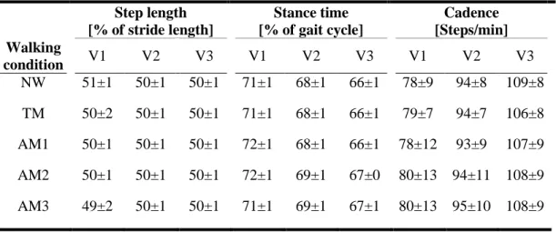
TABLE 2.1:MEAN ±SD OF SPATIO-TEMPORAL PARAMETERS CATEGORIZED BY SPEED AND WALKING MODALITY. CONDITION CODING: SLOW SPEED (V1), SPEED SELECTED ACCORDING TO DYNAMIC SIMILARITIES PRINCIPLE
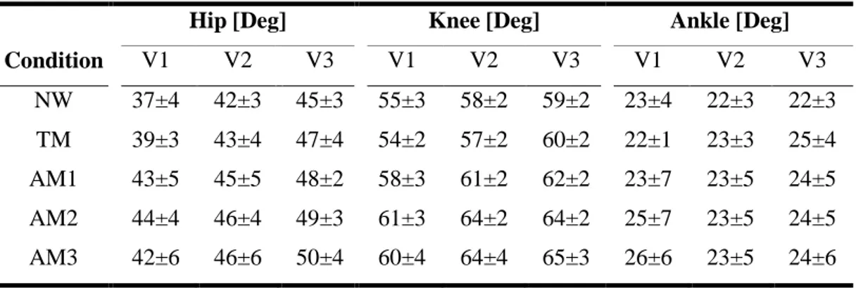
(V2), FAST SPEED (V3), NATURAL WALKING –NO APO-(NW), TRANSPARENT MODE -APO SHADOWS THE WEARER-(TM), LOW ASSISTANCE (AM1), MODERATE ASSISTANCE (AM2), HIGH ASSISTANCE (AM3). ... 23 TABLE 2.2:MEAN ±SD OF ROM CATEGORIZED BY SPEED AND WALKING MODALITY.CONDITION CODING: SLOW
SPEED (V1), SPEED SELECTED ACCORDING TO DYNAMIC SIMILARITIES PRINCIPLE (V2), FAST SPEED (V3),
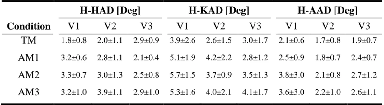
NATURAL WALKING –NO APO-(NW), TRANSPARENT MODE -APO SHADOWS THE WEARER-(TM), LOW ASSISTANCE (AM1), MODERATE ASSISTANCE (AM2), HIGH ASSISTANCE (AM3). ... 24 TABLE 2.3:MEAN ±SD OF HUMAN HIP ANGLE DEVIATION (H-HAD), HUMAN KNEE ANGLE DEVIATION (H-KAD) AND
HUMAN ANKLE ANGLE DEVIATION (H-AAD) CATEGORIZED BY SPEED AND WALKING MODALITY.CONDITION CODING: SLOW SPEED (V1), SPEED SELECTED ACCORDING TO DYNAMIC SIMILARITIES PRINCIPLE (V2), FAST SPEED (V3), TRANSPARENT MODE -APO SHADOWS THE WEARER-(TM), LOW ASSISTANCE (AM1), MODERATE ASSISTANCE (AM2), HIGH ASSISTANCE (AM3). ... 26
TABLE 2.4:MEAN ±SD OF AVERAGE INTRA-SUBJECT VARIABILITY OF HIP, KNEE AND ANKLE FLEXION-EXTENSION ANGLE CATEGORIZED BY SPEED AND WALKING MODALITY.CONDITION CODING: SLOW SPEED (V1), SPEED SELECTED ACCORDING TO DYNAMIC SIMILARITIES PRINCIPLE (V2), FAST SPEED (V3), NATURAL WALKING –NO
APO-(NW), TRANSPARENT MODE -APO SHADOWS THE WEARER-(TM), LOW ASSISTANCE (AM1),
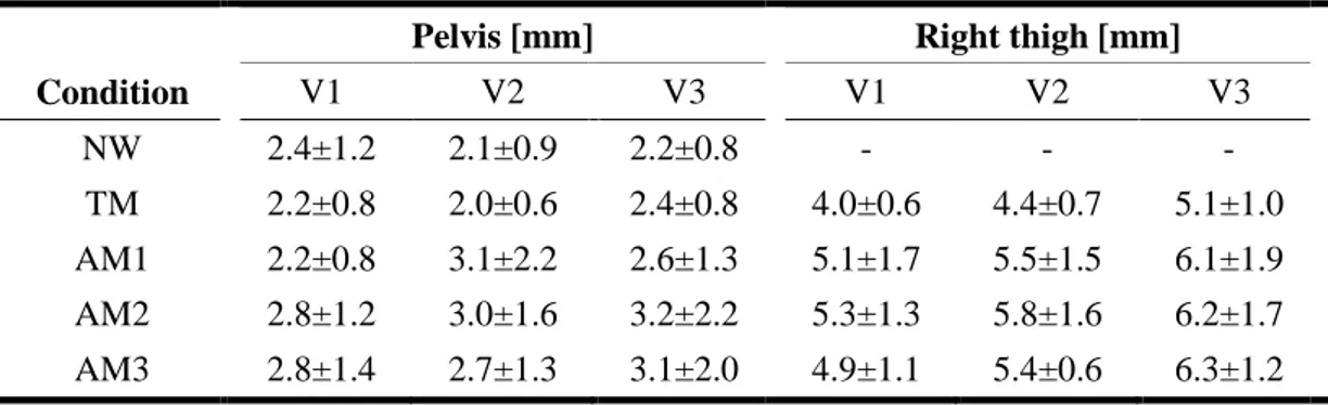
MODERATE ASSISTANCE (AM2), HIGH ASSISTANCE (AM3). ... 26 TABLE 2.5:MEAN ±SD OF PHR-ID CATEGORIZED BY SPEED AND WALKING MODALITY.CONDITION CODING: SLOW
SPEED (V1), SPEED SELECTED ACCORDING TO DYNAMIC SIMILARITIES PRINCIPLE (V2), FAST SPEED (V3),
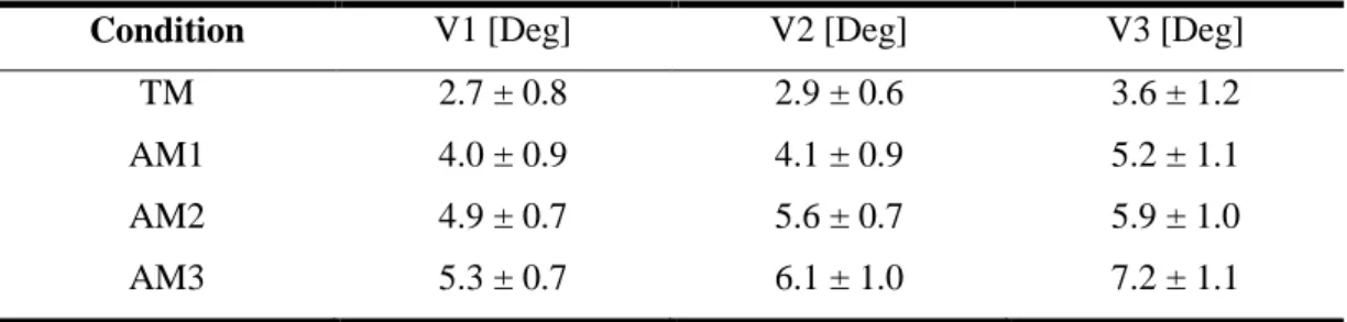
NATURAL WALKING –NO APO-(NW), TRANSPARENT MODE -APO SHADOWS THE WEARER-(TM), LOW ASSISTANCE (AM1), MODERATE ASSISTANCE (AM2), HIGH ASSISTANCE (AM3). ... 29 TABLE 2.6:MEAN ±SD OF HR-HAD CATEGORIZED BY SPEED AND WALKING MODALITY.CONDITION CODING: SLOW
List of Tables
xx
TRANSPARENT MODE -APO SHADOWS THE WEARER-(TM), LOW ASSISTANCE (AM1), MODERATE ASSISTANCE
(AM2), HIGH ASSISTANCE (AM3). ... 30 TABLE 3.1:MEAN ±SD OF SPATIO-TEMPORAL PARAMETERS CATEGORIZED BY SPEED AND WALKING MODALITY.
CONDITION CODING: SELF-SELECTED (V1), FAST SPEED (V2), NATURAL WALKING –NO APO-(NW),
TRANSPARENT MODE -APO SHADOWS THE WEARER-(TM), LOW ASSISTANCE (AM1), HIGH ASSISTANCE
(AM3). ... 51 TABLE 3.2:MEAN ±SD OF SPATIO-TEMPORAL PARAMETERS CATEGORIZED BY SPEED AND WALKING MODALITY.
CONDITION CODING: SELF-SELECTED (V1), FAST SPEED (V2), NATURAL WALKING –NO APO-(NW), TRANSPARENT MODE -APO SHADOWS THE WEARER-(TM), LOW ASSISTANCE (AM1), HIGH ASSISTANCE
(AM3). ... 52 TABLE 3.3:MEAN ±SD OF ROM IN GROUND LEVEL WALKING CATEGORIZED BY SPEED AND WALKING CONDITION:
SELF-SELECTED SPEED (V1), FAST SPEED (V2), NATURAL WALKING –NO APO-(NW), TRANSPARENT MODE -APO SHADOWS THE WEARER-(TM), LOW ASSISTANCE (AM1), HIGH ASSISTANCE (AM2). ... 57 TABLE 3.4:MEAN ±SD OF ROM IN STAIR ASCENDING CATEGORIZED BY SPEED AND WALKING CONDITION: SELF
-SELECTED SPEED (V1), FAST SPEED (V2), NATURAL WALKING –NO APO-(NW), TRANSPARENT MODE -APO
SHADOWS THE WEARER-(TM), LOW ASSISTANCE (AM1), HIGH ASSISTANCE (AM2). ... 57 TABLE 3.5:MEAN ±SD OF HUMAN HIP ANGLE DEVIATION (H-HAD), HUMAN KNEE ANGLE DEVIATION (H-KAD) AND HUMAN ANKLE ANGLE DEVIATION (H-AAD) IN GROUND LEVEL WALKING CATEGORIZED BY SPEED AND WALKING MODALITY: SELF-SELECTED SPEED (V1), FAST SPEED (V2), TRANSPARENT MODE -APO SHADOWS THE WEARER -(TM), LOW ASSISTANCE (AM1), HIGH ASSISTANCE (AM2). ... 59 TABLE 3.6:MEAN ±SD OF HUMAN HIP ANGLE DEVIATION (H-HAD), HUMAN KNEE ANGLE DEVIATION (H-KAD) AND
HUMAN ANKLE ANGLE DEVIATION (H-AAD) IN STAIR ASCENDING CATEGORIZED BY SPEED AND WALKING MODALITY: SELF-SELECTED SPEED (V1), FAST SPEED (V2), TRANSPARENT MODE -APO SHADOWS THE WEARER
-(TM), LOW ASSISTANCE (AM1), HIGH ASSISTANCE (AM2). ... 59 TABLE 3.7:MEAN ±SD OF PHR-ID IN GROUND LEVEL WALKING CATEGORIZED BY SPEED AND WALKING CONDITION:
SELF-SELECTED SPEED (V1), FAST SPEED (V2), NATURAL WALKING –NO APO-(NW), TRANSPARENT MODE -APO SHADOWS THE WEARER-(TM), LOW ASSISTANCE (AM1), HIGH ASSISTANCE (AM2). ... 62 TABLE 3.8:MEAN ±SD OF PHR-ID IN STAIR ASCENDING CATEGORIZED BY SPEED AND WALKING CONDITION: SELF
-SELECTED SPEED (V1), FAST SPEED (V2), NATURAL WALKING –NO APO-(NW), TRANSPARENT MODE -APO
SHADOWS THE WEARER-(TM), LOW ASSISTANCE (AM1), HIGH ASSISTANCE (AM2). ... 62 TABLE 3.9:MEAN ±SD OF HR-HAD IN GROUND LEVEL WALKING AND STAIR ASCENDING CATEGORIZED BY SPEED AND WALKING MODALITY: SELF-SELECTED SPEED (V1), FAST SPEED (V2), TRANSPARENT MODE -APO SHADOWS THE WEARER-(TM), LOW ASSISTANCE (AM1), HIGH ASSISTANCE (AM2). ... 66
Physical Human-Robot interaction in wearable robotics
xxi
TABLE 3.10:MEAN ±SD OF AVERAGE INTRA-SUBJECT VARIABILITY OF HIP, KNEE AND ANKLE FLEXION-EXTENSION ANGLE IN GROUND LEVEL WALKING CATEGORIZED BY SPEED AND WALKING CONDITION: SELF-SELECTED SPEED
(V1), FAST SPEED (V2), NATURAL WALKING –NO APO-(NW), TRANSPARENT MODE -APO SHADOWS THE WEARER-(TM), LOW ASSISTANCE (AM1), HIGH ASSISTANCE (AM2). ... 68 TABLE 3.11:MEAN ±SD OF AVERAGE INTRA-SUBJECT VARIABILITY OF HIP, KNEE AND ANKLE FLEXION-EXTENSION
ANGLE IN STAIR ASCENDING CATEGORIZED BY SPEED AND WALKING CONDITION: SELF-SELECTED SPEED (V1), FAST SPEED (V2), NATURAL WALKING –NO APO-(NW), TRANSPARENT MODE -APO SHADOWS THE WEARER -(TM), LOW ASSISTANCE (AM1), HIGH ASSISTANCE (AM2). ... 69
xxiii
Disambiguation
Wearable robotics is a particular branch of robotics where the interaction with the human is inherently close. As the number of applications of such devices increases improved safety standards are required. Since the concept of safety is often related to the specific application and is characterized by several attributes, in this brief section we aim at defining words frequently used in this thesis within the framework of wearable robotics.
safety: the absence of damages and injuries to the user.
reliability: the continuity of service of the robot.
availability: the readiness of service of the robot
dependability: safety, reliability and availability
comfort: the absence of pain or discomfort.
ergonomics: ergonomics, as defined by the International Ergonomics Association1, “is the scientific discipline concerned with the understanding of interactions among humans and other elements of a system, and the profession that applies theory, principles, data and methods to design in order to optimise human well-being and overall system performance.
1
1 Introduction
Modern robots are progressively making their way into non-structured environments, such as private homes, hospitals, and service areas [1]. This category of robots is often referred as “human-centered” or “human-friendly”, due to their close interaction with the human being [2]. This interaction may be categorized in two main typologies: remote interaction and proximate interaction. In the former case, the human and the robot do not share a common workspace being physically (or even temporally) separated. In the latter case, the human and the robot are co-located and a direct human machine contact may occur. A particular case of proximate interaction is found in wearable robots or exoskeletons. These devices are conceived to be worn by the user and constantly exchange a bidirectional flow of power and information in order to augment or restore human motor capabilities.
First studies on wearable robots date back to 1960s in the United States [3] and in the former Yugoslavia [4] as military and medical applications respectively [4]. Today, after almost 80 years of research, exoskeletons find application in military, healthcare, service, industrial and space sectors, not only as research platforms or prototypes but as fully developed products. Even though huge advancements have been carried out in the development of these devices, several issues such as safety and reliability are still open and require researchers’ attention. Most problems in the use of wearable robots are related to the close interaction with the wearer. In the rest of this chapter we will explore: (i) the problem of interacting with a wearable robot; (ii) the solutions proposed in literature for an ergonomic interaction with the user; (iii) the state of the art of ergonomic evaluation methodologies; and (iv) a novel framework for the ergonomic assessment of wearable robots.
Introduction
2
1.1 Physical Human-Robot interaction in wearable robotics
The interaction between a wearable robot and the user occurs mainly at two levels, namely cognitive and physical [5]. Even though the cognitive human-robot interface is of paramount importance to properly manage the exchange of information between the robot and the user, we will focus our attention on the physical human-robot interface (pHRI). One of the most peculiar features of a wearable robot is its intrinsic capability of interacting closely with the user. Indeed, exoskeletons can exchange forces and motion with the wearer by activating each joint separately. While this possibility offers great flexibility and several fields of application to wearable robots, as a drawback, it poses constrains to their design.
Due to the close interaction between a wearable robot and the user, their reciprocal motion and application of forces must be accurately controlled and coordinated. Otherwise, severe injuries may occur to the wearer. In order to address this topic, the user have to be included in the exoskeleton design process since the early stages. Hence, the design of robot mechanical structure, actuation units, sensors and control architecture must take into account the interaction with humans. To this end the wearable robot must be endowed with the following features [7]:
Safety: during operation the robot must respect the natural kinematics of the wearer and be compliant with him. For instance, non-physiological movements, such as excessive excursions which may over-extend the human articulations must be avoided.
Application of loads to humans: typically the transmission of forces between the robot and the user’s musculoskeletal system occurs through soft tissues. This poses the issue of defining the maximum intensity of the force, the geometry of the interaction surface, the area of interaction.
Ergonomics and comfort: wearable robots should not only guarantee a safe operation, but also address the intra- and inter-subject variability. This requires the human and robotic joint axes to be closely aligned even when no torque is delivered to the wearer (namely, the kinematic structure must be compliant to user biomechanics even before the actuation is embedded in the device).
Physical Human-Robot interaction in wearable robotics
3 Misalignments may cause parasitic forces to the user, leading to pressure sores, stumbling or even damage to the biological joints.
Weight and encumbrance: Especially for wearable robots intended for supporting daily-living activities, lightness and low encumbrance are critical features to be achieved.
Ease of use: Wearable robots must be designed to be easily donned and doffed by different users, also tuning rapidly the links lengths if necessary.
The first step to fulfil these requirements is the design of a proper mechanical structure, which complies with the user kinematics. Ideally, the human-robot kinematic coupling allows the user to span the whole physiological workspace without the exoskeleton being perceived as a constrain. To achieve this goal, the human-robot joint axes should be perfectly aligned during movement. Unfortunately, the exact location of human joint axes is not easily identified due to several factors.
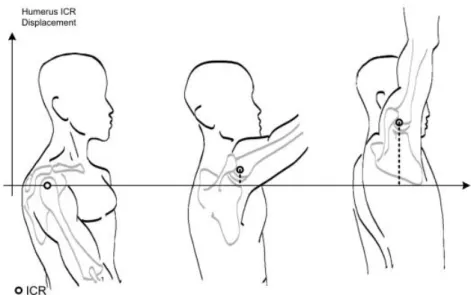
First of all the anthropometry of different subjects may largely vary, i.e.: limbs length, weight and shapes, distance between joint axes and joint axes orientation. Secondly, the instantaneous center of rotation of biological joints does change its location during movement along the work space (Figure 1.1).
Figure 1.1: Translation of the instantaneous centre of rotation (ICR) of the glenohumeral shoulder joint during shoulder abduction. This shows how human joint centers of rotation are non-stationary. An ergonomic exoskeleton will have to cope with such alterations of
Introduction
4 the human anatomical structure during movement. (Adapted from [7], © 2008 Wiley & Sons, with permission from Wiley & Sons).
All these challenges make the design of wearable robots adaptable to a large range of users difficult. Especially if we consider that all human limb links are covered with soft tissues (muscles, fat, skin, cartilage…) which not only hide subject’s skeleton but also have different biomechanical properties from subject to subject.
In conclusion, causes of kinematic incompatibility may be gathered into two groups: (i) macro-misalignments and (ii) micro-misalignments [9]. Macro-misalignments between robotic and human joint axes are due to an oversimplification of exoskeletal joints. In other words, the exoskeleton joint has less degrees of freedom than the corresponding biological joint. Micro-misalignments are more difficult to be avoided a-priori. Indeed, they occur even when the number of degrees of freedom of exoskeleton joints match properly the human one. This is due to non-perfectly aligned joint axes of rotation between human and robot. Variability of instantaneous center of rotation during movement and variability among different subjects cause the human joint axes location to be not predictable. Furthermore, even if by chance the robotic joints are aligned correctly, micro-misalignments may still occur due to soft tissue compression or slippage of the exoskeleton over the skin during movement.
1.2 Ergonomic kinematic design of wearable robots
At the best of our knowledge, one of the first authors who systematically investigated ergonomics in the field of wearable robotics was Andrè Schiele. In their work, Schiele and his colleagues [9] pointed out that it is desirable that wearable robots must be capable of (i) training the whole functional workspace of human limbs; (ii) inducing exact ergonomic movements in the wearer by activating joint by joint; and (iii) avoiding discomfort or safety hazards for the user during movement.
To achieve the above features, according to Schiele, the wearable robot kinematic structure must not copy the one of the human limb of interest, meaning that the number and location of robotic joints must not be exactly equal to the human ones. On the contrary, the robotic kinematic chain must be endowed with a set of pDoFs, which prevent the creation of joint axes misalignment and the consequent generation of parasitic
Ergonomic kinematic design of wearable robots
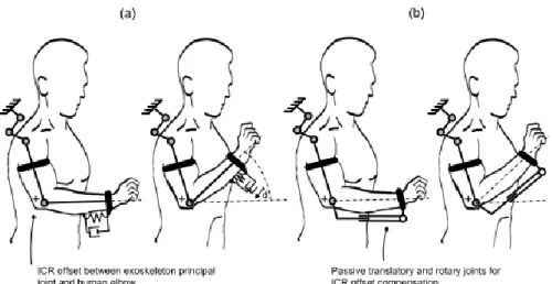
5 forces, if axes misalignments are present. When considering the 2D example of elbow flexion/extension in Figure 1.2 (a), a robotic kinematic chain consisting in a simple hinge joint may generate parasitic forces limiting the user range of motion and creating discomfort or possibly pain. The addition of translational and rotational pDoFs as in Figure 1.2 (b) compensates for joint axes misalignments and solve the above issues.
Figure 1.2: Illustration of the creation of interaction force as a consequence from joint misalignments between exoskeleton and human limb (a). During motion, the exoskeleton slides on the human limb. If passive joints are added into the structure those forces are not created (b), the joints compensate for the slipping of the device. (Adapted from [7], © 2008 Wiley & Sons, with permission from Wiley & Sons).
Another author that largely contributed to the creation of guidelines for an ergonomic design of wearable robots is Arnold Stienen. In order to automatically align human and robotic axes, he proposed to decouple joint rotations from joint translations [10]. The possibility of the exoskeleton axes to freely translate -according to the constrains offered by the kinematics of the connected biological limb- allows these axes to self-align to biological axes. Even though this procedure increases mechanical complexity and overall inertia, it may reduce setup times and harmful parasitic forces onto the human articulations. Indeed, whenever a misalignment generates a translational reaction force, the linkage will slide until a new zero-force position is reached (Figure 1.3).
Introduction
6 Figure 1.3: Self-alignment for exoskeletons axes in a planer view. (a) The effects of a single misaligned axis at the shoulder. Due to exoskeleton torque Tex, the arm and
exoskeleton axes rotate an angle α. If these axes are misaligned, the human joint has to translate relative to the exoskeleton axis. If the axes are fixed, this movement creates a residual shoulder force Fsh , which is dependent on the stiffness of skin and bone, and an
equal exoskeleton reaction force Fex . (b) Translating exoskeleton axes prevents these
misalignment forces. If a misalignment causes a force Fex , the exoskeleton translates
until this force is gone. Torques can be applied to the limb from the rotational-stiff linkage mechanism. The effects are the same in 3-D by adding the two other rotational axes requiring only the one final linear axis. (Adapted from [10], © 2009 IEEE, with permission from IEEE)
A different approach to overcome kinematic incompatibility was proposed by Jarassé et al. [11], who faced the problem of interfacing two similar kinematic chains through multiple passive mechanisms from a more general perspective. In particular he developed a construction criterion to systematically determine all the possible configurations of passive degrees of freedom in different fixation mechanisms, also providing formal proofs of global isostaticity. Adding pDoFs in sequence is a typical principle used in mechanism theory to reduce the degree of iperstaticity. The main advancement brought by Jarassè was to extend its application to the general case of 3D mechanisms for wearable robots.
A novel framework for the evaluation of the ergonomics of a wearable robot
7
1.3 A novel framework for the evaluation of the ergonomics of a
wearable robot
In the last decade, ergonomic design criteria were adopted to develop exoskeletons with several applications, such as tele-manipulation [12], gait rehabilitation [13]-[15], assistance of patients with mild gait deficiencies [16]-[17] or paralyzed [19]-[21]. The increasing number of developed prototypes or products underlines the need for an effective and efficient systematic evaluation of their performances, especially in terms of ergonomics and comfort.
To the best of our knowledge, the first study in this direction was conducted by Andrè Schiele in [23]. He quantified the effect of joint misalignments measuring the magnitudes of interaction forces and related subjective perception and objective performance metrics to (i) the interaction pressure between exoskeleton and the human limb and to (ii) the presence or absence of kinematic compensatory joints, such as pDoFs, in the mechanical structure of the exoskeleton.
This study, not only proved the efficacy of pDoF systems to reduce parasitic interaction forces, but also proposed a useful metrics for the evaluation of wearable robots ergonomics. Thanks to this metrics it was possible to identify the optimal interaction pressure for the tested (arm) exoskeleton. Nevertheless, the major limitation of this study –in terms of ergonomic assessment– is the need for a design modification of the robot (due to the addition of sensors), which has a twofold drawback: (i) it may alter the ergonomics of the tested exoskeleton and (ii) make this methodology difficult to be extended to other platforms.
Another study about ergonomics of exoskeletons was proposed by Marco Cempini and his colleagues [22]. In their work they pointed the attention on the stability of the human-exoskeleton coupling. As a test bed they used a thumb-finger human-exoskeleton endowed with pDOFs at the metacarpal-phalangeal joint. As a metrics to assess the actual stability of the interaction, they measured the relative displacements between corresponding human and robot segments, under the assumption that no displacement is ideally possible when it is optimal the kinematics coupling between the user and the robot. However this study can be considered as an early (still incomplete) attempt to make an analysis of the ergonomics
Introduction
8 of human-exoskeleton interaction, mostly for two reasons. First, it was not possible to actually assess the loading effect deriving from wearing the device (i.e., comparing human kinematics with/without the exoskeleton); this was not possible mostly because was not easy to measure the hand kinematics while wearing the device for the inherent difficulty to place markers on the human hand segments. Second, since the device was not collaborative (i.e., the robot joints were a source of velocity and no assist-as-needed control paradigms were possible) it was not possible to compare the kinematics of the human hand under two different conditions, namely: i) the device is transparent to the user movement ability, and ii) the device applies a pre-defined assistive torque.
In this work, grounded on the experience reported in the state of the art, we proposed a more complete methodology to assess the ergonomics in exoskeletons. In particular, by taking as a test bed a “truly” collaborative lower-limb exoskeleton for hip assistance, we aimed at progressing the state of the part by proposing a set of experiments where we assessed ergonomics against three main factors at the same time: i) the loading effect on the human gait deriving from wearing the device acting as a “transparent” orthosis, i.e., not providing any assistance and not hindering the human movement, ii) the stability of the human-robot interaction, and iii) the discrepancy between the human and robot joint kinematics when the exoskeleton is actually providing assistance to the human gait. These three factors led to the definition of three quantitative indicators:
The first indicator captures the quality of the kinematic coupling, namely the capability of the device to not alter natural kinematics of a healthy wearer during a task. Indeed, any change in the physiological patterns of joint angles during walking are perceived as negative or hindering by the human user and it can also lead to safety hazards in extreme cases.
The second indicator measures the stability of the interaction at the physical interface level, namely the relative displacements between the orthotic shells of the robot and corresponding limbs of the wearer. The magnitude of relative displacements is directly related to the comfort of the device. Indeed, relative displacements at the physical interface level may cause painful sores or skin irritation.
References
9
The third indicator measures the human-robot kinematic discrepancy during operation, namely the difference between robotic and human joint angles. As discussed in the following chapters, this indicator together with the second one may provide important information, such as the presence of major or minor joint axes misalignment.
As a test bed we used an active pelvis orthosis (APO) conceived to assist hip flexion extension in subjects affected by gait mild impairments2. The APO was designed to be a collaborative machine and –as described with more details in section 1.2- it is endowed with a pDOFs for an optimal human-robot joint axis self-alignment.
In the next chapter 2 we analyze the ergonomic performance of the APO in the case of healthy subjects performing tasks of treadmill walk. In the chapter 3 we report the results of an experiment where the proposed approach is validated in a more ecological scenario where healthy subjects perform tasks of over-ground walking and stair ascending.
1.4 References
[1] O.Khatib, O. Brock, K.C.Chang, D.Ruspini, L.Sentis, S.Viji. Human-Centered Robotics and Interactive Haptic Simulation.
[2] Robert Riener, Dr-Ing; Lars Lünenburger, Dr rer nat;Gery Colombo, PhD. Human-centered robotics applied to gait training and assessment. Journal of rehabilitation Research & Development. 2006: Vol 43(5): 679-694.
[3] R. S. Mosher, Handiman to Hardiman. SAE Technical paper. Tech. Rep. 1967. [4] M. Vukobratovic, B. Borovac, D. Surla and D. Stokic. Bipedal locomotion. Springer-Verlag. 1990:349.
[5] Pons JL. Rehabilitation exoskeletal robotics. IEEE Engineering in Medicine and Biology Magazine. 2010;29(3), 57-63.
2 The APO has been developed by The BioRobotics Institute within the framework of two
projects, namely the EU FP7 CYBERLEGs Project, and the IUVO project funded by Fondazione Pisa.
Introduction
10 [6] A. M. Dollar and H. Herr. Lower extremity exoskeletons and active orthoses: challenges and state-of-the-art. Robotics, IEEE Transaction on, vol. 24, no 1, pp. 144-158,2008
[7] J.L. Pons, Wearable Robots: Biomecatronic Exoskeletons, Wiley & Sons, Ltd, ISBN 978-0-470-51294-4, cap. 8, 2008.
[8] Schiele A, Hirzinger G. A new generation of ergonomic exoskeletons - The high-performance X-Arm-2 for space robotics telepresence. In IEEE International Conference on Intelligent Robots and Systems. 2011; doi: 10.1109/IROS.2011.6094868.
[9] Schiele A, et al. Kinematic design to improve ergonomics in human machine interaction. IEEE Transaction on Neural System and Rehabilitation Engineering. 2006; doi: 10.1109/TNSRE.2006.881565.
[10] Stienen A, Hekman E, Van Der Helm F, Van Der Kooij H. Self-aligning exoskeleton axes through decoupling of joint rotations and translations. IEEE Transactions on Robotics. 2009; doi: 10.1109/TRO.2009.2019147.
[11] N. Jarrasse and G. Morel, "Connecting a Human Limb to an Exoskeleton," in
IEEE Transactions on Robotics, vol. 28, no. 3, pp. 697-709, June 2012. doi:
10.1109/TRO.2011.2178151
[12] Schiele, André; Visentin, Gianfranco. The ESA human arm exoskeleton for space robotics telepresence. (iSAIRAS) 7th International Symposium on Artificial Intelligence. Robotics and Automation in Space". 2003
[13] Colombo, G., Joerg, M., Schreier, R., & Dietz, V. (2000). Treadmill training of paraplegic patients using a robotic orthosis. Journal of rehabilitation research and development, 37(6), 693.
[14] Jezernik, S., Colombo, G., Keller, T., Frueh, H., & Morari, M. (2003). Robotic orthosis lokomat: A rehabilitation and research tool. Neuromodulation: Technology at the neural interface, 6(2), 108-115.
[15] Banala, S. K., Agrawal, S. K., & Scholz, J. P. (2007, June). Active Leg Exoskeleton (ALEX) for gait rehabilitation of motor-impaired patients. In Rehabilitation Robotics, 2007. ICORR 2007. IEEE 10th International Conference on (pp. 401-407). IEEE.
References
11 [16] Giovacchini F, Vannetti F, Fantozzi M, Cempini M, Cortese M, Parri A, Yan T, Lefeber D, Vitiello N. A light-weight active orthosis for hip movement assistance. Robotics and Autonomous Systems. 2015; doi: doi:10.1016/j.robot.2014.08.015.
[17] Ekso Bionics. Available at: http://intl.eksobionics.com/ [accessed 25.03.17]. [18] Pransky J. The Pransky interview: Russ Angold, co-founder and president of Ekso Labs. Industrial Robot: An Int J 2014;41:329 e 34.
[19] Zwecker M, Dudkiewicz I, Bloch A, Esquenazi A. Safety and tolerance of the ReWalk exoskeleton suit for ambulation by people with complete spinal cord injury: a pilot study. J Spinal Cord Med 2012;35:96 e 101.
[20] Talaty M, Esquenazi A, Briceno JE. Differentiating ability in users of the ReWalkTM powered exoskeleton: an analysis of walking kinematics. IEEE International Conference on Rehabilitation Robotics (ICORR). Washington USA: IEEE; Seattle; 2013. p. 1 e 5.
[21] CADTH. ReWalk: robotic exoskeletons for spinal cord injury. Available at:
https://www.cadth.ca/rewalk-robotic-exoskeletons-spinal-cord-injury [accessed
25.03.17].
[22] Cempini M, Marzegan A, Rabuffetti M, Cortese M, Vitiello N, Ferrarin M. Analysis of relative displacement between the HX wearable robotic exoskeleton and the user’s hand. Journal of NeuroEngineering and Rehabilitation. 2014;doi: 10.1186/1743-0003-11-147.
[23] Schiele A, van der Helm FC. Influence of attachment pressure and kinematic configuration on pHRI with wearable robots. Applied Bionics and Biomechanics. 2009;6(2), 157-173.
[24] Cempini M, De Rossi SMM, Lenzi T, Mario C, Giovacchini F, Vitiello N, Carrozza MC: Kinematics and design of a portable and wearable exoskeleton or hand rehabilitation. Proc IEEE Int Conf Rehabil RobotICORR 2013, 2013:1–6.
[25] Cempini M, Cortese M, Vitiello N: A powered finger-thumb wearable hand exoskeleton with self-aligning joint axes. IEEE/ASME Trans Mechatronics 2014. DOI:10:1109/TMECH.2014.2315528
13
2 Physical human-robot interaction of an
active pelvis orthosis: toward ergonomic
assessment of wearable robots
32.1 Introduction
In the field of human-centered robotics, exoskeletons are becoming relevant for addressing needs in the healthcare and industrial domains [1]-[2] , both as tools for rehabilitation treatment and clinical assessment [3]-[4] and for augmented reality applications (haptics [5] or augmentation [6]). Despite the increasing interest and number of developed prototypes and commercial systems, the design of exoskeletons still has many open issues, such as those related to the development of the physical human-robot (HR) interface. Owing to their close interaction with the user, safety and ergonomics are critical features that heavily influence the functionality and the dependability of a wearable robot (WR) [7]. In general, these devices are designed to generate and transfer mechanical power to human joints: therefore, optimal kinematic coupling is required between the corresponding human and robot rotation axes [8].
Misalignment between the human and robot joint axes can cause undesired forces that overload human articulations, thus resulting in an uncomfortable or even painful interaction with the robot [9]. Undesired forces originating from joint axis misalignments
3d’Elia N, Vannetti F, Cempini M, Pasquini G, Parri A, Rabuffetti M, Ferrarin M, Molino Lova R,
Vitiello N. Physical human-robot interaction of an active pelvis orthosis: toward ergonomic assessment of wearable robots. Journal of NeuroEngineering and Rehabilitation. 2017; 14:29. DOI: 10.1186/s12984-017-0237-y.
Physical human-robot interaction of an active pelvis orthosis: toward ergonomic assessment of wearable robots
14 (JAxM) can also lead the orthotic shells of the exoskeleton to slide along the human limb segments, leading to unreliable assistive torque transmission [10] and possible skin inflammation or even sores.
Unfortunately, the achievement of adequate human-robot joint axis alignment is not an easy condition to be fulfilled for two main reasons. First, it is not possible to know the exact location of the anatomical joint rotation axis without complex imaging techniques. Second, human articulations are not ideal rotational or spherical mechanical couplings; rather, they have more complex subject-dependent geometries that make the rotation axes fluctuate along the range of movement (ROM) [10].
As a consequence of the above considerations, most exoskeletons are provided with regulation mechanisms and/or passive degrees of freedom (pDoFs), in accordance with the guidelines proposed in [11]. In his work, Stienen and colleagues explained that it is possible to unload human articulations from undesired translational forces by decoupling joint rotations and translations by adding a certain number of passive DoFs to exoskeleton joints. Examples of WRs for both upper- and lower-limb assistance/rehabilitation equipped with passive DoFs have been reported in [11],[12],[13],[14]. A more recent study also introduced a theoretical framework to identify the constructive parameters of the chain of passive DoFs that are necessary to cope with human flexion-extension articulations [7].
However, the introduction of passive DoFs into the design of a WR is not free of drawbacks; the tradeoff between the degrees of laxity [15] and the system complexity may affect the overall human-robot kinematics coupling [7]. On the one hand, by increasing the degree of laxity of the powered joints, there is a risk of increasing the overall inertia and friction of the moving parts. On the other hand, a lack of adequate laxity partially affects the human-robot joint axis self-alignment and thus hinders the spontaneous movement of the user. As a consequence, in the development and design of an exoskeleton, the assessment of its kinematic compatibility with user biomechanics is of paramount importance.
Many exoskeletons constitute the current state of the art; the variety of mechatronics designs, control systems, and human-machine interfaces are due to differences in the
Introduction
15 targeted users and expected usage. An extensive review of WRs, their design methodologies, and control strategies can be found in [16],[17],[18].
A category of powered WRs that is gaining an increasing level of attention is that of exoskeletons addressing the needs of people with mild gait disturbances (e.g., gait post-stroke hemiparesis, unilateral lower-limb amputation, senile gait, etc.), who may benefit from the use of light-weight assistive WRs to recover more stable, efficient, and independent locomotion [17],[19],[20],[21].
At The BioRobotics Institute (Scuola Superiore Sant’Anna, Pisa, Italy), we have recently developed a revised version of the active pelvis orthosis (APO) presented in [22], a wearable exoskeleton aimed at improving the gait energy efficiency of users affected by mild impairments through the assistance of hip flexion-extension (f/e) [23]. The main advancement of the new device over the previous version is the introduction of a chain of passive DoFs that allows the human f/e axis to align with that of the robot and simultaneously gives the user free hip abduction/adduction (a/a) and internal/external (i/e) rotations. The APO is interfaced with the wearer through tailored thermoplastic orthotic shells (namely, cuffs) to ensure maximum comfort.
The adopted design criterion is in line with the approaches proposed by several authors [7],[10],[11] for the development of exoskeletons that interact smoothly with the wearer. Nevertheless, to the best of our knowledge, no ergonomics evaluation methodology has been proposed in the literature and no clear definition of WR ergonomics has been given. Hereafter, we refer to ergonomics as the capability (of a WR) to smoothly interact with the user along the whole work space by “optimizing human well-being and overall system performance” [24] and without hindering natural kinematics or causing discomfort and/or injury.
The direct evaluation of ergonomics from ultimate determinants, such as comfort and risk of injury, may be performed only after long-term use. For this reason, the possibility to define the “level of ergonomics” from easily obtainable indirect measures that are related to ergonomics is attractive.
In this work, we carried out an experimental validation with healthy volunteers with the objective of assessing the quality of the user-APO physical interaction with particular
Physical human-robot interaction of an active pelvis orthosis: toward ergonomic assessment of wearable robots
16 reference to the chain of passive DoFs and the relative shifts between the APO frame and the human body at the physical interfacing areas. Using this specific device as an example, we discuss the specific design of a WR and propose a set of indicators that could be relevant for its evaluation in terms of ergonomics.
First, we analyzed the alteration of lower-limb joint kinematics by comparing the condition in which users walked without wearing the APO and all experimental conditions when they wore it. Human kinematics was recorded by means of an optoelectronic motion capture system. Secondly, we analyzed the stability of the physical interaction between the users and the APO by measuring: (i) the displacements between the APO orthotic cuffs and the wearer’s corresponding body segments, and (ii) the kinematic discrepancy between the APO and the wearer's hip f/e joint angle.
Besides the ease of measurement, the following hypotheses form the rationale behind the choice of these variables: (i) deviation from natural kinematics is recognized as a negative effect on the wearer; (ii) relative displacements at the HR interface may cause skin irritations or sores and therefore discomfort or injuries; (iii) HR kinematic discrepancy together with relative displacements at the interface may reveal possible JAxM, which are the cause of residual forces onto articulations and possibly pain or injuries after prolonged use.
We carried out this study being aware that: (i) optoelectronic systems have been widely used to measure human gait kinematics [25], also during orthosis-assisted locomotion [26], [27], and (ii) the feasibility of measuring displacements in the order of millimeters (in the range 3.2–6.7 mm) using a video-based motion capture system, such as that used in the present application, has been already demonstrated [28],[29].
2.2 Methods
2.2.1 Participants
Five healthy adults (74.4 ± 6.8 kg, 1.73 ± 0.07 m, 29.2 ± 6.3 years old) were enrolled for the study. All participants signed an informed consent before starting the experimental sessions. The research procedures were conducted at the premises of Fondazione Don
Methods
17 Carlo Gnocchi (Firenze, Italy) in accordance with the Declaration of Helsinki, after the approval of the local Ethical Committee.
2.2.2 Active Pelvis Orthosis
The APO is a bilateral powered exoskeleton, and it is constituted of three main subsystems: the mechanical structure, the actuation units, and the control system. In the following, we provide a description that summarizes its main features.
The mechanical structure of the APO is symmetrical with respect to the sagittal plane (Figure 2.1). Each side of the robot is composed of two main subsystems, namely, the chain of passive DoFs and the transmission means that transfer the assistive torque from the actuation unit to the human hip articulation.
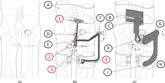
Figure 2.1: a) Human skeleton covered by soft tissues. b) Human body with wearable robotic chain schematic: (1) passive translational DoF, (2) abduction/adduction rotation passive DoF, (3) internal/external rotation passive DoF, (4) rotation passive DoF, (A) pelvis cuff, (D) internal/external rotation joint, (E) abduction/adduction joint, (F) flexion/extension joint. c) Human body coupled with exoskeleton: (B) carbon-fiber plate, (C) sliding carbon-fiber plate, (G) lateral extensible arm, (H) thigh linkage, (I) thigh cuff. For the sake of clarity, only the right part of the bilateral APO is represented.
Each chain of passive DoFs originates from a main posterior carbon fiber plate (i.e., the frame of the chain of passive DoFs), which connects the exoskeleton to the wearer’s trunk by means of an orthotic cuff. Another carbon-fiber plate can slide horizontally against the frame by means of a passive translational DoF (axis number 1 in Figure 2.1). The sliding
Physical human-robot interaction of an active pelvis orthosis: toward ergonomic assessment of wearable robots
18 plate houses two passive rotational DoFs, whose axes of rotation (namely, axes number 2 and 3 in Figure 2.1) are orthogonal and cross each other at point P. Thanks to the combined action of the translational passive DoF, the rotation axis number 2 can be aligned with the human hip a/a axis. The range of motion of axis number 2, and, consequently, that of the user’s a/a, is restricted to −15° to +20° via mechanical end stops. The concomitant movement of the translational passive DoF and that of axis number 3 allow the user to also have a free hip i/e. The ROM of axis number 3 is restricted to –10° to +10° by mechanical end stops. This kinematic chain of passive DoFs connects the main carbon fiber plate to a lateral arm, also made of carbon fiber. The distance between the left and right lateral arms on the frontal plane can be manually adjusted to fit the width of the wearer’s pelvis. Each lateral arm is made of two telescopic shells that can slide against each other in order to maximally align the human and robot f/e axes in the sagittal plane by manually tuning their lengths. A thigh linkage rotates around the f/e axis and couples with the wearer’s thigh via an orthotic shell. Finally, an additional rotational DoF is inserted between each link and the cuff (axis number 4 in Figure 2.1); this allows the alignment of the cuff and thigh longitudinal axes, thus providing considerable stability during movement. The APO kinematic chain design is patent pending [30].
The transmission system connects the actuation unit placed on the rear part of the lateral arm to a driven pulley placed coaxially with the hip f/e axis by means of a steel cable (U8191517, Carl Stahl®GmbH, Suessen, Germany) in a capstan configuration. The stiffness of the cable is 250 N/mm, equivalent to a torsional stiffness at the hip joint of 756 Nm/rad. The rotation axis of the actuation unit is parallel to the hip f/e axis.
Each actuation unit is a series elastic actuator (SEA). Each SEA is composed of a 70 W DC motor (EC60, Maxon Motor®, Sachseln, Switzerland), a 100:1 harmonic drive (CPL-14A-100-2A, Harmonic Drive®, Limburg, Germany), and a custom torsional spring (patent pending) having a stiffness of 100 Nm/rad. Two absolute 17-bit Rotary Electric Encoder™ units (DS-37 and DS-25 Netzer Precision Motion Sensors Ltd, Misgav, Israel) measure the spring deformation and the actual hip joint angle, respectively.
The control system has a hierarchical structure made of a low- and a high-level layer. For the control system, we adopted the same control architecture as that described in [22];