Regular Article
Structural pattern and functional correlations of the long bone diaphyses intracortical
vascular system
Investigation carried out with China ink perfusion and multiplanar analysis in the
rabbit femur
Ugo E. Pazzaglia
a,⁎
, Terenzio Congiu
b,⁎
, Marcella Marchese
a, Guido Zarattini
aaClinica Ortopedica dell'Università di Brescia, Spedali Civili di Brescia, 25123 Brescia, Italy b
Dipartimento di Morfologia Umana, Università dell'Insubria, Varese, Italy
a b s t r a c t
a r t i c l e i n f o
Article history:
Accepted 7 February 2011 Available online 12 February 2011
The intracortical vessel system of the rabbit femur has been studied after perfusion of the vascular tree with a water solution of dye (China ink) with multiplanar analysis. This method utilizes the full depth offield of the microscope objectives focusing different planes of the thick cortex. The microscopic observation even if restricted to a limited volume of cortex allowed to differentiate true 3-D nodes (54.5%) from the superimposition of vessels lying on different planes. The network model with elongated meshes preferentially oriented along the longitudinal axis of the diaphysis in his static configuration is not very different from the vascular anatomy depicted in the 2-D traditional models; however, the semi-quantitative morphometric analysis applied to the former supported the notion of a multidirectional microvascular network allowing change offlow according to the functional requirements. Other peculiar aspects not previously reported were cutting cone loops, blind-end and short-radius-bent vessels, and button-holesfigures. The network design and node distribution were consistent with the straight trajectory of the secondary remodeling, with the proximal-to-distal and distal-to-proximal advancement directions of the cutting cones and with two main modes of node formation, namely bifurcation of the cutting cone and interception with pre-existing canals. The general organization of the network and its uninterrupted transformation during bone modeling and remodeling suggested a substantial plasticity of the intracortical vascular system capable to adapt itself to the changeable haemodynamic conditions.
© 2011 Elsevier Inc. All rights reserved.
Introduction
The vascular supply of long bones has been extensively indagated with angio/microangiographic techniques and flussimetric techni-ques (Morgan, 1959; Trias and Fery, 1979; Rhinelander et al., 1979; Lopez-Curto et al., 1980; Bridgeman and Brookes, 1966; Brookes and Revell, 1998; Nelson et al., 1960; Hert and Hladíková, 1961; Kelly, 1968; Kelly and James, 1968) for the obvious clinical interest. It showed a similar general scheme in all mammals with a main arterial supply from the nutrient vessels of the diaphysis and from the peripheral metaphyseal arteries which support the blood circulation of the marrow and of a large part of the cortical bone. A supplementary vascular supply to the diaphysis is represented by the peripheral network of periosteal vessels, whose distribution is believed to be limited to the most external layers of the cortex
(Brookes and Revell, 1998). The vessels of the epiphyses are completely independent from the latter as long as the growth plate cartilage is present, but also after its closure they maintain a certain degree of structural autonomy, deriving their main vascular supply from the metaphyseal arteries (Rogers and Gladstone, 1950).
The intracortical vessel network, which is a part of the general system, is much less known because the methods of study currently used for soft tissues are hindered by the calcified, hard matrix where the vessels are embedded within. However due to this particular situation there is the possibility to infer data on the intracortical blood flow dynamics from the modeling/remodeling process which characterizes the development of the bone through-out the life span.
The actual knowledge of the intracortical canal system architec-ture is derived from 3-D reconstructions of the network of tunnels wherein the vessels run (Cohen and Harris, 1958; Mohsin et al., 2002; Stout et al., 1999, Cooper et al., 2003, Cooper et al., 2006), but limited data can be attained on the dynamics of the system.
Injecting the rabbit femural cortex with water-soluble dye (China ink) and employing the technique of multiplanar analysis
⁎ Corresponding authors.
E-mail addresses:[email protected](U.E. Pazzaglia),
[email protected](T. Congiu).
0026-2862/$– see front matter © 2011 Elsevier Inc. All rights reserved. doi:10.1016/j.mvr.2011.02.001
Contents lists available atScienceDirect
Microvascular Research
(Pazzaglia et al., 2008) we could produce a direct imaging of the network with a 3-D resolution within different layers of the cortex. The study can provide an“anatomic” baseline for understanding the bloodflow physiology of the long bones, supporting the notion of a multidirectional microvascular cortical network allowing change of flow according to functional requirement.
Materials and methods
The study was carried out on the femurs of six male, new Zealand white rabbits (Charles River Laboratories Italia, Calco (BG), Italy) mean weight 3.2 kg, and about 8 months of age. Rabbits of this age have a slowed longitudinal growth, but the growth plate cartilages are still open. The implications for this type of study are that there are no straight connections between epiphyseal and metaphyseal vessels.
Care and use of experimental animals was consistent with procedures and regulations of the Italian Health Ministry. To inject the vascular tree of the lower limbs the rabbits were anaesthetized with ketamine cloridrate (Imagel) and xylazine (Rompum); the aorta and the cava vein were exposed through a midline abdominal incision and a 1.5 mm catheter was inserted in the aorta between the diaphragm and the origin of the arteries to the kidneys with a direction from proximal to distal. The artery was then tightly ligated with two knots around the catheter and the rabbit was killed with a further overdose of the anaesthetic just before to start the perfusion of the vascular tree. Each rabbit was injected with the same volume (300 ml) of China ink water solution (for 100 ml: 60%, original concentrated solution furnished by the dealer (Pelikan, Milan, Italy), 40% distilled water). The amount of China ink injected corresponded to 56.25 ml/kg. A 300 ml hand syringe was used reaching a pressure of 150–200 mm of mercury in 5 s. The cava vein has been previously clamped with a forceps because a high pressure in the extracortical vascular tree was a necessary condition to balance the difference of the resistance to perfusion between extracortical and intracortical vascular tree. This manipulation produces a dilatation of the
Fig. 1. Diagram illustrating how the rabbit femurs were cut, the processing and orientation of the specimens. The red line corresponds to the longitudinal axis of the diaphysis, and the vector D is oriented toward the distal metaphysis.
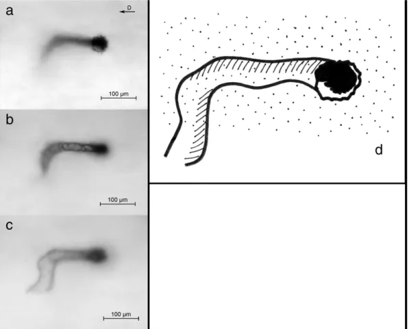
Fig. 2. Multiplanar analysis of injected vessels corresponding to periosteal surface level: three focal planes are illustrated—the first corresponding to the plane of the vessels point of entrance inside the cortex (a), the second and the third at deeper levels (b and c). The scheme shows the trajectory of the vessel (d). [The vector in the right top corner indicates the longitudinal axis of the diaphysis toward the distal metaphysis. Bar = 100μm.]
extracortical lower limbs capillary and veins network, but without haemorrhage. A satisfactory injection of the intracortical vessels can be obtained when the external resistance of the system equals the intracortical. The pressure within the intracortical system was not increased and the capillaries were not dilated. Since the study was based on the morphology of the intracortical vascular system, no limitation was supposed to have been introduced by these manipulations. The study was carried out on the femoral diaphyses, separated with two transverse cuts: the first below the great trochanter, the second proximal to the distal growth plate cartilage (Fig. 1); therefore the foramina of the nutrient vessels was included in the segment.
After dissection from soft tissues, the femurs werefixed in neutral formaldehyde (10%) and decalcified in Osteosoft (Merk Sharp and Dome) at 37 °C for 2 months. The diaphysis of each femur was further split in the mid-frontal plane in a ventral and dorsal half, cleaned with a scalpel from marrow and periosteal soft tissues, cleared with passage in 40% m/v hydroxy-peroxide solution for 12 h and stored in 2% formaldehyde solution until microscopic observation. The full-thickness dorsal hemicortices were then left to dry in air for 3 min and before they had lost their plasticity were pressedflat between two glass slides tightly secured by adhesive tape at the extremities (Pazzaglia et al., 2007). To extend the possibility to examine several focal planes of the full-thickness cortex to the standard 1 mm glass slides were coupled plexiglass slides of different thickness (0.8 and 1.2 mm); they were observed in bright field with a confocal microscope LEICA TSC SP5: for morphological documentation differ-ent objectives were employed (from 4× to 20×). The digital images were captured with a telecamera Colorview IIIu mounted on the microscope. Afterwards the tissue specimens can be removed from
the slides, stored again in formalin solution and available for further examination.
Morphometry
The full-thickness dorsal hemishaft cortices were used to evidence the injected vessel network focusing on sequential planes of the thick cortex at three levels from the external surface:
1. periosteal surface (Fig. 2);
2. sub-periosteal layer (−0.5 mm) (Fig. 3);
3. mid-cortex layer (−1 mm) (Fig. 4). Using the objective UPlan FLN 10× (field size 871.36 × 653.69 μm, depth of field 36 μm) a total of 120fields (20 for each femur) randomly selected were evaluated in each hemicortex. Thefields were randomized on the surface and then sequentially examined at the different levels for each surface field. Measurements were performed on the digital images utilizing the program Cell (Soft Imaging System, GmbH, Munster, Germany). The following parameters were examined:
- number of nodes: the total number of 3-D intersections of the network was evaluated and expressed as function of the area (n/mm2).
- type of nodes: they were classified accordingly to the number of arms (from 3 to 5).
A further typization limited to 3-arm nodes was possible measuring the angle of the arms. These angles could be assessed taking as reference the longitudinal axis of the diaphysis, because in all bones examined the latter showed a remarkable parallelism of the elongated network meshes, which could be clearly appreciated at low power enlargement (Fig. 4). Acute angles opening toward the distal
Fig. 3. Multiplanar analysis of the vessel network of the mid-diaphysis corresponding to 0.5 mm level: three focal planes are illustrated (a–c) with a distance between them of about 1/3rd of the depth offield of the objective. The scheme (d) shows how it is possible to distinguish true 3-D nodes from superimpositions of vessels on different planes. [The vector in the right top corner indicates the diaphyseal axis toward the distal epiphysis. Bar = 200μm.]
metaphysis were indicated with D (distal), those opening toward the proximal metaphysis with P (proximal) and those forming a right angle with N (Fig. 5). The percent distribution of D, P and N nodes in the 3-arm class was calculated.
Since each field at enlargement 100× (used for morphometry) included sequences not longer of 3 nodes all the possible sequences of combination of distal (D) and proximal (P) nodes were evaluated: the sequences with the same type of node were indicated as“convergent” (PP/DD/PPP/DDD), while those alternating the nodes as “not-conver-gent” (PD/DP/PDP/DPD/PPD/DPP/PDD/DDP). Sequences including right angle (N) nodes were few and were excluded from evaluation.
- internodal length of longitudinally oriented vessels: the length of these was arbitrarily identified as the dye-injected-tract between two consecutive nodes, between a node and the intersection with thefield margin or where the vessel get out from the focal plane. The center of the node was assumed to be the point of convergence of the inner borders of the diverging branches. Measurements were performed with the segmental-line function of the software; curved vessel length was calculated as the sum of shorter straight segments which followed the trajectory of the injected vessel. - number and length of vascular loops (cutting cones): they were
counted and expressed as function of the area (n/mm2). Their
length was measured between the vascular loop apex and the point where the afferent vessels started to twingle.
- special features: these included aspects less frequently observed like short-radius bends, buttonholefigures and blind ends of vessels. Statistical analysis
Descriptive statistics was used to give afigure of density and types of nodes, internodal length of longitudinally oriented vessels,
and number and length of vascular loops. The figures reported were the mean of 20fields for each rabbit femur and were given as mean ± standard deviation of the population of six rabbits.
The frequency of 3-arm nodes for sub-classes proximal, distal and right angle and that of“convergent”/“not-convergent” sequences was compared with the Pearson chi square test (not- parametric). Results
The shape of the vascular system of the cortical bone was consistent with a 3-D network of vessels with meshes stretched along the major axis of the femur.
The multiplanar analysis method showed a mean nodes density of 6.6/mm2; they resulted to be the 54.5% of those that could be observed in
the same microscopicfields with a standard 2-D observation (Table 1). Nodes were classified accordingly to the number of arms (Table 1) and the prevailing class resulted to be that with 3 arms: the relative frequency of each class was given as percentage of the total number of 3-D nodes counted. In the 3-arm class the angle and the proximal or distal orientation (Fig. 2) defined a further characterization: right-angles nodes were the 10.56% and the acute-angle nodes proximally and distally oriented respectively the 42% (P) and 48% (D). The percent distribution of the latter two frequencies was not significant, while that between right and acute angles was pb0.001 (Table 2).
The longest sequence of consecutive nodes which could have been followed within the depth offield of the objective was formed by three elements; the mean number/field and the frequency distribu-tion of the combinadistribu-tions of sequences with convergent or alternating nodes are reported in Table 2, showing a significantly higher frequency of alternating than convergent nodes.
The mean internodal length of vessels longitudinally oriented along the shaft was 1201.0 ± 160.9μm and the frequency distribution for classes of 400μm length is reported inTable 3.
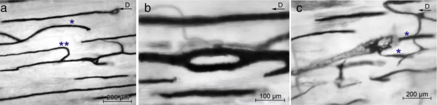
Other aspects of the network were the short-radius turn of the longitudinally oriented vessels (Fig. 6a) and the blind ends, character-ized by the sharp interruption of the injected vessel and documented by focusing on serial planes to avoid to misunderstand this unusual feature of the network with the otherwise common passage of the vessel in an
Fig. 4. Low-power view of the deepest cortical layer examined with multiplanar analysis (corresponding approximately to mid-cortex), showing the elongated meshes of the vascular network. The red vector in the top-right corner correspond to the diaphyseal axis. The long side of the network meshes shows a remarkable parallelism with the diaphyseal axis.
Fig. 5. Typology of nodes: (a) 3-arm node with bifurcation of the branches toward the distal extremity of the femur (type D), (b) bifurcation at right angle (type N) with the smaller caliber of the perpendicular branch, (c) 4-arm nodes (not classified for D or P nodes). [The vector in the right top corner indicates the diaphyseal axis toward the distal epiphysis. Bar = 100μm.]
Table 1
Mean number/field of 2-D crossing of vessels, mean number/field and density of true 3-D network nodes and distribution of nodes according to the number of arms.
3-D nodes/field 23.53 ± 3.19 (54.5%) 3-D nodes density (n/mm²) 6.59 ± 0.89 2-D intersections/field 42.23 ± 4.09
3-D nodes class 3 Arms 4 Arms 5 Arms Mean number/field±SD 22.07 ± 2.7 1.17 ± 0.73 0
upper or lower focal plane. Another so far unreportedfigure of the vessel network was the buttonhole with a vessel bifurcation soon followed by merging again of the two branches (Fig. 6b).
Cutting cones (Fig. 6c) appeared as a loop formed by twingled, injected vessels: the head was rounded shaped, while the tail thinner and extended (Fig. 7). Their density was 1.43 ± 0.463/mm2and the
mean length 400.7 ± 117.5μm. Discussion
The study of the injected vascular tree of the cortical bone with the multiplanar analysis had some limitations. (1) The analysis was restricted to a layer of the cortex equal to the depth offield of the microscope objective; the number of planes examined could be increased using glass or plexiglass slides of different thickness; however, it was not possible to get a continuous sequence of planes suitable for a digital 3-D reconstruction of the cortical vessel network. However in the volume of bone examined the method allowed to recognize true nodes, which in standard 2-D injection studies were always over-estimated because also the superimpositions of vessels on different planes were counted as nodes.
(2) Assessment of vessel internodal length presented the bias that only the segment of the vessel lying within a layer of bone equal to the depth offield of the examining objective can be measured: assuming as reference points two consecutive nodes or the margin of the microscopicalfield, a certain number of vessels present in the volume of bone examined are missed (those getting out from the focal plane
inside the microscopicalfield); moreover the lengths measured were shorter of the real internodal tract (those measured between a node and the margin of thefield), but also the other were subjected to a projectional error due to the thick section (Pazzaglia et al, 2007). Therefore these measurements are only indicative of the lower limit of internodal length.
The intracortical vascular architecture of long bones has been traditionally described as a regular system of longitudinal vessels with transverse connections (Thompson, 2002). This image of a regular geometry was derived by the classic 2-D studies with injection of the vascular tree or of the system of canals (Albu et al, 1973; Brookes and Revell, 1998; Hert and Hladíková, 1961; Lopez-Curto et al, 1980; Morgan, 1959; Nelson et al, 1960; Trias and Fery, 1979:Vasciaveo and Bartoli, 1961). Several attempts have been done to characterize the intracortical system of canals and vessels and figures have been given for the length of osteons and other parameters like diameter, shape and direction (Filogamo, 1946; Cohen and Harris, 1958; Vasciaveo and Bartoli, 1961; Albu et al, 1973). The static vascular anatomy depicted in the traditional model leads to surprisingly dogmatic views describing e.g. the periosteal and medullary sourced systems separately; however, the notion that the haemodynamics in systems external to the long bone could change the intracortical flow have been already considered by
Fernandez de Valderrama and Trueta (1965), Trueta and Cavadias, 1964 and Trias and Fery (1979). The multiplanar analysis applied in the present study suggested rather a network model. The morpho-metric parameters more appropriate to represent this system appeared to be those relative to the nodes and the analysis of their morphology and distribution could be interpreted in terms of development and mode of organization of the system. In this context the neo-angiogenesis cannot be considered separately from the bone modeling and remodeling, because the proliferation and the advancement of the vessels demand that a tunnel would be dug in advance in the compact cortex. The osteoclasts present on the front of advancement of the cutting head dig the tunnel, while the vascular loop stays in the back and at short distance from the resorbing cells, suggesting a link which is not only topographic, but also an interdependent relationship between the two functions “bone-resorption” and “neo-angiogenesis.”
We have documented that the network nodes can be formed with different mechanisms, like the bifurcation of an advancing cutting cone or the interception of the same with a pre-existing canal (either a periosteal-derived or an haversian); because the periosteal-derived are not longitudinally oriented, they form with the haversian vessels the right angle nodes (R). Considering two well established cortical bone anatomy, namely that the haversian canals have a prevalent straight trajectory and that the advancement direction of the cutting cones can be either proximally or distally oriented, as the growth vector of the proximal and distal growth plate cartilages (Pazzaglia et al., 2011), itfits with the higher number of acute than right angle nodes and with the balanced distribution of distal and proximal acute-angle nodes. Since the latter were the 93.63% of all, it is evident that the largest part of the mid-diaphysis is molded by the secondary remodeling. The remaining 6.37% of 4- and 5-arm nodes represented the remnants periosteal vessel network with its reticular design incorporated during the peripheral enlargement of the diaphysis as it was documented in bones of younger developing rabbits (Pazzaglia et al, 2007).
If bifurcation (mode 1) would be the only mechanism of node formation, two independent systems of convergent nodes should be present in the cortex, one formed only by proximal nodes and the other by distal nodes as shown in the scheme (Fig. 8). The observation of sequences alternating proximal and distal nodes is an evidence that interception of the cutting head with a pre-existent canals (mode 2) is operating in the network development. The frequency of not-convergent sequences is significantly higher of
Table 2
Mean number/field and percentage of P, D and N nodes. Mean number/field and percentage of convergent sequences of consecutive nodes (PP/DDPPP/DDD) and not-convergent (PD/DP/PDP/DPD/PPD/DPP/PDD/DDP).
3-Arm nodes/field 22.07±2.7
Nodes type P D N
Mean number/field±SD 9.27 ± 1.85 10.77 ± 0.74 2.33 ± 0.59⁎
Percentage 42% 48% 10%
Sequences of P and D nodes/field 4.9±0.64
Sequence type PP/PPP/DD/DDD PD/DP/PDP/DPD/PPD/DPP/PDD/DDP Mean number/ field±SD 1.27 ± 0.59 3.47 ± 0.98⁎⁎ Percentage 27% 73% ⁎ pb0.001. ⁎⁎ pb0.0001. Table 3
Frequency distribution of the vessel internodal length for classes of 400μm. n/field/ rabbit.
the convergent ones; interception resulted to be the main mechanism of the network formation. The examination of the sequences from proximal to distal or in the opposite direction does not change these results.
The 3-arm nodes of sub-class N in rabbits of this age were fewer and they also pertain to the interception of a cutting cone but with a periosteal-derived vessel.
Whether a node is formed by bifurcation or interception the role of osteoclasts is fundamental, because an unavoidable rule of cortical bone vascularization is that beforehand must be dug the tunnel and then the vessel can advance. It is therefore useful to focus the attention on the particular relationship between these cells and the vascular loop within the cutting cone: the loop is formed by an arteriole and one or more return capillary-like vessels, characterized by a thin wall of endothelial cells and a basal membrane (Shenk and Willenegger, 1964). For this particular pattern the cutting cone is the only sector of the intracortical network where the bloodflow can be clearly indicated with an arterialflow in the direction of advancement of the cutting cone and a returnflow in the opposite direction. The loop top stays back to the osteoclasts front and this is suggestive of a specific structural organization associated with digging out tunnels in the compact bone (Pazzaglia et al., 2010a,b), because in all the other sites bone remodeling is carried out by the same resorbing cells forming polycyclic pits with a limited depth. These aspects of the forming haversian canals suggest that the particular position of the
loop inside the cutting cone is in some way pushing the osteoclasts from the back to deepen into the bone matrix.
This study confirmed the longitudinal polarization of the network along the major axis of the bone; however, the vascular design appeared more irregular than that classically depicted, with other figures than the nodes alone, like the buttonhole figures, the short-radius bent of longitudinal vessels and the sharp-truncated vessels.
Thefirst can be explained by the mechanism of bifurcation of an advancing cutting cone, but remains unexplained why a diverging canal after a short tract returns to the original pathway.
The short-radius bends of longitudinal vessels imply that there has been a quick reversal of the advancement direction of the cutting cone during the process of the canal excavation and this should also suggest a role of the lying-behind vascular loop.
The sharp interruptions of the injected vessels could represent either a defect of the injection technique or correspond to the occlusion of a canal (sealed osteon) which has been documented with a relative frequency in the mid-diaphysis of long bones and represented an evidence of the plasticity of the intracortical vessel network to adapt to the variable haemodynamic conditions of the system (Congiu and Pazzaglia, 2010).
A full understanding of the general organization of the intracor-tical vessel network and of its development in the course of bone growth cannot leave out of consideration the relationship between the advancement direction of the canals when they arefirstly dug
Fig. 6. Peculiar aspects of the mid-diaphysis vessel network showing (a) vessels with a prevailing straight direction parallel to the longitudinal axis of the diaphysis; however, also bent vessels are seldom observed (*): the one illustrated presents a blind end with no passage in a upper or lower plane; the other vessel (**) after a straight trajectory changes sudden direction with a short-radius bend. (b) A buttonholefigure formed by an acute-angle bifurcation soon followed by a convergence of the two branches. (c) A cutting cone with the interlacing loops inside the canal: the vessels labeled by * lie on different planes. [The vector in the right top corner indicates the diaphyseal axis toward the distal metaphysis. Bars = 200μm (a and b); 100 μm (c).]
Fig. 7. Detail of a cutting cone with the branches of the vascular loop entering from the distal side; the advancement is proximally directed (arrows correspond to the cutting head). [The vector in the right top corner indicates the diaphyseal axis toward the distal metaphysis. Bar = 100μm.]
and the blood flow of the system in operating conditions. The morphology of the vascular loop inside the cutting cone has been earlier described and it gives a direct evidence of the bloodflow direction behind the osteoclasts of the advancing cutting head, but no statement is possible on the bloodflow direction in all the other branches of the network, which are formed by thin capillary-like vessels, while no larger vessels with a tunica muscularis have ever been observed inside the canals.
The study of the dynamics of the bloodflow in bones has been limited by the impossibility to use direct methods such as electromagnetic flow-meters or Doppler ultrasound and most of measurements have been performed with radionuclides (Tothill, 1984). It has been shown that alterations of the arterioles pressure and of the venous pressure outside the bone causes changes in the same direction in the bone marrow pressure (Michelsen, 1967; Lunde and Michelsen, 1970) and that bone vessels respond actively to several humoral and neurogenic stimuli (Stein et al, 1958; Gross et al., 1979; Brinker et al, 1990). However this regulatory capacity must be necessarily restricted to vessels with a tunica muscularis, while the whole intracortical network (with the only exception of the cutting cone loop) is formed by capillary-like vessels. It is therefore reasonable to suggest that in the meshes of the network, once the central canal has reached hisfinal sectional area, the flow direction can change in relation to the gradient of pressure between the afferents of the system (branches of the inner marrow, of metaphyseal and periosteal systems) and the drainage by the corresponding veins. Studies of blood flow in long bones with microspheres have shown thatflow rate heterogeneity is substantial
in the diaphysis (Willans and McCarthy, 1991). The morphology depicted in this study supports the notion of a multidirectional microvascular network allowing changes of flow according to functional requirements.
Acknowledgments
This study was supported by research funds of Brescia University (Dipartimento di Specialità Chirurgiche, Scienze Radiologiche e Medico-forensi) and by Centro Grandi Strumenti dell'Università dell'Insubria for the confocal microscope.
The authors are grateful to Mrs. Luisa Guidale for the assistance with the confocal microscope.
References
Albu, I., et al., 1973. Le sistème des canaux de la couche compacte diaphysaire des os long chez l'homme. Acta Anat. 84, 43–51.
Bridgeman, G., Brookes, M., 1966. Blood supply to the human femoral diaphysis in youth and senescence. J. Anat. 188, 611–621.
Brinker, N.R., et al., 1990. Pharmacological regulation of the circulation of bone. J. Bone Joint Surg. 72A, 964–975.
Brookes, M., Revell, W.J., 1998. Blood supply of bone. Scientific aspects. Springer Verlag, London.
Cohen, J., Harris, W.H., 1958. The three-dimensional anatomy of Haversian systems. J. Bone Joint Surg. Am. 40A, 419–434.
Congiu, T., Pazzaglia, U.E., 2010. The sealed osteons of cortical diaphyseal bone. Early observations revisited with scanning electron microscopy. Anatomical Records10.1002/ar21309
.
Cooper, D.M.L., et al., 2003. Quantitative 3D analysis of the canal network in cortical bone by micro-computed tomography. Anat. Rec. 274B, 169–179.
Fig. 8. Summarizing scheme of the network pattern in relation to its organization and development. Assuming the prevailing longitudinal polarization of the vascular loops of the advancing cutting cones and that they are directed either proximally or distally, the pattern of the network results from the mechanism of node formation. In scheme (A) it is hypothesized only nodes formed by bifurcation of the advancing vessel and as a consequence all the sequences would be P…n or D…n. In scheme (B) it is shown the effect of interception of a cutting cone with a pre-existing haversian canal with opposite polarization; sequences alternating D and P nodes are formed in this way.
Cooper, D.M.L., et al., 2006. Three-dimensional microcomputed tomography imaging of basic bone. Anat. Rec. 288A, 806–816.
Fernandez de Valderrama, J., Trueta, J., 1965. The effects of muscle action on the intraosseous circulation. J. Pathol. Bacteriol. 89, 179–186.
Filogamo, G., 1946. La forme et la taille des osteons chez quelques mammiferes. Arch. Biol. 57, 137–143.
Gross, M.P., Heistad, D.D., Marcus, N.L., 1979. Neurohumoral regulation of bloodflow to bones and marrow. Am. J. Physiol. 237H, 440–448.
Hert, J., Hladíková, J., 1961. Die Gefässversorgung des Haversschen Knoches. Acta Anat. 45, 344–361.
Kelly, P.J., 1968. Anatomy, physiology and pathology of the blood supply of bones. J. Bone Joint Surg. 56A, 766–783.
Kelly, P.J., James, J.P., 1968. Microangiographic and histological studies of vascular anatomy of the femur and tibia distal to femoral and iliac artero-venousfistulas in dogs. Anat. Rec. 162, 255–268.
Lopez-Curto, J.A., Bassingthwaighte, J.B., Kelly, P.J., 1980. Anatomy of the microvascu-lature of the tibial diaphysis of the adult dog. J. Bone Joint Surg. 62A, 1362–1369. Lunde, P.K.M., Michelsen, K., 1970. Determination of cortical bloodflow in rabbit femur
by radioactive microspheres. Acta Physiol. Scand. 80, 39–44.
Michelsen, K., 1967. Pressure relationships in the bone marrow vascular bed. Acta Physiol. Scand. 71, 16–29.
Mohsin, S., Taylor, D., Lee, T.C., 2002. Three dimensional reconstruction of Haversian systems in ovine compact bone. Eur. J. Morphol. 40, 309–315.
Morgan, J.D., 1959. Blood supply of growing rabbit's tibia. J. Bone Joint Surg. 41B, 185–203.
Nelson Jr., G.E., et al., 1960. Blood supply of the human tibia. J. Bone Joint Surg. 42A, 625–636. Pazzaglia, U.E., et al., 2010a. Scanning electron microscopy study of bone intracortical vessels using an injection and fractured surfaces technique. Anat. Sci. Int. 85, 31–37. Pazzaglia, U.E., et al., 2011. A review of the actual knowledge of the processes governing
growth and development of long bones. Fet. Pediat. Pathol. 30, 199–208.
Pazzaglia, U.E., et al., 2008. A model of the intracortical vascular system of long bones and of its development. Experimental study in rabbit femur and tibia. J. Anat. 213, 183–193.
Pazzaglia, U.E., et al., 2007. Design morphometry and development of the secondary osteonal system in the femural shaft of the rabbit. J. Anat. 211, 303–312. Pazzaglia, U.E., et al., 2010b. Morphometric analysis of the canal system of cortical bone.
An experimental study in the rabbit femur carried out with standard histology and micro-CT. Anat. Histol. Embriol. 39, 17–26.
Rhinelander, F.W., Stewart, C.L., Wilson, J.W., 1979. Bone vascular supply. Skelet. Res, New York, San Francisco, London.
Rogers, W.H., Gladstone, H., 1950. Vascular foramina and arterial supply of the distal end of the femur. J. Bone Joint Surg. 32A, 867–874.
Shenk, R., Willenegger, H., 1964. Zur Histologie der primären Knochenheilung. Langenbecks Arch. Chir. 308, 440–452.
Stein, A.H., Morgan, H.C., Porras, R.F., 1958. The effect of pressor and depressor drugs on intramedullary bone-marrow pressure. J. Bone Joint Surg. 40A, 1103–1110. Stout, S.D., et al., 1999. Computer-assisted 3D reconstruction of serial sections of
cortical bone to determine the 3D structure of osteons. Calcif. Tissue Int. 65, 280–284.
Thompson, J.C., 2002. Netter's concise atlas of orthopaedic anatomy. MultiMedia USA Inc., Teterboro, N.J. USA.
Tothill, P., 1984. Bone bloodflow measurement. J. Biomed. Eng. 6, 251–256. Trias, A., Fery, A., 1979. Cortical circulation of long bones. J. Bone Joint Surg. 61A,
1052–1059.
Trueta, J., Cavadias, A.X., 1964. A study of the blood supply of the long bones. Surg. Gynecol. Obstet. 118, 485–498.
Vasciaveo, F., Bartoli, E., 1961. Vascular channels and resorption cavities in the long bone cortex of the bovine bone. Acta Anat. 47, 1–33.
Willans, S.M., McCarthy, I.D., 1991. Heterogeneity of bloodflow in tibial cortical bone: an experimental investigation using microspheres. J. Orthop. Res. 9, 168–173.