ScienceDirect
Available online at www.sciencedirect.com
Procedia Manufacturing 47 (2020) 472–478
2351-9789 © 2020 The Authors. Published by Elsevier Ltd.
This is an open access article under the CC BY-NC-ND license (https://creativecommons.org/licenses/by-nc-nd/4.0/) Peer-review under responsibility of the scientific committee of the 23rd International Conference on Material Forming. 10.1016/j.promfg.2020.04.340
10.1016/j.promfg.2020.04.340 2351-9789
© 2020 The Authors. Published by Elsevier Ltd.
This is an open access article under the CC BY-NC-ND license (https://creativecommons.org/licenses/by-nc-nd/4.0/) Peer-review under responsibility of the scientific committee of the 23rd International Conference on Material Forming.
ScienceDirect
Procedia Manufacturing 00 (2019) 000–000
www.elsevier.com/locate/procedia
2351-9789 © 2020 The Authors. Published by Elsevier Ltd.
This is an open access article under the CC BY-NC-ND license https://creativecommons.org/licenses/by-nc-nd/4.0/) Peer-review under responsibility of the scientific committee of the 23rd International Conference on Material Forming.
23rd International Conference on Material Forming (ESAFORM 2020)
Process Parameters Optimization in Micromilling of Watch Mechanism
Features
Andrea Abeni
a,*, Alessandro Metelli
a, Gabriele Allegri
a, Aldo Attanasio
aa Department of Mechanical and Industrial Engineering, University of Brescia, V. Branze 38, Brescia, 25123, Italy
* Corresponding author: [email protected]
Abstract
The micro machining technology is a widespread process in several industrial sectors, such as the electronics, the moulds fabrication, the biomedical field and the horology. The main advantages of micro-milling are the low material scrap, the high accuracy and repeatability, the possibility to manufacture small size features and the respect of the geometrical and dimensional tolerances. For these reasons, micro-milling is suitable to manufacture precision components in watchmaking industry. In the high-end horology field, high geometrical precision and elevated surfaces quality are key requirements. An optimal process parameters set should be identified to comply the very strict quality standards. This paper reports the results of an optimization performed to define how to make high-quality main-plates and bridges of wristwatch movement. The dimensions, the geometry and the surface finishing of holes, pins and pockets are the optimized wristwatch features. During the optimization, cutting speed, feed rate and depth of cut were varied and measurements of geometrical errors and roughness were performed to understand how the process parameters affect the final product quality. The experimental tests were conducted on “Nickel Silver” (CuNi18Zn20) samples by using an ultraprecision 5-axis milling center located in controlled environment. The surface roughness, the burrs extension and the geometrical errors were measured by using a multifocal 3D microscope, a coordinate measuring machines and an autofocus 3D laser probe. This study allowed to manufacture a wristwatch movement in conformity with the required technical characteristics.
© 2020 The Authors. Published by Elsevier Ltd.
This is an open access article under the CC BY-NC-ND license https://creativecommons.org/licenses/by-nc-nd/4.0/) Peer-review under responsibility of the scientific committee of the 23rd International Conference on Material Forming. Keywords: Micromilling; Process optimization; Watch mechanism
1. Introduction
Micro machining includes a high number of processes characterized by a relative movement between the workpiece and a tool with a diameter lower than 1 mm. The material removing is determined by the contact between the tool cutting edge and the workpiece along a defined path, in order to obtain the final shape of the product. In 3-axis micro milling, the feed and the rotational movements are typically owned by the tool while the workpiece is bounded to an appropriate clamping system positioned in the workspace. Several geometrical features can be manufactured through the micro milling and the products quality is strictly dependent on the process parameters [1]. The optimization of the cutting speed, the feed rate and the
depth of cut results in the best compromise between the machining quality and the production time.
The micro milling may guarantee high precision, flexibility, excellent surface finishing, tight geometrical and dimensional tolerances with a low material scrap in the micrometric magnitude scale. The process parameters strongly influence the surface roughness, the holes and pins geometrical accuracy (dimension and circularity), the burrs extension and distribution. The component assembly and the final product functioning are strictly correlated to the machining quality, which assumes a key role in the industrial context. The micro milling advantages allow its widespread in several manufacturing fields, such as electronics, automotive, aerospace, moulds fabrication, biomedical and horology [2].
Andrea Abeni et al. / Procedia Manufacturing 47 (2020) 472–478 473 2 Author name / Procedia Manufacturing 00 (2019) 000–000
In the watchmaking industry, the micro milling represents the most important process and it is used to fabricate the majority of watch movement components [3,4]. A mechanical watch caliber is composed by a number of components ranging between some dozens to several hundreds in relation to its functional complications. The diameter of a wristwatch movement typically oscillates between 17 mm and 36 mm and the thickness is approximately equal to 4 mm. The high number of jointed components in a very low volume implicates the employment of small size parts. The slightest components possess features with a dimension of some hundreds micrometers and consequently their manufacturing is a difficult challenge. The keeping time is the main characteristic of a mechanical watch and it can be guaranteed by means of a high precision in components geometry and coupling.
The watch movements components can be divided in main plates, bridges, wheels, shafts, screws, springs, jewels and levers but micro milling is not used to produce all the parts. More specifically, micro milling is commonly utilized to fabricate the main plates and the bridges. These components constitute the caliber structure and they are typically characterized by micro-holes, pins and pockets. The listed features are essential to hold the parts that composed the driveline in the correct position. Tight tolerance, high quality surface and lack of burrs are crucial requirements to ensure the correct functioning of the watch movement. The holes have interference coupling with the jewels that are used to reduce the friction with the shafts of the wheels. Typical diameters of the holes are equal to some hundreds of micrometers and high precision is necessary to guarantee the correct gear engagement. The pins ensure the coupling between the main plates and the bridges and their dimension is comparable with the diameter of the holes. The diameter of the pins must be the same along the entire height to avoid an uncorrected interference with the holes into the bridges. The pockets are fabricated to accommodate the wheels and their depth is crucial for a corrected wheels positioning.
Micro mills with diameters ranging between 0.2 mm and 0.8 mm are commonly employed to manufacture the described features. Nickel silver, brass and gold are some of the materials used to produce main plate and bridges, but the CuNi18Zn20 is probably the most common alloy in the horology field. The micro machining of CuNi18Zn20 requires coated tools, low feed rate, high cutting speed and the depth of cut is limited to few tenths of a millimeter. A deeper analysis of the process parameters is essential to achieve high quality results [5]. A high number of researches dealt with the issues related to the machining miniaturization. The size effect, the tool run-out, higher than excepted cutting forces, inadequate surface finishing are some examples of the most analyzed topics [6,7]. The experimental approach is often supported with analytical model, FEM simulations and predictive models. [8,9] On the other hand, a lack of information affects the manufacturing of watch movement. In literature there are not papers which deals with the criticisms and the issues which afflicts the watch making industry. A scientific and methodical approach is required to improve the product final quality and to satisfy the strict requirements of the horology industry.
This paper shows a study case of a movement fabrication performed in the laboratories of the University of Brescia. The first main plates and bridges were fabricated by using the process parameters suggested by a catalogue. As visible in Fig. 1, the poor quality of the machined surface strongly affects the movement functionality.
Fig. 1. Features of the original main plate: (a) an irregular hole; (b) extended burrs; (c) conicity of the pin.
The circularity of the holes is higher than the allowed geometrical tolerance (Fig. 1a). The burrs are widely diffused, and their size compromises the mechanical coupling between parts (Fig. 1b). Moreover, the pins are characterized by bulging effect and they show an excessive conicity (Fig. 1c). The optimization was performed in order to solve the critical issues and finally to manufacture an adequate main plate.
A prototype was designed to include the key features in a limited volume. The process parameters were varied on three levels and the workpiece machining was repeated by changing their combination. A coordinate measuring machines was used to measure the diameter and circularity of the holes while an autofocus 3D laser probe was employed to measure the roughness Sa of the pockets surface [10]. Finally, the conicity of the pins, the burrs extension and the surface quality were checked by using a multifocal 3D microscope. The optimal parameters set was selected by considering also the time production necessary to fabricate each prototype.
2. Materials e methods
The machining tests were performed on CuNi18Zn20, a copper-nickel alloy widely utilized in watchmaking industry due to its proprieties. High mechanical resistance, good elasticity, elevated corrosion resistance, brightness and good machinability are the most relevant material properties.
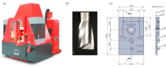
Fig. 2. (a) KERN Pyramid Nano; (b) micro mill SECO 905L008-MEGA-T; (c) 2D view of the sample geometry.
474 Andrea Abeni et al. / Procedia Manufacturing 47 (2020) 472–478
ScienceDirect
Procedia Manufacturing 00 (2019) 000–000
www.elsevier.com/locate/procedia
2351-9789 © 2020 The Authors. Published by Elsevier Ltd.
This is an open access article under the CC BY-NC-ND license https://creativecommons.org/licenses/by-nc-nd/4.0/) Peer-review under responsibility of the scientific committee of the 23rd International Conference on Material Forming.
Table 1 summarizes the chemical composition of CuNi18Zn20 alloy.
Table 1. Chemical composition of CuNi18Zn20.
Cu Ni Zn Mn
Wt [%] 62.0 18.0 19.0 rem. The Fig. 2 shows the milling center (Fig. 2a) and the micro
mill (Fig. 2b) utilized for the experimental campaign [11,12]. A nano-precision 5-axis milling center Kern Pyramid Nano with a positioning scatter of 0.3 microns was utilized to manufacture the samples. The CNC machine mounts a spindle able to develop a torque of 1.5 Nm with a maximum rotational speed of 50,000 rpm. These characteristics make this milling center suitable for the horology industry. The machining was executed by using a SECO mill with a nominal diameter equal to 0.8 mm. The tool features were measured by using a 3D multifocal microscope Hirox RH-2000 which guarantees an accuracy of 0.8 μm. Table 2 shows the micro mill most meaningful proprieties and the measurements results. As shown in Fig. 1, the watch movement fabricated with the suggested process parameter did not satisfied the quality requirements. An experimental campaign was designed to increase the machining quality and to maintain an acceptable time production. The milling tests were executed to individuate the best process parameters set. An experimental approach requires to fabricate a high number of main plates and bridges with different combinations of cutting speed, feed rate and depth of cut. This approach is time consuming and the mill should be frequently substituted to avoid that tool wear affects the experimental results.
Table 2. Measured micro end mill features (Hirox RH-2000).
Propriety Value
Manufacturer Code
Nominal diameter [μm] Measured diameter (with standard deviation) [μm]]
Measured cutting-edge radius (with standard deviation) [μm] SECO 905L008-MEGA-T 800 795 ±1 6 ±0.8 Helix angle [°] 20 Rake angle [°] 4
Material Tungsten Carbide
Material coating Titanium Nitride
The prototype geometry is shown in Fig. 2c. The samples have an overall dimension of 9 mm x 6 mm x 0.9 mm. A rough machining was performed to cut a block with the correct dimensions form a sheet portion with a thickness of 1.2 mm. A pocket with a constant depth equal to 0.5 mm was machined by leaving three pins. The pins (Φ 0.6 mm, Φ 1 mm and Φ 2 mm) are typically employed in watchmaking industry. A through-hole with a diameter of 1 mm was machined by using the micro mill. The tool drilled the workpiece surface with a normal attack and subsequently it was moved along a circular path.
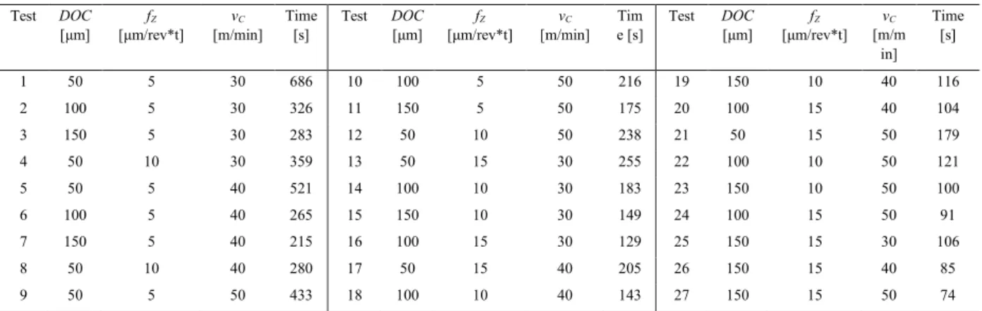
Each process parameter was changed on three levels for a total number of 27 combinations. Table 3 lists the values of the depth of cut, the feed per tooth and the cutting speed used to machine the samples.
Table 3. Process parameters.
Process parameter Original Value A Value B Value C Depth of cut DOC [μm] 250 50 100 150 Feed per tooth fZ
[μm/rev*tooth] 15 5 10 15
Cutting speed vC [m/min] 60 30 40 50
The cutting speed used to machine the main plate shown in Fig. 1 was equal to 60 m/min but the burrs demonstrated that a lower speed is necessary. For this reason, three smaller cutting speeds were selected. A minimum value of 30 m/min is required to cut the material with an adequate productivity. The feed per tooth ranges between a minimum of 5 and a maximum of 15 μm/rev*tooth, which was the feed per tooth adopted for the main plate fabrication. Lower values are necessary to improve the surface finishing [13,14]. The depth of cut has a strong influence on the workpiece roughness and on the pin shape. The main plate shown in Fig. 1 was manufactured with
a depth of cut of 250 μm, therefore the samples were machined with three depth of cut equal to 50 μm, 100 μm, 150 μm.
The machining tests were executed in a controlled environment with a temperature of 20 ±0.5°C and humidity of 35 %. The samples surface was lubricated by a constant direct flow of emulsified oil. Tool wear was constantly monitored, and it resulted neglectable. A commercial CAM was utilized to write the CN programs. The software indicated also the machining times, which are collected in Table 4.
Andrea Abeni et al. / Procedia Manufacturing 47 (2020) 472–478 475 4 Author name / Procedia Manufacturing 00 (2019) 000–000
Table 4. List of the process parameters and production time.
The production times oscillate in a wide range between a minimum of 74 s and a maximum of 686 s with an average time of 224 s. The combinations between low feed rate and low depth of cut determines unacceptable productivity. Furthermore, the 80% of the tests have a production time between 74 s and 283 s, which can be considered a reasonable productivity range. For this reason, the process parameters sets 1, 2, 4, 5 are not efficient, but the tests were performed in order to have a benchmark for the quality of the other machined samples. Once the machining tests were performed, then samples quality was checked by using a multifocal 3D microscope, a coordinate measuring machines and an autofocus 3D laser probe. The multifocal microscope Hirox RH-2000 was employed to carry out a visual inspection of the samples. In particular, the burrs occurrence and the features shape were evaluated. Moreover, each pin conicity was measured three times at different magnifications. The CMM machine Mitutoyo Quick Scope was utilized to measure the holes and pins diameter and circularity with an accuracy of 2.5 μm. Each measure was repeated three times with three different magnification. Finally, the roughness Sa was measured by using the autofocus 3D laser probe Mitaka PF-60. The instrument can be utilized to measure several roughness parameters. The Sa is the extension of Ra to a surface [15]. It is calculated by using the Eq. 1 as the difference in height of each point compared to
the arithmetical mean of the surface:
𝑆𝑆𝑎𝑎= 𝐴𝐴1∬|𝑧𝑧(𝑥𝑥, 𝑦𝑦)| 𝑑𝑑𝑥𝑥𝑑𝑑𝑦𝑦 (1)
The Sa measurement is time consuming, but it offers a more detailed information about the entire surface finishing. In horology, high precision along the surfaces in required to guarantee accurate contact between the components faces. This specific requirement makes the measure of the Sa an interesting quality procedure in watchmaking industry. The roughness was evaluated by considering a sample surface equal to 1 mm x 1 mm on the base of the pocket.
3. Results
The surface check of the machined sample was performed by using the microscope Hirox RH-2000 with a magnification X250.
Fig. 3 shows three significant examples (Test 1, 9 and 27).
Fig. 3. The machined surface of (a) sample 1; (b) sample 9; (c) sample 27. The first sample exhibits an excellent surface quality, the burrs are absent, and the circularity of pins and holes is optimal. The diameters of pins and hole have a deviation from the nominal value lower than 2 micrometers. Test 1 was executed with the minimum values of feed per tooth, depth of cut and cutting speed. Sample number nine was machined with the same feed per tooth and depth of cut, but the cutting speed was increased from 30 m/min to 50 m/min. The consequence was an increment of the burrs, but their dimension is limited, and the defect can not compromise the mechanical coupling between parts.
The sample 27 was fabricated with the maximum values of the feed per tooth, the depth of cut and the cutting speed. The burrs are widely diffused, and their dimension is not neglectable. An analogue burrs distribution was observed on samples 25 and 26. Each of these tests was performed with a feed per tooth of 15 micrometers and a depth of cut of 150 micrometers, therefore the combination between the maximum feed rate and depth of cut can not be considered acceptable. The pins and the hole of the sample 27 exhibits also unacceptable dimensions and shape. In particular, the pin with a diameter of 0.6 mm was machined with an irregular shape. The same defect was detected in the samples machined with a feed per tooth of 10 micrometers associated to a cutting speed of 40 m/min and 50 m/min and in the samples fabricated with a feed per tooth of 15 micrometers regardless of the cutting speed.
Test DOC
[μm] [μm/rev*t] fZ [m/min] vC Time [s] Test DOC [μm] [μm/rev*t] fZ [m/min] vC Time [s] Test DOC [μm] [μm/rev*t] fZ [m/mvC in] Time [s] 1 50 5 30 686 10 100 5 50 216 19 150 10 40 116 2 100 5 30 326 11 150 5 50 175 20 100 15 40 104 3 150 5 30 283 12 50 10 50 238 21 50 15 50 179 4 50 10 30 359 13 50 15 30 255 22 100 10 50 121 5 50 5 40 521 14 100 10 30 183 23 150 10 50 100 6 100 5 40 265 15 150 10 30 149 24 100 15 50 91 7 150 5 40 215 16 100 15 30 129 25 150 15 30 106 8 50 10 40 280 17 50 15 40 205 26 150 15 40 85 9 50 5 50 433 18 100 10 40 143 27 150 15 50 74
Fig. 4. (a) Pin conicity; (b) pins circularity.
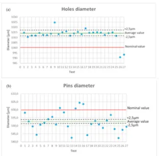
Fig. 5. (a) Holes diameter; (b) pins diameter.
The Hirox RH-2000 was employed also to measure the conicity of the pins with the diameter equal to 0.6 mm. The tilt of the lateral surface compared to the normal at the pocket surface oscillates between 0° and 0.5°, as visible in Fig. 4a. The inclination does not compromise the mechanical coupling under any circumstances.
Quantitatively measurements were performed after the qualitatively evaluation based on the observations with the microscope. The CMM machine Mitutoyo Quick Scope was employed to measure the diameters of the three pins and the hole. The pins with a nominal diameter of 1 mm and 2 mm exhibit high precision and low variability. The most significant criticalities were individuated about the fabrication of the hole and the smaller pin. Fig. 5a shows the average value of the hole
diameter measurements of each test. The upper and lower bounds were built by considering the accuracy of the CMM
machine. The points included in the band can be approximated with their average value, equal to 1.014 mm. The data highlights elevated precision and independence between holes diameter and the process parameters. Moreover, the offset between the average value and the nominal diameter implicates low accuracy. The offset is equal to 14 micrometers and the percentage error is 1.4 %.
Pins circularity is visible in Fig. 4b. It slightly increases as the process parameters increase, but it can be considered acceptable for all tests except Test 26 and 27. Fig. 5b shows an
average pin diameter of 0.593 mm with an offset to the nominal diameter equal to 7 micrometers. The percentage error is 1.2 % and it is comparable with the error on the hole diameter. The precision in pin manufacturing is lower than the precision in hole manufacturing. The data analysis does not highlight a relevant dependence between the diameter of the pins and the process parameters.
Fig. 6. Measurement of roughness Sa for (a) tests at vC = 30 m/min; (b) tests at vC = 40 m/min; (c) tests at vC = 50 m/min.
Andrea Abeni et al. / Procedia Manufacturing 47 (2020) 472–478 477 6 Author name / Procedia Manufacturing 00 (2019) 000–000
The roughness Sa must be considered to select the optimum process parameters set. A Mitaka PF-60 3D laser probe was employed to measure the roughness Sa for each sample. The Sa oscillates in a wide range between a minimum of 0.111 μm and a maximum of 0.696 μm. Fig. 6 summarizes the measurement
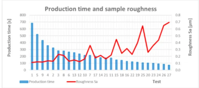
by dividing the test in three groups. Each group corresponds to a different cutting speed. The feed per tooth and the depth of cut have a meaningful influence on the samples roughness. In each case, the Sa increases as the feed rate increases and similarly the Sa increases as the depth of cut increases. The cutting speed does not significantly influence the pocket roughness. Fig. 7 shows the correlation between the roughness and the time production.
Fig. 7. Production time and roughness Sa
The best surface finishing was obtained by using the combination between minimum depth of cut, feed per tooth and cutting speed. Moreover, the roughness increases as the time production decreases. The best compromise can be individuated for tests 17, 14, 21. For these tests, the time production oscillates between 179 s and 205 s while the roughness ranges between 0.164 and 0.214 micrometers. Test 17 and 21 were performed with fZ = 15 μm. The pins with diameter equal to 0.6 mm are consequently irregular. For this reason, the best process parameters combination was individuated in Test 14, which shows an actual diameter of 600.8 ± 2.5 μm, a roughness Sa = 0.214 μm and a production time equal to 183 s.
The defect visible in Fig. 1c never occurred during the experimental campaign. On the other hand, the combination between fZ = 15 micrometers and DOC = 150 micrometers determines excessive burrs distribution. Moreover, a not neglectable scale effect occurs during the fabrication of the pins with a diameter of 0.6 mm. In fact, the final geometry results unregular for the tests characterized by fZ = 10 μm associated to vC = 10/15 m/min and fZ = 15 μm regardless the cutting speed. These results implicate that the manufacturing of geometrical features with dimension lower than 1 mm should be performed by using low feed rate coupled to low cutting speed.
A depth of cut DOC = 100 μm, a feed per tooth fZ = 10 μm/rev*tooth and a cutting speed of vC = 30 m/min were utilized to fabricate new main plate and bridges. The results are visible in Fig. 8 and Fig. 9. The process optimization allowed to achieve a remarkable quality improvement. The original main plate exhibited a lot of burrs, which were completely absent in the new main plate. The holes were irregular, and the jewels coupling was not allowed. The jewels assembly was practicable for the optimized main plate.
Fig. 8. Results comparison about (a) the pin conicity; (b) the radial hole shape.
Fig. 9. Comparison between the features machined with (left) the original parameters; (right) the optimized parameters.
The pins on the new movement are circular and bulging effects were not present. Moreover, the radial hole was characterized by an adequate circularity.
4. Conclusion
The experimental tests allow to understand how the process parameters influence the quality of some important features of a watch movement. The designed features were adequate to achieve a deeper understand about the process parameters influence on micro-products quality. The ultra-precision machining center and the high performing measuring instruments allowed to conduct high-quality experimental tests and to collect meaningful data.
In particular, the pin conicity is acceptable for all the process parameters combinations. On the other hand, the pins and holes machining highlighted a lack of accuracy due to an offset between the nominal and the actual diameters. The offset is almost constant and approximately equal to the 1.5 % of the nominal diameter. The error does not avoid a correct mechanical coupling, but it could be solved by reducing the tool run-out [16,17]. In fact, the pins effective diameters are lower than the nominal diameter; vice versa, the hole effective diameters are higher than the nominal dimeter. For this reason, the tool rotation eccentricity is probably the cause of the error and it could be solved by adopting a more performing tool holder.
The roughness measurements demonstrated that the roughness increases as the feed rate increases. This trend is commonly reported in literature. A more interesting result is the strong correlation between the depth of cut and the roughness. A possible cause is an increase of the chatter vibration as the depth of cut increases. In fact, a major chip cross section implicates higher cutting force and higher workpiece vibration. In conventional machining the effect is neglectable, but in micro scale it could have a considerable weight.
The paper described a scientific approach to optimize a micro-machining experimental case. A equivalent micro geometry was designed and manufactured to investigate the correlation between process parameters and geometrical
tolerances, dimensional tolerances and roughness. Further studies will be conducted with different micro tools on different geometries to optimize the quality of multiple micro-features. A deeper review of the tool run-out issue will be performed to improve the accuracy in the micro holes and micro pins fabrication.
Acknowledgments
The Authors wish to thank Simitecno Srl for the technical support during the research.
References
[1] Schorderet A, Herzog R, Jacquod N, Marchand Y, Prongué C. Productivity Increase of High Precision Micro-Milling by Trajectory Optimization. HSM 15th International Conference on High Speed Machining 2019.
[2] Gherman L, Gleadall A, Bakker O, Ratchev S. Manufacturing Technology: Micro-machining. Micro-Manufacturing Technologies and Their Applications 2017; 97-127.
[3] Su S, Du R. Signature analysis of mechanical watch movements. Mechanical Systems and Signal Processing 2007; 21:3189-3200.
[4] Bian R, Ferraris E, Ynag Y, Qian J. Experimental Investigation on Ductile Mode Micro-Milling of ZrO2 Ceramics with Diamond-Coated End Mills. Micromachines 2018; 9(3):127.
[5] Thepsonthi T, Özel T. Multi-objective process optimization for micro-end milling of Ti-6Al-4V titanium alloy. The International Journal of Advanced Manufacturing Technology 2012;63(9-12):903-914.
[6] Attanasio A, Garbellini A, Ceretti E, Giardini C. Force modelling in micromilling of channels. International Journal of Nanomanufacturing 2015; 11(5-6):275-296.
[7] Özel T, Karpat Y. Identification of constitutive material model parameters for high-strain rate metal cutting conditions using evolutionary computational algorithms. Materials and Manufacturing Processes 2007;22:659–667. [8] Dornfeld D, Min S, Takeuchi Y. Recent Advances in Mechanical Micromachining. CIRP Annals - Manufacturing Technology 2006;55(2):745-768.
[9] Karagiannis S, Stavropoulos P, Ziogas C, Kechagias J. Prediction of surface roughness magnitude in computer numerical controlled end milling processes using neural networks, by considering a set of influence parameters: an Aluminium alloy 5083 case study. Proc Inst Mech Eng B J Eng Manuf 2013; 228(2):233–244.
[10] D’Urso G, Giardini C, Quarto M. Characterization of surfaces obtained by micro-EDM milling on steel and ceramic components. International Journal of Advanced Manufacturing Technology 2018;97(5-8):2077-2085.
[11] Allegri G, Colpani A, Ginestra PS, Attanasio A. An Experimental Study on Micro-Milling of a Medical Grade Co-Cr-Mo Alloy Produced by Selective Laser Melting. Materials 2019;12:13.
[12] Abeni A, Lancini M, Attanasio A. Characterization of machine tools and measurement system for micromilling. Nanotechnology and Precision Engineering 2019;2:23–28.
[13] Lu X, Zhang H, Jia Z, Feng Y, Liang S. Floor surface roughness model considering tool vibration in the process of micro-milling. The International Journal of Advanced Manufacturing Technology 2018;94(9-12):4415-4425. [14] Beruvides G, Castaño F, Quiza R, Haber R. Surface roughness modeling and optimization of tungsten–copper alloys in micro-milling processes. Measurement 2016,86:246-252.
[15] ISO 25178-2:2012 Geometrical product specifications (GPS). Surface texture: Area. Part 2: Terms, definitions and surface texture parameters. [16] Attanasio A. Tool run-out measurement in micro milling. Micromachines 8:221-228
[17] Attanasio A, Abeni A, Özel T, Ceretti. Finite element simulation of high speed micro milling in the presence of tool run-out with experimental validations. The International Journal of Advanced Manufacturing Technology 2018;100(1-4):25-35.