Integrating MRP
in production systems simulation tools
Claudia Battista*,Giulia Dello Stritto*, Raffaele Iannone**, Massimiliano M. Schiraldi*
*Department of Enterprise Engineering, “Tor Vergata” University of Rome, Via del Politecnico 00133 Roma – Italy ([email protected]; [email protected], [email protected])
**Department of Industrial Engineering, University of Salerno, Via Ponte Don Melillo, 84084 Fisciano (SA) – Italy ([email protected])
Abstract: Literature review suggests concentrating on the development of new reference model for
manufacturing system simulation, which may implement an operation logic much closer to real industrial contexts. A production system modelling tool should be designed with the aim of standardizing and simplifying the simulation of manufacturing processes and to widespread this approach in SMEs. With this aim, the authors got committed in designing a reference model for providing a structural framework to support shop-floor simulation and optimization. This paper presents the basic framework logic and structure of the simulation tool, showing how it is possible to represent it in Business Process Modelling Notation (BPMN). On top of this, the efforts of implementing an MRP module on top of a simulation took which was originally conceived to embed look-back material handling policies area described, together with the operative solutions chosen to reach the integration.
Keywords: simulation, production systems, MRP, BPMN
1. Introduction
Simulation tools provide a virtual laboratory where a user can observe a phenomenon in a controlled way and manage all conditions that influence it. Several authors consider simulation an useful approach to study and optimize production processes, and they agree on simulation potentialities in analysing dynamic and stochastic behaviour of a manufacturing system, predicting its operational performance and pointing out its critical factors (Smith, 2003; Hlupic, 1999; Law, 1991). Since 80’s some researchers have been interested in developing tools for simulating a production and procurement schedule keeping into account resources capacities together with the desired production rate (Lindeque & Kruger, 1987). Literature recognizes the need of developing a methodology to integrate enterprise resource planning systems with the inherent ability to handle the uncertainties of discrete events simulators (Moon, 2005), with specific regard to Material Requirement Planning (MRP) applications. MRP procedure is widely used in support to production scheduling in many manufacturing companies but it is still implemented under deterministic hypotheses: its capability as an effective planning tool when there is a high degree of uncertainty is, indeed, questionable (Sun, 2009). Uncertainty is simply kept into account oversizing lead times and/or safety stocks: this approach implies several well-known inefficiencies and may be improved. For this reason, MRP integration in simulators may be useful to keep into account random variables in an analytical model, determining the effects of factors such as forecast errors
and processes variability, eventually allowing to dynamically compute the relative effects on key performance measures. Several authors provided the examples of some MRP application to complex production systems models (Harris, 2002; Mula, 2006; Harish, 1999) where mathematical constraints are used to consider finite capacity. Although there are even some MRP custom-made tools that can partially simulate production dynamic, these applications do not match flexibility and “ease of use” requirements of the tools demanded by the market. Indeed a lack of a commercial software that incorporates all the strategic functionalities for modelling several manufacturing phases in a user-friendly way is considered one of the main simulation’s drawbacks. In this paper we propose a standard framework to model all the different production and storage policies, natively embedded in a simulation tool called OPUS (Optimizing Production [processes] Using Simulation). Our goal is to integrate a simulation tool addressed to the Italian manufacturing SMEs with an MRP procedure in order to stick much closer to real production systems requirements. For this reason we developed the embedded modelling framework through an innovative approach based on an intensive usage of
Business Process Modelling Notation (Object
Management Group’s BPMN). This notation has helped to conceive a model that is strictly linked to business
processes, on top of simplifying the
2. The reference model architecture
The reference model architecture presents a hierarchical structure with three different layers:
a. Logic layer;
b. Communication layer; c. Operations layer.
The “Logic layer” contains information about the bill of material (BoM), the process chart (PC) for each finite product, the master production schedule (MPS), Part Number (P/N) codes, storage locations, etc. It gathers all essential information to build the simulation model: data input forms are analogous to the typical data structures of an industrial plant, thus not any abstraction effort to develop the real system model is required.
The “Communication layer” contains the framework working logic that define resources interactions and their relationships into the model. All the different production and inventory control policies on top of all the typical processes and work methods in a manufacturing plant are formalized using BPMN representation in order to standardize processes and simplifying their software implementation. Thus logic and communication layers allow communication – information flows – among resources belonging to the following “Operations layer”. Specifically each of them manages different lists that guarantee the coherence of the physical and information flows progress (table 1)
The “Operations layer” is dedicated to the reproduction of resources’ behaviour, production layout and material flows. Model hierarchy y x M1 M2 M3 W1 T1 B1 B2 BoM MPS PC Mng Policies Production Flow Logic layer Communication layer Operations layer Information Flow Production hierarchy y x ERP Mng Policies Shop floor Planning Scheduling
Figure 1. Reference model hierarchy
The model is characterized by four different kind of resources: machines (Mi), stock buffers (Bj), transporters (Tk) and workers (Wr). Each resource is defined by user according its layout position and some technical features. In the following table there is an example of parameters used to describe a machine Mi.
Resource Communication list
Machine
Production order list Material orders list WIP list Buffer Picking list
Inventory on hand list
Storage request list Material release list
Tab. 1: Resources communication lists
Thus this hierarchical structure allows to separate the model operating logic (which gets data from the management information system) from the physical context (which is built with shop-floor data): the information needed to reproduce any management policy is collected in the logic and communication layers, while the information dealing with resources is in the operation layer.
3. The usage of BPM notation
The reference model, on which OPUS kernel is based, has been formalized in BPM notation in order to propose a standard of representation and functioning of manufacturing production processes that could be useful to support the design of simulation software in general. All basic archetypes of industrial production systems are embedded in the framework and described with BPMN diagrams. This approach allows representing all the company’s business processes – up to a high detail level – and it has been chosen to formalize all the functions implemented in the OPUS simulator. BPMN representation helps to standardize processes, simplifying their modelling and the implementation/coding of software. Moreover, it has the advantage to be directly translatable in XML format. As a result, the BPMN reference model has effectively supported the software house which is developing the second release of the OPUS simulator; the software has been easily and directly translated into the Java classes and methods of the related objects, in order to obtain a complete compliance among the tool simulation logic and real industrial environment logic.
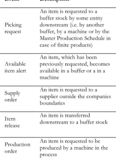
OPUS execution is based on discrete event simulation: an event occurrence triggers several functions that set information and physical flow between resources. Thus, the reference framework is based on events as well, and ten triggers have been chosen to represent the main events in the typical manufacturing production process:
Event Description
Picking request
An item is requested to a buffer stock by some entity downstream (i.e. by another buffer, by a machine or by the Master Production Schedule in case of finite products) Available
item alert
An item, which has been previously requested, becomes available in a buffer or a in a machine
Supply order
An item is requested to a supplier outside the companies boundaries
Item release
An item is transferred downstream to a buffer stock Production
order
An item is requested to be produced by a machine in the process
Setup end A setup is completed and the machine is ready to process another kind of item Failure
occurrence
A failure occurs in a machine and the machining phase is stopped
Reparation
end A machine is restored after the occurrence of a failure Production
end w/scrap
A machining phase is completed but the result is not compliant to quality requirements Production
end
A machining phase is completed and the result is compliant to quality requirements
OPUS discrete event simulation manages all events thanks to the Future Event List (FEL), a sort of even calendar that is progressively generated and scanned; this ensures the dynamic execution of the simulation.
In a simple example, if at time tnow a failure occurrence event
is read on the FEL for a certain machine, the simulation engine reads, on the input tables, the mean-time-to-repair (MTTR) data for the specific failure on the specific machine and returns a random number according to a specified distribution probability function with a pre-specified standard deviation and MTTR as the average. This number (t ) represent a single random occurrence of that time-to-repair. Thus, the simulation engine will write a reparation end event at time tnow + t.
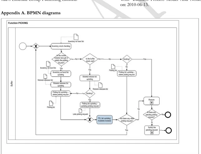
By the way of an example, the FEL generation process as a consequence of a picking request has been represented in BPMN in Fig. 2. In Appendix A more BPMN diagrams are presented.
Figure 2. FEL snapshot: events in a replenishment process represented using BPMN
4. MRP integration
From the BPMN diagrams, which represent the FEL generation procedure as a consequence of a picking request, it should be clear that OPUS simulator embeds a look-back logic for managing material and information flows. As a consequence, OPUS simulator natively manage all the information flows and material handling processes which are based on the attempt of fulfilling any picking
requests coming from entities which are immediately
downstream in the production path: the Master Production Schedule requirements (i.e. which quantity of each finite product item need to be available per each time bucket in a given time horizon) are sent to the finite product stock buffer and, after the fulfilment, the latter
would propagate replenishment requests to the resources upstream in the production path. The stock buffers tend to be filled up to a certain target level and production events are triggered as a consequence of replenishment needs (this is the reason for the expression “look-back”). Having to choose among embedding the look-back or the look-ahead logic when designing the simulator engine operation, the authors opted for the first one. As a consequence, by the way of an example, there is no need to define specific procedures to simulate a Just-In-Time production systems thanks to the fact that the latter is based on a look-back procedure and, thus, it is natively compliant with the OPUS operation logic.
However, in many manufacturing companies, the production progress is based on a Material Requirement Planning (MRP) procedure, which is the typical example of look-ahead logic: the stock buffers tend to be empty and, thus, the requirements tend to flow from the Master Production Schedule up to raw material levels; the operations begins upstream in the production path and production orders are launched only after having computed the appropriate time shifts (according to the forecasted lead times) and the appropriate quantities (according to the lot-sizing rules and to the projected inventory) to fulfil the requirements. MPS is scanned well in advance with respect to the production start, and that is why the procedure is called “look-ahead”.
The introduction of an MRP module on top of a simulation engine aims at providing a more sophisticated tool to support production systems management; in spite of this, given that OPUS is designed to work with look-back logic, the MRP integration was definitely a challenge. Indeed, simulation runs may be used to determine the effects of certain MRP decision parameters (e.g. lot sizing criteria or the presence of given firm planned orders) combined with the randomness of other system variables (procurement lead times, unplanned change-over requirements, unexpected resource breakdowns, sudden increases in scraps, etc.) under specific conditions. Comparison of different additional runs, where stochastic events and variables are properly merged together, may help to determine MRP effectiveness and robustness, as well as to validate the procurement schedule.
Trying to adapt the simulation engine to the MRP procedure, the authors focussed at first on stock buffer operations: indeed, one of the main differences among simulating look-back and look-ahead logic lies in the reaction of the stock buffer to a material request: in the look-back logic, a stock buffer propagates upstream a material request for its replenishment; in the look-ahead logic, the material requests are not propagated by stock buffers and, on top of this, the requested quantities are not related with any replenishment need but with projected future requirements. Thus it is clear that a different behaviour for stock buffers should be modelled in order to integrate MRP: a “flag” field, in the modelling wizard, may indicate whether a certain item (P/N) is managed with a look-back or a look-ahead policy in each buffer. Thus we have at least one flag field per each item in each buffer; the flag field may become a normal
one-byte field in case the user wants to be able to choose among less than eight different stock handling policies: six seemed anyway enough, i.e. two-bin, order level, re-order cycle, re-order up-to-level, min/max levels (Grando, 1996) among the look-back policies, and MRP as the only well-known look ahead policy. Recalling that OPUS simulator inherently implement look-back policies, the main problem was to design an alternative method to propagate information flows for those items that are stored in stock buffers where the “stock handling policy” byte was set to “MRP”.
After having evaluated different alternatives on how to integrate the MRP inside the simulation engine, the authors chose to adopt a separate routine implementing the traditional MRP procedure (Orlicky, 1975) which could run independently from the simulation, having however in input the same data: BoM, MPS, scrap rates, production and procurement lead times, stock levels, etc. As a main difference with the simulation, stochastic variables are not used in the MRP procedure: while, in the MRP, a production lead time is defined as a deterministic value including the average lead time and eventually a management-specified safety time tdet + tsaf, in the
simulation of the same production process the lead time value tran would be computed as a random occurrence on a
probability distribution e.g. a beta distribution with tdet as
the average and its relative standard deviation.
A secondary FEL (called MRP-FEL) is used to record all events generated by the MRP procedure, in advance with respect to the simulation run. When the simulation starts, the simulation engine tries to import all the production orders from the MRP-FEL to the normal FEL, processing it in chronological order. Then, the execution of the simulation - keeping into account stochastic processing time, setup time, waiting time in queue and other random contingencies - allows to evaluate if the MRP is tightly o loosely planned, helping in determining the most correct offsetting of production orders to compute the proper order release dates.
This simulation/MRP integration approach implicitly embeds a resource capacity check thus partially replacing Capacity Requirement Planning (CRP) functions. On top of this, the implementation of a MRP procedure on a simulation tool may easily support pegging procedures, which are used to determine which orders can be satisfied in case of material shortages or limited capacity according to strategic considerations related to customer priorities. Moreover, multiple runs of MRP simulation in accordance to a Design-of-Experiment methodology can easily put in evidence cause-effect relationships among production systems leverages and MRP performance, thus helping in determining the optimal values of safety time parameters.
4. Conclusions
OPUS project proposes a reference framework in order to represent a standard to model the classical dynamics of real production systems. It is embedded in a simulation tool to provide a standard modelling and simulation
language that matches some of the most common requirements of manufacturing SMEs, moreover providing the operating schemes in Business Process Modeling Notation (BPMN), in accordance to the latest market trends in management.
This paper described the efforts of the authors in trying to integrate Material Requirement Planning (MRP)procedure into a simulation tool which was conceived to natively embed look-back material management logic. A solution was found keeping separate the MRP algorithm execution while sharing the input data and merging in the Future Event List the production orders for those items managed with look-ahead policies. The focal points resulted to be the stock buffers, which need to be set up in “MRP mode” or in one of the various “look-back mode” before simulation starts.
At the moment, slightly adjusting the original BPMN representations, an interface between OPUS architecture and the MRP module has been designed for a consequent coding phase. Thus, MRP functions requirements have been identified and the software input tables have been adapted in order to be effectively used by the MRP algorithm.
An enterprise that asks for business process assessment can figure out an opportunity for developing economical and technical indicators as well as a Decision Support System through OPUS. Currently the software kernel (in “command line” version) of the OPUS simulator will be soon available in an open source version for demo use. Thus an open web community will be established in order to facilitate software improvement and to help interoperability on top of reaching a further standardization level. On top of this, a full GUI version will be distributed free of charge to Italian Universities in order to support operations management teaching. In this way, the simulation software, coupled with the proposed reference model, may even play an important role in education.
References
Battista, C., Giordano F., Iannone R. and Schiraldi M. M. (2010). A proposal for a standard framework for simulating and modeling manufacturing systems.
Proceedings of the Sustainable Development: Industrial Practice, Education & Research Conference, Monopoli, Bari (Italy),
2010 September 14-18.
Bodner, D. A. & L. F. McGinnis (2002). A structured approach to simulation modeling of manufacturing systems, Proceedings of the 2002 Industrial Engineering Research
Conference, Georgia.
Grando, A (1996). Produzione e logistica, UTET.
Habchi, G. & Berchet, C. (2002). A model for manufacturing systems simulation with a control dimension. Simulation Modelling Practice and Theory, Vol. 11 (2003) 21–44, 1569-190X.
Harish, C. (1999). An integrated Model for Master Scheduling, Lot Sizing and Capacity Requirements Planning. The Journal of the Operational Research society, 389-399.
Harris, B., Lewis, F. and Cook, D. (2002). A matrix formulation for integrating assembly trees and
manufacturing resource planning with capacity
constraints. Journal of Intelligent Manufacturing, 239-252. Hlupic, V. A. (1999). Guidelines for selection of manufacturing simulation software, IIE Transactions, Vol. 31, No. 1, pp. 21-29.
Hlupic, V., Irani, Z. & Paul, R. J. (1999). Evaluation Framework for Simulation Software, International Journal of
Advanced Manufacturing Technology, Vol. 15, pp. 366-382.
Law, A. A. (1991). Simulation modeling and analysis, McGraw-Hill, ISBN-13: 978-0-07-329441-4, Singapore. Lindeque, P. & Kruger, P. S. (1988). The Design of a Microcomputer Based Simulator for Production Management Training. Computers ind. Engng, Vol. 14, No. 1, pp. 53-62.
Moon, Y. & Phatak, D. (2005). Enhancing ERP system’s functionality with discrete event simulation. Industrial
Management & Data Systems, Vol. 105, No. 9, pp.
1206-1224. Emerald Group Publishing Limited.
Mujtabi, M. S. (1994). Simulation Modelling of Manufacturing Enterprise with Complex Material, Information and Control Flows, International journal of
Computer Integrated Manufacturing, Vol. 7, No. 1, pp. 29-46.
Mula, J., Poler, R. and Garcia J. P. (2006). MRP with flexible
constraints: a fuzzy mathematical programming approach.
Elsevier, 74-97.
Narayanan, S., Bodner, D. A., Sreekanth, U., Govindaraj, T., McGinnis, L. F., Mitchell, C. M. (1998). Research in object-oriented manufacturing simulations: an assessment of the state of the art, IIE Transactions, Vol. 30, No. 9, ISSN: 795-810.
Orlicky, J. (1975). Material Requirements Planning: The New
Way of Life in Production and Inventory Management. McGraw
Hill.
Smith, J. (2003). Survey of the use of simulation for manufacturing system design and operation, Journal of
manufacturing systems, Vol. 22, No. 2, pp. 157-171.
Sun, L. & Spearman, M. L. (2009). Simulation analysis of a multi-item mrp system based on factorial design.
Proceedings of the 2009 Winter Simulation Conference.
** (2010) http://www.omg.org/spec/BPMN/2.0/ - The Object Management Group, Documents Associated With Business Process Model And Notation, Accessed on: 2010-06-13.
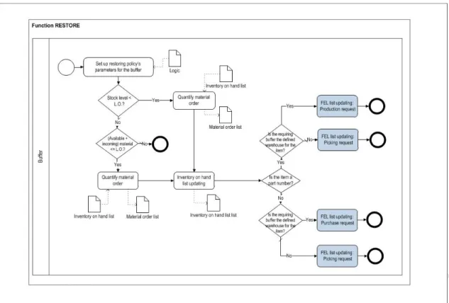
Appendix A. BPMN diagrams