ALMA MATER STUDIORUM - UNIVERSITÀ DI BOLOGNA
SCUOLA DI INGEGNERIA E ARCHITETTURA
(SEDE DI BOLOGNA)
_________________________________________________________________________
CORSO DI LAUREA IN INGEGNERIA INFORMATICA M
A NETWORK FUNCTION VIRTUALIZATION ARCHITECTURE
FOR DISTRIBUTED IOT GATEWAYS
Tesi di laurea in STSTEMI DISTRIBUITI
Relatore Candidato
Prof. Ing. Paolo Bellavista
Luca Montanari Correlatori
Dr. Roch H. Glitho Dott. Ing. Luca Foschini
_________________________________________________________________________
Anno Accademico 2015/2016 Sessione III
Abstract Italiano
La virtualizzazione permette a diverse applicazioni di condividere lo stesso disposi-tivo IoT. Tuttavia, in ambienti eterogenei, reti di dispositivi IoT virtualizzati fanno emergere nuove sfide, come la necessità di fornire on-the-fly e in maniera dinamica, elastica e scalabile, gateway. NFV è un paradigma progettato per affrontare queste nuove sfide. Esso sfrutta tecnologie di virtualizzazione standard per consolidare spe-cifici elementi di rete su generico hardware commerciale. Questa tesi presenta un'ar-chitettura NFV per gateway IoT distribuiti, nella quale istanze software dei moduli dei gateway sono ospitate su un'infrastruttura NFV distribuita, la quale è operata e gestita da un IoT gateway Provider. Considereremo diversi IoT Provider, ciascuno con le proprie marche, o loro combinazioni, di sensori e attuatori/robot. Ipotizzere-mo che gli ambienti dei provider siano geograficamente distribuiti, per un'efficiente copertura di regioni estese. I sensori e gli attuatori possono essere utilizzati da una varietà di applicazioni, ciascuna delle quali può avere diversi requisiti per interfacce e QoS (latenza, throughput, consumi, ecc...). L'infrastruttura NFV consente di effet-tuare un deployment elastico, dinamico e scalabile dei moduli gateway in questo ambiente eterogeneo e distribuito. Inoltre, l'architettura proposta è in grado di riuti-lizzare moduli il cui deployment è stato precedentemente compiuto. Ciò è ottenuto attraverso Service Function Chaining e un'orchestrazione dinamica a runtime. Infine, presenteremo un prototipo basato sulla piattaforma OpenStack.
Abstract
Virtualization enables multiple applications to share the same IoT device. However, in heterogeneous environments, networks of virtualized IoT devices raise new chal-lenges, such as the need for on-the-fly, dynamic, elastic, and scalable provisioning of gateways. NFV is a paradigm emerging to help tackle these new challenges. It leverages standard virtualization technology to consolidate special-purpose network elements on commodity hardware. This article presents NFV architecture for dis-tributed IoT gateways, in which software instances of gateway modules are hosted in a distributed NFV infrastructure operated and managed by an IoT gateway pro-vider. We consider several IoT providers, each with its own brand or combination of brands of sensors and actuators/robots. We assume the providers' environments to be geographically distributed, to efficiently cover extensive physical areas. The sensors and actuators can be accessed by a variety of applications, each of which may have different interface and QoS (latency, throughput, etc.) requirements. The NFV infra-structure allows dynamic, elastic, and scalable deployment of gateway modules in this heterogeneous and distributed environment. Furthermore, the proposed architec-ture is capable of reusing already deployed modules, achieved through service func-tion chaining and dynamic runtime orchestrafunc-tion. We also present a prototype that is built using the OpenStack platform.
Table of Contents
1 Introduction ... 5
2 Context and Motivations ... 7
2.1
Context ... 7
2.1.1 Network Functions Virtualization ... 7
2.1.2 NFV Management and Orchestration ... 9
2.2
Motivations ... 16
2.2.1 Previous Work ... 16
3 Use Case, Requirements and Related Work Evaluation ... 19
3.1
Illustrative Use Case ... 19
3.2
Requirements ... 21
3.3
State-of-the-Art Evaluation ... 23
3.3.1 Traditional Architectures (WSN/IoT Gateways) ... 24
3.3.2 NFV Architectures (Middleboxes) ... 24
4 Proposed Architecture for IoT Gateways ... 29
4.1
Architectural Principles ... 29
4.2
Overall Architecture ... 29
4.2.1 Architectural Modules ... 30
4.2.2 Interfaces ... 34
4.2.3 Control Plane ... 34
5 Implementation and Validation ... 50
5.1
Current Solutions ... 50
5.1.1 Environment Solutions ... 50
5.1.2 Management Solutions ... 54
5.2
Implementation ... 60
5.2.1 Software Architecture ... 60
5.2.2 Setup ... 64
5.2.3 Implementation details ... 64
5.2.4 Validation ... 78
6 Conclusions and Future Work ... 79
Appendix
A References ... 81
5
Chapter 1
Introduction
Research on Internet of Things (IoT) devices virtualization has become prominent in recent years. Virtualization technology abstracts device resources as logical units, and allows for their efficient and simultaneous usage by multiple simultaneous ap-plications, even if they have conflicting requirements and goals. This capability permits to transform a network of IoT devices into a multi-purpose platform, in which several virtual IoT devices are created on demand, each tailored for a specific task or objective. Moreover, IoT devices are heterogeneous by nature, depending on their functionalities, hardware capabilities, and vendor. Consequently, challenges arise when trying to communicate with them in a simple and unique way.
Gateways are required for the interactions between applications and IoT devices. They are generally complex. Furthermore, it is difficult and expensive to upgrade them when new-brand sensors and actuators/robots are deployed. In addition, their capabilities do not scale when the number of applications and the corresponding workload in the IoT devices change dynamically.
Network functions virtualization (NFV) [1] is an emerging paradigm in overcoming the aforementioned challenges. NFV permits standard virtualization technology to consolidate dedicated network elements (e.g., firewalls, network address translation [NAT]) onto commodity hardware. By implementing network functions as software instances called virtual network functions (VNFs), NFV reduces the operational costs and provides hardware independence. Moreover, on-the-fly, dynamic, scalable, and elastic provisioning of network services is among its benefits.
In this thesis, we present an NFV architecture for distributed IoT gateways. The firmware/hardware used to provide IoT gateway functionalities are replaced by VNFs deployed in an NFV infrastructure. We enable granular provisioning of NFV
6
to decompose the gateway into fine-grained modules, such as metadata extractor and information model converter, to be implemented as VNFs. More importantly, granu-lar NFV is best suited, since the dynamic growth in the number of applications and the addition of new-brand sensors require rapid introduction of new VNFs and up-date of the existing ones. VNFs are instantiated on the fly and chained to realize an IoT gateway.
Some providers of IoT devices might not have a centralized environment. Their in-frastructure could be scattered across multiple Points of Presence (PoPs), which are locations where network functions are implemented. Accordingly, it may not be possible to deploy the gateway modules on top of the same PoP. Hence, the need arises for a distributed architecture capable of deploying and managing them on a distributed environment. Moreover, the architecture allows for the reuse of already deployed functions, for cost efficiency purposes. This is achieved through dynamic runtime orchestration. Finally, given the elevated number of possible functions that can be employed to generate a gateway, the architecture provides a way to describe the functions.
The architecture introduces a new business actor — the IoT gateway provider — in addition to the traditional ones, meaning the end user applications and the IoT pro-viders. This new actor plays a dual role. On one hand, it provides two algorithms: one to find and obtain the VNFs, and one to chain them to make on-the-fly gate-ways. On the other hand, it operates and manages the infrastructure in which the VNFs are executed.
The rest of the thesis is organized as follows. In Chapter 2 we discuss the back-ground information and the motivations behind this research. Chapter 3 introduces an illustrative use case, the architectural requirements, and the critical review of the state of the art. In Chapter 4 we present our architecture and its functioning. Chapter 5 first evaluates different solutions for the implementation, then it describes the pro-totype that validates the architecture, along with its implementation details. Chapter 6 concludes the thesis, and outlines the future work to be done.
7
Chapter 2
Context and Motivations
This chapter presents the necessary context information and the motivations behind this research.
2.1 Context
This section presents the background information that is relevant to our research domain. It covers two topics: Network Functions Virtualization (NFV), with a focus on ETSI NFV Management and Orchestration (MANO) and Internet of Things (IoT).
2.1.1 Network Functions Virtualization
NFV is an emerging paradigm that offers a new way to design, deploy and manage network services, by leveraging virtualization technology [2]. The main goal of NFV is the decoupling of network functions from the underlying proprietary hard-ware appliances. This allows for the consolidation of many network equipment types on high volume servers, switches and storage, which could be located in data cen-ters, network nodes and the end-user premises. In NFV, a service can be decom-posed in a set of Virtual Network Functions (VNFs), which are stand-alone pieces of software that can run on one or more infrastructure resources, either physical or vir-tual.
NFV aims at bringing several benefits to Telecommunication Service Providers (TSPs). Some of them are listed below:
8
Reduced equipment cost and energy consumption, achieved by equipment con-solidation.
Reduced development cost and time to market, achieved by decoupling the software from the hardware. This allows network operators to focus solely on the software development.
Reduced CAPEX (Capital Expenses) and OPEX (Operational Expenses), since NFV allows for flexible network function deployment. This means that network operators can deploy new network services over the same physical platform.
Dynamic scaling of the services by need. NFV allows to decouple the function-ality of a network function into instantiable software components. This permits to scale the actual VNF performance more dynamically, with greater flexibility and finer granularity. One example can be VNF capacity provisioning in re-sponse to the actual traffic.
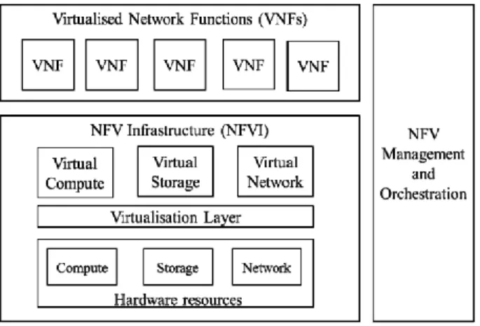
The European Telecommunications Standards Institute (ETSI) Industry Specifica-tion Group for Network FuncSpecifica-tions VirtualizaSpecifica-tion (ISG NFV) has defined a reference architectural framework for NFV [3]. Figure 2.1 illustrates the high-level NFV framework, in which three main architectural components are identified: VNFs, NFV Infrastructure (NFVI), and NFV MANO.
NFVI is the combination of physical and virtualized resources, subdivided in com-pute, storage and networking, that make up the environment in which VNFs are de-ployed, managed and executed. Virtual resources (i.e., compute, storage, and net-work) are an abstraction of the physical ones, this abstraction is achieved using a virtualization layer based on a hypervisor. For instance, the virtual computing and storage resources can be represented in terms of Virtual Machines (VMs).
A VNF is the software implementation of a network function (e.g., firewall, NAT, DHCP) that is deployed on top of NFVI resources, for instance, a VM. A VNF can also be decomposed in its constituent parts, therefore it can be deployed over multi-ple VMs. In the same way, a VM can host multimulti-ple VNFs. The order, number, and
9
type of VNFs constituting a network service is dependent on the functionality and the behavior of the service itself.
NFV MANO covers the orchestration and lifecycle management of VNFs, network services and physical and hardware resources. This component will be further ex-plored in the next paragraph.
Figure 2.1 – High-level NFV framework
2.1.2 NFV Management and Orchestration
The NFV MANO [4] architectural framework has the role to manage the NFVI and orchestrate the allocation of resources needed by the Network Services (NSs) and the VNFs. This level of coordination is necessary, given the decoupling of the net-work functions from their infrastructure.
The management and orchestration of NFVI covers both physical and virtualized re-sources. For the physical ones, the management mainly focuses on connectivity as-pects between physical and virtualized resources. For the virtualized resources, the management aims at handling NFVI resources in NFVI Points of Presence (NFVI-PoPs). A Network PoP is a location where a physical or virtual network function is implemented [5]. Some of the NFVI management operations include: service dis-covery; resource availability, allocation, release; resource fault and performance management.
10
The management and orchestration aspects of VNFs focus on VNF lifecycle opera-tions. Some of these include: VNF instantiation (create a VNF and allocate proper NFVI resources to it), VNF scaling, VNF update and upgrade (support software or configuration changes), VNF termination (release the NFVI resources associated with the VNF).
The scaling operation allows to increase or reduce the capacity of a VNF, in re-sponse to its actual performances. The scale can be either "vertical" or "horizontal". In case of vertical scaling, the management increases or diminishes the VNF compu-tational resources (e.g., CPU, memory). Horizontal scaling means that the manage-ment can instantiate (respectively terminate) multiple instances of the same VNF so that the workload can be split between them.
Another important aspect of the VNF Management is the monitoring of the Key Per-formance Indicators (KPIs) of a VNF, mainly for scaling purposes. For instance, if the incoming traffic through a VNF is too high, the VNF Management might scale up the VNF to increase its capabilities and avoid a possible bottleneck in the net-work.
The Network Service Orchestration focuses on the management of the lifecycle of Network Services. Some of the operations include: NS registration, instantiation, scaling (grow or reduce the capacity of the NS), update (service reconfiguration such as changing inVNF connectivity or the constituent VNF instances) and ter-mination.
The NS Orchestration manages the lifecycle of VNFs that realize an NS and it per-forms its services by using the VNF Management services and by orchestrating the NFV Infrastructure in which the VNFs run.
11
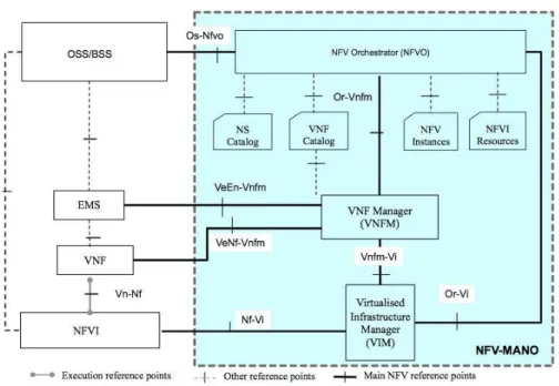
Figure 2.2 – NFV MANO architecture
Figure 2.2 shows a detailed view of the NFV MANO architecture, with all its com-ponents and reference points. For the purposes of this thesis it is only important to note that the NFV Orchestrator (NFVO) covers the functionalities of the Network Service Orchestration and it is responsible for the orchestration of NFVIs across multiple VIMs. The VNF Manager (VNFM) covers the management and orchestra-tion aspects of VNFs. The Virtualized Infrastructure Management (VIM) is respon-sible for the management of the NFVI resources.
2.1.3 Internet of Things
The following section will introduce the IoT, a novel paradigm that extends Internet to real world things, such as physical devices, vehicles, and buildings. The first part will provide an overview on IoT, its enabling technologies and its possible applica-tions. Then, a high level architecture of IoT is presented. The last part will introduce the IoT middleware, its architecture, and current solutions for it.
12
2.1.3.1 Overview and Enabling Technologies
IoT is considered as part of the internet of the future. Its basic idea is to allow con-nection and exchange of data between real world devices, called things, and applica-tions. The IoT bridges real life and physical activities with the virtual world [6]. The IoT devices comprise sensors, Radio Frequency Identification (RFID) tags, Near Field Communication (NFC) tags, actuators, mobile phones, etc. These devices have certain unique features. They are uniquely identifiable and accessible to the Internet and are able to interact with each other and cooperate to achieve common goals [7]. IoT applications can be present in a variety of fields in our daily life. Possible exam-ples can be smart home design, environment monitoring and natural disasters predic-tion, intelligent transport systems, smart cities design, medical and industry applica-tions, etc.
The IoT concept can be realized by several enabling technologies. One example is identification, sensing and communication technologies such as RFID tags that are characterized by a unique identifier and sensor networks that are composed of sever-al nodes communicating in a wireless multi-hop fashion. IEEE 802.15.4 is a widely adopted standard for wireless sensor networks. It defines the physical and MAC lay-ers for low-power, low bit rate communications in wireless play-ersonal area networks (WPAN).
At the application layer, the Constrained Application Protocol (CoAP) has been in-troduced. It is a specialized internet protocol for constrained nodes and networks in the IoT. It allows for communication between these constrained devices and general nodes on the Internet. CoAP is designed to be easily translated to HTTP for faster integration with the web. Like HTTP, it is based on the Representational State Transfer (REST) model: Servers make resources available under a URL and Clients access them using HTTP methods such as GET, PUT, POST and DELETE. CoAP is designed to be extremely lightweight. To achieve this, at the transport layer it uses UDP on top of IP. Moreover, messages have a 4-byte header and a compact encod-ing of options to minimize fragmentation at the link layer.
13
A basic simplified workflow of IoT can be described as follows: some RFID tags can be sensed by smart sensor devices which will then send the retrieved infor-mation over the internet to a computational or processing unit. The data is then pro-cessed and the result is passed to a decision making and action invoking system. This system determines an automated action to be executed, for example, on an ac-tuator or a robot.
2.1.3.2 IoT Architecture
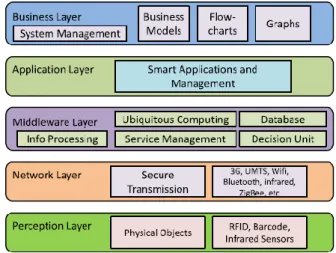
The architecture of IoT is generally divided into five layers, as shown in Figure 2.3:
Perception or Device Layer. This layer consists of the physical objects or sen-sors, which mainly have identification or sensing purposes. The collected data is passed to the Network layer for secure transmission to the information pro-cessing system.
Figure 2.3 – IoT architecture
Network or Transmission Layer. This layer transfers information from sensor devices to information processing systems, thus bridging the perception layer with the Middleware layer. The transmission medium can be either wired or wireless, depending on the devices. Depending on the sensor device, the trans-mission technology can be 3G, Wi-Fi, Bluetooth, ZigBee, infrared, etc.
14
Middleware Layer. IoT devices can connect and communicate only with other devices that implement the same service type. This layer is responsible for ser-vice management. The other role of the Middleware layer is to receive infor-mation from the Network layer, store it into a database, process it and take au-tomatic decisions based on the results.
Application Layer. This layer is responsible for the global management of the application based on the processed data obtained from the Middleware layer. Possible IoT applications can be smart home, smart city, smart health, etc.
Business Layer. This layer manages the overall IoT system, including applica-tions and services, based on the data received from the Application layer.
Given the growth of IoT popularity in research, industry, and government, many standardization efforts are being carried and many international organizations are involved in the development of IoT. For instance, the Internet Engineering Task Force (IETF) introduced the IPV6 over Low-Power Wireless Personal Area Net-works (6LoW-PAN) which defines a set of protocols that can be used to integrate sensors nodes into IPV6 networks.
2.1.3.3 IoT Middleware
Another example of IoT concept realization is the middleware, which is a software layer positioned between the technological and the application levels. It hides the heterogeneity of IoT devices and communication technologies. Therefore, a pro-grammer is exempted from the exact knowledge of the underlying technologies while developing IoT applications. IoT middleware also simplifies the integration of legacy technologies with the new ones.
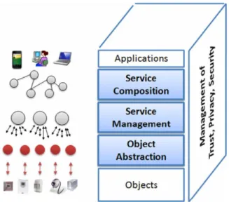
IoT middleware architectures proposed in the last years often follow the Service Oriented Architecture (SOA) approach. It allows for the decomposition of complex and monolithic systems into applications consisting of simpler and well-defined components. Architectures following the SOA approach have five layers (Figure 2.4):
15
Applications are on top of the architecture, they exploit the functionalities of the other layers and provide it to the end-user.
The service composition layer provides the functionalities for the composition of different services by networked objects to build specific applications.
The service management layer provides functionalities such as object discovery, status monitoring, and service configuration. It enables the remote deployment of new services during run-time to meet the application requirements. The upper layer can then compose complex services by joining the ones provided at this layer.
Figure 2.4 – SOA-based architecture for IoT middleware
The object abstraction layer provides an abstraction of the heterogeneous IoT devices by harmonizing the access to them. This is done through offering com-mon languages and procedures.
The trust, privacy, and security management layer provides functionalities relat-ed to the security and the privacy of the exchangrelat-ed data.
Popular solutions for IoT middleware include:
Oracle Fusion Middleware [8]. It is an open source, comprehensive middleware that spans across multiple services, such as cloud applications, service
integra-16
tion, business intelligence, performance management, etc. The services imple-mented for the IoT middleware include real-time analysis (with a module specif-ically built for IoT gateways), device and service integration (using an SOA ap-proach), security and monitoring.
WSO2 Middleware platform [9]. It is an open source, SOA-based middleware that provides API management, integration and analytics offerings. It also has a focus on mobile and IoT.
MachineShop [10] is an API-centric platform for enterprise IoT. It delivers a services-based architecture allowing the user to create and manage its own APIs. It leverages the REpresentational State Transfer (REST) API for interaction be-tween components.
Red Hat JBoss Middleware [11]. It is a complete and open source middleware that focuses on business process automation, system integration and accelerated development.
2.2 Motivations
Recently, a research effort has been conducted to solve the issue that emerges when heterogeneous applications want to communicate with heterogeneous IoT devices. This section briefly presents the work, its characteristics, and what has accom-plished. However, that work suffers from various limitations. Therefore, in this the-sis a new architecture is proposed to address them.
2.2.1 Previous
Work
IoT devices (i.e., sensors and actuators) are very heterogeneous by nature. In fact, different devices may belong to different providers and have different hardware and/or capabilities. This raises a challenge when multiple and heterogeneous appli-cations need to communicate with these multivendor IoT devices. In order for these
17
heterogeneous IoT devices to interact with the applications, there is need for gate-ways to support these interactions.
A gateway architecture has been proposed in [12] to solve the aforementioned chal-lenge. The proposed architecture is based on NFV. It decomposes the gateway into fine-grained modules (e.g. protocol converter, information model converter) imple-mented as VNFs and deployed in an NFV infrastructure.
The architecture satisfies the following requirements:
The gateway supports standard northbound and proprietary southbound
inter-faces. One example of standard northbound interface could be the widely
adopt-ed Sensor Markup Language (SenML), carriadopt-ed over HTTP. It is designadopt-ed to en-code sensor measurements and device parameters.
The architecture is extensible, elastic and scalable. Extensibility means that the architecture supports the introduction of new applications and domains. Elastici-ty allows for efficient utilization of underlying physical resources. Finally, scalability promotes the increasing amount of applications.
The NFV architecture is flexible enough to support the integration of sensors from various brands.
The overall functioning can be summarized as follows: an end-user application re-quests services of sensor and/or actuator belonging to a Virtualized Wireless Sensors and Actuators Networks (VWSAN) Provider. The application provides the descrip-tion of its northbound interface. Accordingly, the VWSAN Provider finds the proper sensor, retrieves its southbound interface description and sends a VNF request con-taining the description of the northbound and southbound interface description to a Gateway Provider. The Gateway Provider retrieves the VNFs necessary to compose the requested gateway, chains them, and migrates them as a whole package to a cen-tralized location in the VWSAN Provider domain. Finally, the VWSAN Provider notifies the end-user application on the service availability. The application can now interact with the sensors through the provided gateway.
18
This approach has mainly two limitations. The first one is that the architecture as-sumes the VWSAN as a centralized domain. This might not be the case, as a VWSAN may be distributed across multiple locations. The second one is that com-pletely new gateways are dispatched each time a new brand of sensors and/or actua-tors is deployed. This could lead to cost inefficiencies, because some of the services that compose the new gateway might already be present in the VWSAN domain.
19
Chapter 3
Use Case, Requirements and Related
Work Evaluation
This chapter introduces an illustrative scenario and the set of requirements derived from it. After that, the state-of-the-art is reviewed in sight of these new require-ments.
3.1 Illustrative Use Case
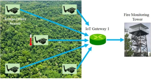
Over the last few years, the occurrence of large-scale wildfire episodes with extreme fire behavior has affected different regions of Europe: Portugal (2003 and 2005), south-eastern France (2003), Spain (2006 and 2009), and Greece (2000, 2007, and 2009). In such cases, continuous monitoring of a fire outbreak within fire-prone are-as is critical. The monitoring can be done through IoT devices such are-as sensors scat-tered throughout a forest, and all linked back to a disaster management application (Figure 3.1). These sensors can be of various capabilities including temperature, humidity, rain gauge, CO2 detectors, and wind speed sensors. When a fire is broken out, the sensors inform the disaster management application (Figure 3.2). The appli-cation then dispatches rescue robots as another type of IoT device (Figure 3.3). In order to collect measurements from the sensors and send commands to the robots in a heterogeneous environment, a gateway is needed for the interactions between the application and these IoT devices. These gateways implement functions such as pro-tocol converter, information model converter, data analytics, etc.
20
Figure 3.1 – Forest Monitoring
Figure 3.2 – Fire Outbreak
21
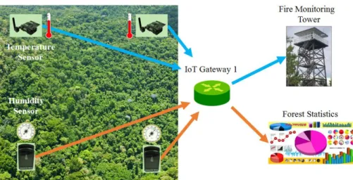
Figure 3.4 – Deployment of Different Applications and Sensors
In some cases, new brand of IoT devices or new applications may join and use the same protocol used by an already deployed IoT device or an application. Let us con-sider an environment where Preon32 sensors from Virtenio [13] and TelosB sensors from Advanticsys [14] have been deployed. Both can employ the CoAP protocol for communications. If an application (using HTTP) wants to collect data from them, a protocol conversion function must be used for the communication. Since both brands employ CoAP, the same protocol conversion function can be exploited. Ac-cordingly, one function (e.g., protocol converter) may belong to different flows cor-responding to different gateways (Figure 3.4).
3.2 Requirements
In order to address the limitations of the previous work [12], the architecture must be redesigned in order to satisfy the following requirements:
Discovery of the required functions for a given application. In the previous work, a gateway was requested by simply providing a description of the north-bound and southnorth-bound interfaces. This description is no longer sufficient be-cause the range of available gateway modules is wide and diverse. For example, a metadata extractor, while being dependent from a particular IoT device, cannot be demanded by only providing the southbound interface description. Instead, a
22
specific request must be made. Consequently, more information is needed in or-der to find the proper gateways. This information regards the functions to use, but could also cover characteristics of the deployment environment, latency, en-ergy consumption, etc.
Finer granularity of deployment. The micro-services that implement a gateway must be deployed separately and not as a package. Also, the architecture should allow for the reuse of an already deployed function. In the previous architecture, a brand new gateway was dispatched each time an application requested one. All the micro-services composing the gateway were deployed, as a package, even if some of them were already provisioned in the environment. In order to avoid cost inefficiencies, it is necessary to deploy each function separately and to im-plement a mechanism capable of checking if the functions are already available. Currently, gateway are often deployed on dedicated hardware, and in most solu-tions they are not split into their composing funcsolu-tions. On the other hand, NFV allows for the deployment of single functions, but there are currently no solu-tions that address IoT gateways.
Finer granularity of management. The management of the gateway modules should be flexible enough to cope with the fact that the same function could be-long to different execution flows. Accordingly, each flow may need to be man-aged in a specific manner corresponding to the application it belongs to. As an example, let us consider a gateway function used both by a fire monitoring ap-plication and a data analytics apap-plication. For the first apap-plication, low latency must be guaranteed at all times, while for the second one, the requirements might be less stringent. Consequently, the function must be managed in different ways, depending on the application it belongs to. If we consider the gateway modules as VNFs, many solutions have been proposed for their management. However, most of these do not provide a way to define custom sets of policies and operations.
23
Dynamically orchestrating the flow when executing the gateway modules. The execution flow of the gateway must not be hard coded, instead it should be de-termined at runtime. In the previous work, the gateways were deployed as a package, therefore, the routing was implemented in a hard coded and static way. However, now there is need to reuse the already deployed functions, when pos-sible. This means that the execution of the gateway cannot be hard coded. The introduction of the Service Function Chaining (SFC) paradigm can be of great aid to address the requirement. Some possible architectures will be presented in the next section, although none of them will provide a comprehensive solution that can cover the other requirements as well.
3.3 State-of-the-Art Evaluation
The illustrative scenario presented the possible use of IoT devices in large-scale wildfires and demonstrated the need for IoT gateways, for proper interaction be-tween the IoT devices and the applications using them. In the state of the art for WSN/IoT gateway architectures, the main focus has been on bridging different sen-sor domains with public communication networks and the Internet.
Also, the existing literature describes a growing trend in NFV-based middlebox de-sign. Since an IoT gateway falls under the taxonomy of middlebox, a brief overview of NFV architectures within the context of middleboxes is relevant.
The literature overview on current management and orchestration solutions will cover NFV MANO and SFC architectures. SFC is a novel paradigm introduced to address dynamic service composition and orchestration.
Therefore, the state-of-the-art is classified into three categories: Traditional architec-tures (WSN/IoT gateways), NFV architecarchitec-tures (middleboxes), and management and orchestration architectures (NFV MANO and SFC).
24
3.3.1 Traditional Architectures (WSN/IoT Gateways)
An architecture for an in-home IoT gateway is proposed in [15]. It consists of three subsystems: sensor node, gateway, and application platform. The gateway is de-ployed as a package on top of dedicated hardware, so it does not allow for the reuse of an already deployed component.
Jiang et al. [16] present an IoT gateway architecture for a CorbaNet-based digital broadcasting system, designed to lessen the effects of IoT technology on backbone networks. However, the gateway is considered as a monolithic block so it cannot be distributed.
A configurable, multifunctional, and cost-effective architecture for smart IoT gate-ways is proposed in [17]. It is possible to plug different modules into the architec-ture and the gateway can be dynamically configured. Dynamic flow orchestration is not discussed.
In [18], the authors propose an IoT gateway-centric architecture that provides vari-ous M2M services, such as association of metadata to sensor and actuator measure-ments using SenML. The gateway functionalities are hard-coded so finer granularity of deployment is not supported.
In [19], a gateway architecture for home and building automation system is pro-posed. The gateway is managed remotely by the network operator. However, reusa-bility of already deployed functions is not discussed.
3.3.2 NFV Architectures (Middleboxes)
ClickOS [20] is a Xen-based software platform that allows hundreds of middleboxes to run on commodity hardware. It includes both simple middleboxes (e.g., packet forwarding from input to output interfaces) and full-fledged middleboxes (e.g., IPv4 router, firewall, etc.). However, virtualization of IoT gateway modules is not inves-tigated.
25
T-NOVA [21] is an integrated architecture that enables network operators and ser-vice providers to manage their NFVs. It provides VNFs, like flow handling control mechanisms, as value-added services to its customers. T-NOVA allows third party developers to publish their VNFs as independent entities. Dynamic flow orchestra-tion is not discussed.
In [22], NFV is used to virtualize an IP telephony function called Session Border Controller (SBC), which operates on both the control plane (i.e., load balancing and call control) and the media plane (i.e., media adaptation capabilities). The architec-ture is flexible and scalable.
The use of NFV for the virtualization of routing functions in OpenFlow-enabled networks is explored in [23]. All these works do not target the IoT domain.
3.3.3 Management and Orchestration Architectures
In [24], ETSI proposes a hierarchical MANO architecture composed by an umbrella NFVO and several administrative domains. The architecture is based on NS decom-position in which a NS is split in its sub-services. Each administrative domain man-ages the NSs that are part of its domain. The umbrella NFVO manman-ages the whole NS. However, it is just a high level overview and no implementation is provided. TeNOR [25] is a core component of the T-NOVA architecture. It allows for auto-mated deployment and configuration of services. The architecture is based on micro-services. VNFs can be deployed over multiple PoPs. The NSs are defined through descriptors, therefore dynamic orchestration is not supported.
Kataoka et al. present DiNO [26], an architecture for distributed NFV deployment. Hypervisors, VNFs, and network equipment can be deployed in an incremental and distributed manner. The architecture supports dynamic allocation of VNFs based on resource state and Service Level Agreement (SLA) monitoring. It also provides a built-in VNF load balancer. Function discovery and dynamic orchestration are not addressed.
26
In [27] the authors propose a Virtual Network Platform-as-a-Service (VNPaaS) for network services. The architecture focuses on distributed life cycle management of NSs and VNFs across geographically distributed locations. Moreover, the system al-lows for service decomposition and distributed management and orchestration. However, the architecture does not support dynamic orchestration.
Vilalta et al. [28] present an architecture for Software Defined Networks (SDN) / NFV orchestration for 5G services. They propose a hierarchical SDN orchestrator and virtualized function orchestration at the edge of the network. Although the work takes IoT into account, finer granularity of management is not discussed.
VLSP is a Service-Aware Virtualized Software-Defined Infrastructure proposed in [29]. The architecture is distributed, hierarchical and scalable. It is SDN-based. However, automated function discovery is not addressed and the work does not take into account the IoT domain.
[30], [31] and [32] propose policy-based or policy-driven architectures for dynamic service chaining and orchestration. These works focus on the composition of ser-vices based on user-defined SLA policies. They don't address service definition. Martini and Paganelli present a Service-Oriented Approach for dynamic chaining of VNFs [33]. Key feature of this architecture is that services are defined at an abstract level and their concrete implementation is derived according to QoS-based utility functions. However, finer granularity of management is not discussed and the IoT domain is not considered.
27
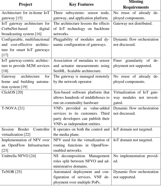
Table 3.1 gives an overview of the solutions analyzed. For each project, the "Key Features" summarizes its main characteristics, while the limitations and drawbacks are addressed in the "Missing Requirements".
Table 3.1 – Summary of the related work
Project Key Features Missing
Requirements Architecture for in-home IoT
gateway [15]
Three subsystems: sensor node, gateway, and application platform.
No reuse of already de-ployed components.
IoT gateway architecture for
CorbaNet-based digital
broadcasting system [16]
The architecture lessens the effects of IoT technology on backbone networks.
Gateway not distributed.
Configurable, multifunctional and cost-effective architec-ture for smart IoT gateways [17]
Pluggability of modules and dy-namic configuration of gateways.
Dynamic flow orchestration not discussed.
IoT gateway-centric architec-ture to provide M2M services [18]
Association of metadata to sensor and actuator measurements using SenML. Scalable architecture.
Finer granularity of de-ployment not supported.
Gateway architecture for
home and building automa-tion system [19]
The gateway is managed remotely by the network operator.
No reuse of already de-ployed components.
ClickOS [20] Xen-based software platform that
allows hundreds of middleboxes to run on commodity hardware
Virtualization of IoT gate-way modules not investi-gated.
T-NOVA [21] VNFs provided as value-added
services to its customers. Third party developers can publish their VNFs as independent entities.
Dynamic flow orchestration not discussed.
Session Border Controller virtualization [22]
It operates on both the control and the media plane.
IoT domain not targeted. Implementation of NFV over
an OpenFlow Infrastructure [23]
NFV used for the virtualization of routing functions in OpenFlow-enabled networks.
IoT domain not targeted.
Umbrella NFVO [24] NS decomposition. Management
roles split between NFVO and ad-ministrative domains.
No implementation provid-ed.
TeNOR [25] Automated deployment and
con-figuration of services. VNF de-ployment over multiple PoPs.
Dynamic flow orchestration not supported.
28
DiNO [26] Distributed NFV deployment.
Dy-namic allocation of VNFs based on resource state SLA monitoring.
Function discovery and dy-namic flow orchestration not supported.
VNPaaS for network services [27]
Distributed management and or-chestration of NSs and VNFs across geographically distributed locations. Service decomposition.
Dynamic flow orchestration not supported.
Architecture for SDN / NFV orchestration for 5G services [28]
Hierarchical SDN orchestrator. Virtualized function orchestration at the edge of the network.
Finer granularity of man-agement not discussed.
VLSP [29] SDN-based architecture.
Distribut-ed, hierarchical and scalable.
Function discovery and IoT domain not targeted.
Policy-based or policy-driven
architectures for dynamic
SFC [30] [31] [32]
Composition of services based on user-defined SLA policies.
Service definition not ad-dressed.
Service-Oriented Approach
for dynamic chaining of VNFs [33].
Services defined at an abstract lev-el. Concrete implementation de-rived according to QoS-based utili-ty functions.
Finer granularity of man-agement not discussed. IoT domain not targeted.
We conclude that, with the exception of limited support for gateway modules, the existing IoT gateway architectures fall short of satisfying the requirements. With re-gard to NFV-based solutions, the current NFV architectures for middleboxes allow for finer granularity of deployment. However, they focus primarily on network ele-ments, e.g., firewall, proxies, and NATs. NFV MANO and SFC architectures allow for finer granularity of management and/or dynamic service orchestration, but al-most no solutions are provided for IoT gateways.
29
Chapter 4
Proposed Architecture
for IoT Gateways
In this chapter, we present our NFV-based IoT Gateway architecture. The architec-tural principles are discussed first, followed by the architecarchitec-tural modules, interfaces, control plane, and an end to end scenario.
4.1 Architectural Principles
Our first architectural principle is the use of NFV concept when designing the IoT gateway. The gateway modules are then implemented as VNFs. NFV brings agility, flexibility, and dynamicity by decoupling network functions from the underlying hardware. The second principle is that the interaction interfaces between different domains are REpresentational State Transfer (REST)-based. REST is selected be-cause it is lightweight, standard-based, and can support multiple data representations (e.g., plain text, JSON, and XML).
4.2 Overall Architecture
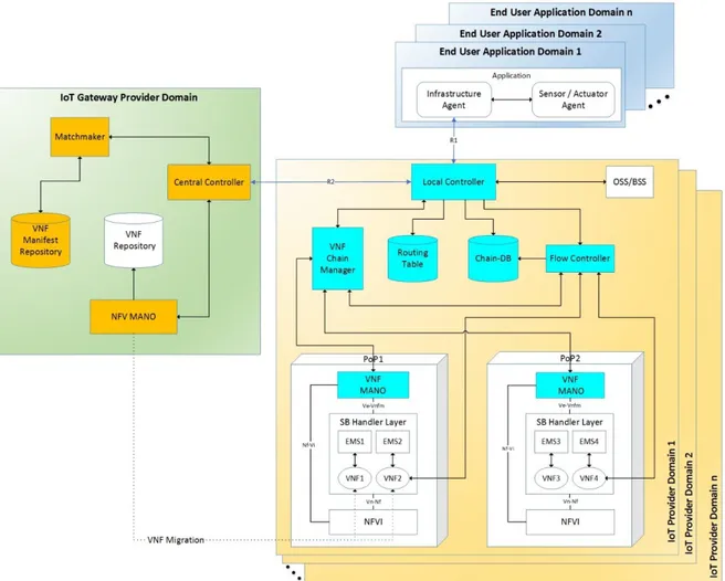
Figure 4.1 shows the proposed architecture. It extends the VWSAN Gateway archi-tecture proposed in [12]. Some new modules have been introduced and some mod-ules have been extended. This is done in order to support the description and the dis-covery of the VNFs required by the application and to support the management of the gateway modules.
30
The architecture comprises several Application Domains, IoT Provider Domains, and an IoT Gateway Provider Domain. The modules and interfaces are presented, followed by the control plane.
4.2.1 Architectural
Modules
Each Application Domain contains an Application that requires the services of one or more IoT Providers. The Application contains two modules: Infrastructure Agent and Sensor/Actuator Agent. The Infrastructure Agent is responsible for the signaling procedure. It communicates with the IoT Provider Domain to negotiate the use of an IoT infrastructure. The Sensor/Actuator Agent is responsible for gathering meas-urements from the sensor and sending commands to the robots.
31
The IoT Gateway Provider Domain consists of the following entities:
Matchmaker: It is a novel module that receives the VNF discovery requests and performs a matchmaking procedure between the requested VNFs and the ones published in the VNF Manifest Repository. It then returns the list of the discovered VNF Manifests.
VNF Manifest Repository: An XML based repository containing VNF Mani-fests of the published VNFs. In the published VNF Manifest the information in-cludes description, function (e.g., a keyword used for publication/discovery pur-poses), image location (endpoint and/or download link), list of operations with related list and type of inputs, outputs, constraints and properties, list of VM re-quirements, list of management operations and related signatures.
NFV MANO: This module has been extended such that the VNFs are not provi-sioned as a package anymore (i.e., the two VNFs at the same time). It enables for finer granularity of deployment/management; dispatching functions instead of packages. The module receives the list of VNFs to instantiate, it accesses the NFVI of the target IoT Provider and checks if the VNFs are already deployed in it. If not, the module downloads the VNFs from the VNF Repository, using the image location tag contained in the VNF Manifests, instantiates them, and then migrates them to the target domain. The module returns to the Central Controller the list of the VNF Instance IDs. The VNF Instance ID uniquely identifies the VM that is hosting a VNF. We assume that each VNF is deployed over one VM.
VNF Repository: The VNF Repository contains the images of the published VNFs. It is accessed by the NFV MANO.
Central Controller: The Central Controller has been extended in order to build the VNF chain (e.g., define the order in which traffic traverses the VNFs). It then sends the VNF Manifests and the VNF Instance IDs in proper order to the Local Controller in the IoT Provider Domain.
32
Each IoT Provider Domain comprises the following modules:
Southbound (SB) Handler Layer: Contains VNFs that have been migrated from the IoT Gateway Provider Domain and their corresponding Element Man-agement Systems (EMS). Each EMS is responsible for monitoring the resource utilization of its corresponding VNF [3].
NFVI: Provides hardware and software resources, including computation, stor-age, and networking needed to deploy, manstor-age, and execute VNFs.
Operational Support System/Business Support System (OSS/BSS): Provides the description of IoT devices (e.g., sensor/robot brands).
Local controller: Interacts with the Infrastructure Agent and the Central Con-troller. It has been extended by adding three new functionalities:
1) Creating VNF discovery requests in the form of VNF Manifest files. A VNF Manifest contains basic VNF information and its structure is defined by an XSD file. In the requested VNF Manifest the information includes function, list and type of inputs and outputs (if any) and eventually a list of the capabil-ities of the hosting node. The data is derived by the information of the north-bound interface used by the application (i.e., communication protocol, infor-mation model, etc.) and the inforinfor-mation of the southbound interfaces used by the IoT devices (i.e., type of sensors/robots).
2) Adding entries to the Chain-DB and to the Routing Table, after receiving the VNF chain from the Central Controller.
3) At runtime, orchestrating the overall communication between the modules.
VNF Chain Manager: Its role is to execute management operations that require a view of the whole system (monitoring total service time, VNF migration, etc.). Also, it has been extended such that it instructs the VNF MANOs on the specific VNF operations they have to execute.
33
VNF MANO: A new module. The VNF MANOs are in charge of monitoring and executing specific operations on the VNFs. There is one VNF MANO per PoP, so the management is geographically close to its respective VNFs. VNF MANOs also need to notify the VNF Chain Manager when the state of a VNF changes (e.g., a VNF scales, or a VNF is no longer working) so that the Chain Manager can in turn notify the Local Controller to make appropriate changes to the tables.
Flow Controller: it is a new module introduced in order to execute and manage the runtime traffic flows. It accesses the Chain-DB to retrieve the chains and communicates with the VNF Chain Manager to obtain the VNF addresses.
Routing Table: This table is introduced in order to bind a VNF to the VM that is hosting it. The VNF is represented by its Manifest and the VM by the VNF Instance ID. The key of this table is the pair "VNF Manifest-VNF Instance ID", while the value is a VNF Unique IDentifier (UID). The VNF UID uniquely identifies a VNF inside the IoT Provider Domain. The VNF Manifest is not suf-ficient by itself because there might be multiple VNFs with the same Manifest (e.g., a scaled VNF) and the VNF Instance ID is not sufficient either, because a VM might host multiple VNFs. The pair is in fact the only way to grant unique-ness and allows to represent a specific VNF with a unique identifier. This UID is also used to define the VNF in the Chain-DB. Entries in this table are added and updated by the Local Controller. An update may occur, for instance, in case of scaling or migration. Table 4.1 shows an example.
Table 4.2 – Routing Table
VNF Manifest – VNF Instance ID VNF UID
ProtocolConverter.xml – 0123-0000 01
InfoModel.xml – 0123-1111 02
34
Chain-DB: It is a new database. It contains all the active chains in the IoT Pro-vider domain. The database is structured as a key-value pair table. The key is a Chain-ID, while the value is the list of VNF UIDs. Table 4.2 shows an example of the database. Table 4.3 – Chain-DB Chain-ID Chain 0000 03 – 01 – 02 0001 02 – 01 0002 03 – 05 – 07 – 03
4.2.2 Interfaces
The NFV components (i.e., NFVI, VNF MANO, SB Handler Layer) interact with each other through the interfaces defined by ETSI [3]. They include Vn-Nf, Nf-Vi, and Ve-Vnfm. Vn-Nf represents the execution environment provided by NFVI to SB Handler Layer. Nf-Vi is used for assigning virtualized resources in response to re-source allocation requests (e.g., allocating VMs on hypervisors). It is also used by NFVI to communicate status information about virtualized and hardware resources to the VNF MANOs. Nf-Vi is also used to configure hardware resources. Ve-Vnfm carries out all operations during a VNF life cycle, including instantiation, scaling, updating, and termination. It is also used for exchanging VNF configuration infor-mation.
4.2.3 Control Plane
35
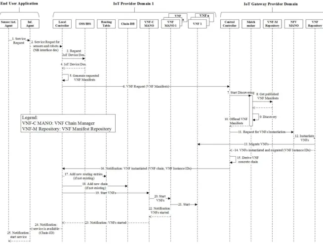
4.2.3.1 Signaling Procedure (Figure 4.2)
The signaling is initiated when the application requires services from the IoT Pro-vider Domain. The Sensor/Actuator Agent instructs the Infrastructure Agent to start service negotiation. The Infrastructure Agent creates a service request that includes a description of the northbound interface (action 2) used by the application (e.g., communication protocol, information model, etc.) and sends it to the Local Control-ler of the IoT Provider Domain.
Figure 4.6 – Signaling Procedure Sequence Diagram The signaling procedure includes several phases:
1) Describing the functions for a given application (action 5)
The process is initiated by the Local Controller when it receives the service request from the application. Upon receipt of this request, the Local Controller
communi-36
cates with the OSS/BSS (action 3-4) to obtain information on parameters specific to the IoT devices it has (e.g., type of sensors/robots). It then creates a description of the functions needed in the form of VNF Manifest files. The Local Controller then sends to the Central Controller in the IoT Gateway Provider Domain a VNF Request containing the VNF Manifests (action 6).
2) Discovering the required functions for a given application
Once the matchmaker receives the VNF discovery requests (action 7), it first gets the list of published VNFs manifests from the VNF Manifest Repository (action 8), then it starts a matching procedure between the requested VNFs manifests and the published/offered ones (action 9). Figure 4.3 shows a flowchart of the process, which is done in three steps:
Figure 4.7 – Flowchart of Matchmaking Procedure
a) The first match is done using the <function> element. This element is present in both Request and Offer manifest files and contains a keyword that identifies the function (Figure 4.4).
37
b) If the match succeeds, then the matchmaker will compare inputs and outputs of the various operations. At this stage, a specific rule is applied: if the Request specifies any inputs or outputs, the Offer must match number, format, and type (Figure 4.5).
Figure 4.8 – Function Name Match
Figure 4.9 – Input & Output Match
The <constraints> tag is an optional tag that follows the inputs. It defines restrictions that might apply to certain input values. There is no general rule of comparison since these constraints might be of various nature, so they are evaluated case by case. The same criteria apply for the <properties> tag, which is instead related to the outputs. Figure 4.6 shows an example where an offered function takes two values as input, either integer or double. A constraint states that these two values must be of the same type. The Request Manifest requires an operation that takes a double and an integer as inputs. Although the Request inputs are compatible with the ones in the Offer, they don't satisfy the constraint, since they are of different type. Therefore, the match fails.
38
c) The last step will require comparing the Offer requirements (if any) with the Request capabilities. The requirements are the environmental properties necessary to execute a VNF (e.g., CPU, memory, software installed), while the capabilities are the current properties of the IoT Provider domain. The match can be exact (=), min-imum (≥), or maxmin-imum (≤) (Figure 4.7).
Figure 4.10 – Constraints Evaluation
Figure 4.11 – Requirements & Capabilities Match
If the number of offered Manifests obtained is equal to the number of the requested ones, the overall procedure succeeds and the offered VNF Manifest are returned to the Central Controller. If the procedure fails, a notification of VNF unavailability is sent by the Central Controller to the Local Controller
39
In case of multiple matching for the same request, different choices can be adopted, depending on the Gateway Provider implementation. For example, the matchmaker can return the VNF with the least computational needs or latency. Or it can return the VNF that has the most number of operations. In our case, for simplicity reasons, we will adopt the "first matching" rule: only the first VNF that fulfills the matching gets returned.
Once the offered VNF Manifest are obtained (action 10), the Central Controller re-quests the NFV MANO in the IoT Gateway Provider Domain to instantiate and mi-grate the VNFs (action 11). The NFV MANO first checks if the VNF are already in-stantiated in the target domain, then it proceeds to instantiate and migrate the ones missing (action 13), after getting them from the VNF Repository (action 12).
The NFV MANO returns to the Central Controller the list of the VNF Instance IDs (action 14). These are unique identifiers for the VMs containing the VNFs.
3) Chain creation in the Central Controller
The Central Controller maintains a file that contains pre-built, abstract chains. These abstract chains can be provided by the VNF publishers or by the IoT Gateway Pro-vider itself, since it knows the services it is offering (i.e., the gateways). An abstract chain defines a service at an abstract level, this way the elements comprising it are not bind to any specific implementation. One possible file format can be as follows, with one chain per line:
ProtocolConversion-InfoModelCoversion
DataAnalysis&Aggregation-MetadataExtraction-ProtocolConversion-InfoModelCoversion MetadataExtraction-InfoModelConverison-ProtocolConversion
Each element in an abstract chain corresponds to a <function> element of a VNF manifest.
Once all the VNF Manifests are received from the matchmaker, the Central Control-ler derives the concrete chain (action 15).
40
A concrete chain is the actual implementation of an abstract chain, in which all the elements are bind to the instantiated VNFs. This means that the VNFs are properly chained in order to provide the service requested. In our case, the concrete chain will be represented by an ordered list of the VNF Manifests received.
A possible deriving procedure can be as follows: The Central Controller retrieves the <function> element of the first VNF Manifest and checks, in the file that con-tains the abstract chains, if there is a chain that starts with that element. If found, the length of the abstract chain is compared with the number of VNF Manifests we need to chain, otherwise the algorithm restarts with the next VNF Manifest.
If the length is the same, the abstract chain is a potential candidate, otherwise it is skipped and the algorithm continues with the next one. The Central Controller then tries to bind the second element in the chain with one of the VNF Manifests remain-ing. When the algorithm finishes, if all the Manifests are bind to the elements of one abstract chain, the concrete chain is derived and the corresponding ordered list of VNF Manifests is sent to the Local Controller, along with their VNF Instance IDs (action 16).
A notification gets sent to the Local Controller if no chain is found.
4) Chain Setup in the IoT Provider Domain
After receiving the chain of VNF Manifests and the corresponding ordered list of VNF Instance IDs, the Local Controller first verifies if any of the pairs "VNF Mani-fest - VNF Instance ID" is already present in the Routing Table (action 17). If the check is positive, it will retrieve the pair’s corresponding VNF UID, otherwise it will generate a new one, and it will put the entry "pair-VNF UID" into the table (ac-tion 18).
The Local Controller also accesses the Chain-DB (action 19) and checks if the chain is already stored in it. If the chain is not present, the Local Controller generates a Chain-ID and puts the pair "Chain-ID - chain" into the Chain-DB (action 20).
41
Lastly, the Local Controller requests the VNF Chain Manager to start the VNFs, by giving it the corresponding VNF Instance IDs (action 21). The VNF Chain Manager will forward the request to the proper VNF MANOs (action 22), which will start the VNFs (action 23).
The Chain-ID is returned to the application, in a notification of service availability (action 25).
5) Runtime Execution (Figure 4.8)
The runtime execution starts when the application sends a packet to the Local Con-troller. The packet contains the Chain-ID and the address of the receiving endpoint (action 1). The Local Controller forwards the packet to the Flow Controller (action 2). The Flow Controller uses the Chain-ID to lookup the Chain-DB and retrieve the corresponding chain (actions 3-4). The Flow Controller then requests to the VNF Chain Manager the current VNF addresses (action 5), by giving it the list of VNF UIDs. In turn, the VNF Chain Manager requests to the Local Controller the VNF In-stance IDs (action 6) and the management operations related to the service and to the single VNFs composing it (action 7).
Using the VNF UIDs given to it by the VNF Chain Manager, the Local Controller accesses the Routing Table and retrieves the pair "VNF Manifest - VNF Instance ID" (actions 8-9). From the VNF Manifest, the Local Controller is able to get all the management operations and monitoring parameters related to a VNF.
42
Figure 4.12 – Runtime Execution Sequence Diagram
Once the list of VNF Instance IDs and the management operations are returned (ac-tions 10-11), the Chain NFV Manager uses the VNF Instance IDs to retrieve the ad-dresses of the VNFs and it forwards them to the Flow Controller (action 15). More-over, it instructs the VNF MANOs on the operations they have to perform (actions 12-13). The VNF Chain Manager also starts the monitoring of the whole service (ac-tion 14).
After the Flow Controller receives the VNF addresses, it will start the execution of the chain, by sending the packet to the VNFs in proper order (action 16-18). Once
43
the packet has gone through the whole chain, the Flow Controller forwards it to the endpoint (action 19).
The entire process is repeated for each packet sent by an application or IoT device.
6) Runtime Management
As previously stated, the VNF Chain Manager is in charge of monitoring and exe-cuting operations that concern the whole chain (e.g., total service time) or that re-quire a complete view of the system (e.g., VNF migration), while the VNF MANOs monitor and execute operations on single VNFs. By doing this, the management for a single VNF is personalized. Also, it is geographically close, since the VNF MANO is in the same PoP as the VNFs it is managing. This aims at achieving high responsiveness for example in case of status changes. For instance, when a VNF is paused, locked, or suspended, or when it sends a notification in response to an event (e.g., the sensed temperature reached a given threshold). Moreover, different chains might correspond to different management operations or monitoring parameters for a single VNF. Therefore, it is advantageous to distribute the management operations, because a single, centralized component may not be able to handle the computation-al load.
Tables 4.3a and 4.3b show a schematic view of how the management is organized. Table 4.3a displays the monitoring tasks and the management operations that the VNF Chain Manager has to execute. Each chain, identified by its Chain-ID, has as-sociated all its global operations. Table 4.3b shows the tasks related to a single VNF MANO. For each VNF under its supervision, the VNF MANO has a list of all the chains that are executing that VNF. For each chain, all the specific operations and monitoring tasks related to the single VNF are displayed.
Some of the monitoring operations executed locally might trigger actions that change the state of a VNF (e.g., restart), create or delete a VNF (e.g., horizontal scaling), or cause operations that must be executed by the VNF Chain Manager (e.g., VNF migration). In any of these cases, a notification gets sent by the VNF MANO to the Chain one, with all the necessary information. If an operation leads to
44
a configuration change on a VNF (e.g., the VNF switched state or it has been mi-grated to a different PoP), the VNF Chain Manager must send a notification to the Local Controller. Depending on the content of the message, the Central Controller can execute different actions. For example:
Sending a notification to the End User Application in case of temporary or de-finitive service unavailability.
Accessing the Routing Table to update the entry regarding a VNF. For instance, when a VNF is migrated, its VNF Instance ID changes.
Adding or removing entries from the Chain-DB. This may happen for example after a VNF scaling-out operation, where part of the traffic going through the scaled VNF has to be routed to the new one.
Regarding the kind of monitoring operations supported by the architecture, a polling system and an event system are both feasible. This is due to the fact that our frame-work is designed to be general purpose. Consequently, the management is highly configurable. For example, in the same application it is possible to have both a fast polling system and a slow one, monitoring two different VNFs.
Table 3a – VNF Chain Manager Man-agement Schema
Chain-ID Operations
0001 Total Service Time
Operation 2 ...
0002 Operation 1
Operation 2 ...
Table 3b – VNF MANO Management Schema
VNF Chain-ID Operations VNF1 0001 Op. 1 Op. 2 0002 Op. 1 VNF2 0001 Op. 1 Op. 3 0004 Op. 2
45
4.2.3.2 Control Interfaces
R1 is used for the interactions between Infrastructure Agent and Local Controller. R2 is used for the interactions between the Local Controller and Central Controller. R1 and R2 are based on the REST paradigm. The important information is modeled as resources, and each resource is uniquely identified by its Uniform Resource Iden-tifier (URI).
Table 4.4 summarizes the proposed REST interface for the interactions between the Application Domain and the IoT Provider Domain. It defines resources on the IoT Provider Domain side, used to reserve resources when it receives a service request from the application domain with a description of parameters, such as protocol and information model used, etc. They also allow the Application Domain to modify pa-rameters and delete resource of specific applications. Furthermore, they allow the IoT Gateway Provider domain to send notification to IoT Provider Domain about the availability of the requested VNFs.
Table 4.4 – Resources in the IoT Provider Domain
Resource Operation Http Action
List of applications service requests
Create: Add application information (protocol, information model, SLA, etc.)
POST:
/ApplicationsServiceRequests Specific application’s
service request
Update: Change information of specific application
PUT:/ApplicationsServiceReq uests/(RequestId}
Delete: Delete specific application in-formation DELETE: /ApplicationsServiceRequests /(RequestId} Notification of service availability
Create: Send notification to IoT Provid-er Domain by the IoT Gateway ProvidProvid-er Domain about the availability of re-quested VNFs.
POST:
/ServiceAvailabilityNotificatio n