Università degli Studi di Catania
Scuola Superiore di Catania
International PhD
in
Energy
XXIII cycle
Analysis and Development of new strategies
for solar energy conversion: New systems of
integration, topologies and control
Vittorio Claudio Crisafulli
Coordinator of PhD
Tutor
Scuola Superiore di Catania Via San Nullo 101
CAP-95125 Catania ITALY
Preface
This work has been done in collaboration with the CePTIT (Unvirsity of Catania) and the System lab of STMicroelectronics. Acknowledgements are given to the Scuola Superiore of Catania and the above mentioned institutions for their financial support.
The research was carried out under the supervision of Professor Alfio Consoli from the Dipartimento di Ingegneria Elettrica, Elettronica e dei Sistem (DIEES) at Catania University. My deepest gratitude goes to my supervisor for his guidance and professional support during the elaboration of my PhD thesis.
I would like to express my sincere thanks to Professor Remus Teodorescu, for his guid-ance and support during my stay at Aalborg University I want to thank all my colleagues from the Institute of Energy Technology for their friendly companionship at Aalborg University. In particular, I thank Dezso Séra, Mihai Ciobotaru, László Máthé, Tamás Kerekes, Manuel Reyes Diaz (from Universidad de Seville) and Professor Pedro Rodrieguez (From Universi-dad Politecnica de Catalunya) for their friendly help and encouragement. I’m also grateful to Dr. Mario Cacciato and Dr. Rosario Attanasio from the University of Catania and the STMicroelectronics of Catania, respectively, for their kindness and professional guidance during my PhD. I would also like to thank Simone Buonomo, Luigi Abbatelli and Gianni Vitale from STMicroelectronics of Catania for their active support and friendship.
I want to thank to all my fellow PhD students at the Scuola Superiore di Catania, who as-sisted me many times and always supported me. In particular, I thank Santo Bivona, Tommaso Scimone, Marzia Pappalardo and Alberto Gaeta for their friendly help and encour-agement.
And, last but not least, I want to express my deepest gratitude to my entire family for the substantial and continuous support which I have received during the elaboration and finaliza-tion of this work.
Abstract
In the recent past, energy and environment have played opposite roles in human progress. Energy has been as an engine for the development and the environment has been as the breaker of it.
Only after a more conscious and rigorous international policy on environment protection, not opposed to the development, energy and environmental matters have become unified behind a new sustainable model. This has determined new strategies in the energy sector. Hence, renewable sources have become a must in this new sustainable model.
The key role in the last decade has been played by the Distributed Power Generation Sys-tems (DPGS) which present an efficient and economic way of generating electricity closer to the load(s). The DPGS can contribute to an efficient and renewable electricity future by potentially: increasing the use of renewable sources of energy; improving the efficiency of the electricity system by reducing transmission and distribution losses; improving the security of the electricity supply through increased diversity of supply and reduced vulnerability to simultaneous system failures. However, the new trend of using DPGS comes also with a suite of new challenges. One of the challenges is the interaction between the DPGS and the utility grid. As a consequence, grid interconnection requirements applied to the distributed genera-tion are continuously updated in order to maintain the quality and the stability of the utility grid.
Consequently, the major tasks of this thesis were to analyze and to develop new strategies for solar energy conversion addressing efficiency and quality in order to allow the DPGS not only to deliver power with high efficiency to the utility grid but also to sustain it.
This thesis was divided into three main parts, as follows: “Small Photovoltaic System: AC module”, “Control of DPGS” and “New Topologies and Devices, technologies for multilevel inverter addressing grid connection”.
In the first part, the main focus was on topologies for module integration. Additionally, a new topology has been proposed and developed and successfully tested.
In the second part, the main focus was c on Control, PWM techniques and ancillary func-tion as grid-connecfunc-tion algorithms.
In the third part, the main reported research was concentrated around the role of multi-level inverter in the next future of DPGS. Focusing on topologies and technologies device.
Table of contents
Preface 5 Abstract 7
Table of contents ... 9
Chapter 1 Introduction ... 15
1.1 Background and motivation ... 15
1.2 Photovoltaic Systems ... 19
1.2.1 Problem formulation ... 19
1.2.2 Objectives ... 20
1.3 Main contributions ... 20
1.4 Outline of the thesis ... 21
1.5 Scientific production ... 22
Part I AC Module ... 25
Chapter 2 AC Module Concept ... 27
2.1 PV cell ... 27
2.2 ACmodule Concept ... 32
2.3 Series vs. parallel string of module-integrated converters. ... 36
2.3.1 Central Inverter ... 37
2.3.2 String Inverter ... 39
2.3.3 Multi String Inverter ... 40
2.3.4 MIC or AC Module ... 40
2.4 What is String converter? ... 41
2.5 Summary ... 42
Chapter 3 MIC for Photovoltaic modules ... 45
3.1 Strengths of ACModule ... 45
3.2 Topologies under comparison ... 46
3.3 Evaluation of the ACModule ... 51
3.4 Prototype realization ... 53
3.5 Summary ... 59
Chapter 4 String Converter for Photovoltaic modules ... 60
4.1 High voltage gain DC/DC converter topology ... 60
4.1.1 Interleaved Boost with HF Transformers ... 61
4.1.2 Multi-Stage Converter ... 61
4.1.3 Multi-Cell Converter ... 62
4.1.4 Interleaved Charge-Pump Converter ... 62
4.1.5 Analysis of the ACModule ... 63
4.2 Operation analysis of the proposed converter ... 65
4.2.1 Theoretical analysis ... 67
4.4 Summary ... 74
Part II Control of Single-Phase DPGS ... 79
Chapter 5 Control of Single Phase Inverter for grid connection ... 81
5.1 Introduction ... 81
5.2 Maximum Power Point Tracking ... 81
5.2.1 Maximum Power Point Tracking Algorithms overview ... 82
5.3 . Grid Synchronization Control ... 85
5.3.1 Grid angle estimation ... 86
5.4 Anti Islanding monitoring ... 89
5.4.1 Islanding detection methods ... 91
5.5 Power Management ... 100
5.6 Output Filter Design ... 103
5.7 PWM Techniques ... 106
5.7.1 Bipolar technique ... 106
5.7.2 B. Unipolare ... 107
5.7.3 . Mixed frequency PWM ... 108
5.7.4 . Comparison of the PWM techniques and experimental result ... 111
5.8 Summary ... 113
Chapter 6 Control of Single Phase Inverter for grid connection ... 115
6.1 PLL Algorithms ... 115
6.2 PLL Algorithms ... 116
6.2.1 Power based PLL (P_PLL) ... 116
6.2.2 Enhanced PLL (E_PLL) ... 117
6.2.3 XOR gate based PLL (X_PLL) ... 118
6.2.4 Orthogonal system generation based PLL (O_PLL) ... 118
6.2.5 Inverse Park transformation based PLL (I_PLL) ... 119
6.3 Performance Evaluation of PLLs ... 120 6.3.1 Presence of harmonics ... 120 6.3.2 Voltage sags ... 120 6.3.3 Voltage dips ... 121 6.3.4 Frequency variation ... 121 6.3.5 Phase jump ... 122 6.3.6 Voltage offset ... 123 6.3.7 Experimental results ... 124 6.4 Summary ... 126
Part III Multilevel technologies and topologies ... 129
Chapter 7 New Control of Single Phase Inverter for grid connection ... 130
7.1 Introduction ... 130
7.2 Mixed-frequency topology review ... 132
7.2.1 Focus on three-level topology ... 132
7.3 Power switches: latest technologies description and benefits ... 133
7.3.1 FDmesh II and MDmesh V ... 133
7.3.2 HF advanced planar PT IGBTs ... 133
7.4 Loss calculation on a three-level converter ... 134
7.4.1 Devices under comparison ... 134
7.4.2 Simulation results ... 134
7.5 Experimental results ... 138
7.6 Summary ... 139
Chapter 8 Conclusion ... 140
Chapter 1
Introduction
This chapter presents the background and the motivation of the thesis, continuing with a short overview of grid-connected PV systems. Furthermore, it details the aims of the project, continuing with the outline of the thesis and finishing with a list of the main contributions
1.1 Background and motivation
Recently the energy global trend is unsustainable. Without decisive action, energy-related, emissions of CO2 will more than double within 40/50 years and the oil demand will
increase over the security of supplies. We can change our current path, but this will take an energy revolution and low-carbon energy technologies will have a crucial role to play. Energy efficiency, many types of renewable energy, carbon capture and storage (CCS), nuclear power and new transport technologies will all require widespread deployment if we are to reach our greenhouse gas emission goals.
Two renewable energy systems are the most dominant so far, which are wind and solar system. Wind is one of the most promising alternative energy technologies, while solar energy is the most abundant renewable energy resource on earth. The solar energy that hits the earth’s surface in one hour is about the same as the amount consumed by all human activities in a year. Power electronics is the key technology to handle all this power and to adapt it in order to fit it in the grid.
In the last decade, photovoltaic (PV) penetration is coming out very rapidly due to dra-matic cost reductions of the silicon wafer for producing PV cells. PV is a technology with a significant potential for long-term growth in nearly all world regions. Several solar PV roadmap vision said that PV is projected to provide 5% of global electricity consumption within 20 years, rising up to 10% in 2050. Achieving this target will require a strong and balanced policy effort in the next decade to allow for optimal technology progress, cost reduction and ramp-up of industrial manufacturing.
Solar PV, which generates electricity through the direct conversion of sunlight, is one of the three technologies available to use sunlight as an active source. Concentrating solar power systems (CSP) use concentrated solar radiation as a high temperature energy source to pro-duce electrical power and drive chemical reactions. CSP is typically applied in relatively large scale plants under very clear skies and bright sun. The availability of thermal storage and fuel back-up allows CSP plants to mitigate the effects of sunlight variability. Solar heating and cooling (SHC) uses the thermal energy directly from the sun to heat or cool domestic water or building spaces. These three ways of harvesting sun energy are complementary, rather than directly competitive, and developers should carefully assess their needs and environment when choosing which solar technology to use.
The global PV market has experienced vibrant growth for more than a decade with an av-erage annual growth rate of 60%. As of 2010, solar photovoltaics generates electricity in more than 100 countries and, while yet comprising a tiny fraction of the 4800 GW total global power-generating capacity from all sources, is the fastest growing power-generation technol-ogy in the world. Between 2004 and 2009, grid-connected PV capacity increased at an annual average rate of 60 percent, to some 21 GW
The large variety of PV applications allows for a range of different technologies to be present in the market, from low-cost, lower efficiency technologies to high-efficiency tech-nologies at higher cost. Figure 1 gives an overview of the trend cost of PV module per watt in the last 3 years.
Almost completely, the requisites that make effective any reduction of energy consump-tion and CO2 emissions are based on Power Electronics. Stabilisaconsump-tion of the power grids with slow and constant integration of fluctuating renewable energies, effective and efficient injection of wind and solar energy into the grids, use of efficient controlled speed motor drives in industry and transportation, adoption of full electric or hybrid vehicles to allow energy efficient and low emission mobility, achievement of large scale energy savings in home appliance and lighting technologies, efficient energy recovery and energy management of storage systems, all such results can only be obtained through an extensive application of Power Electronics. The strategic and ambitious goals of the European Union for 2020 depend on the Europe’s political choice and technical capability to provide a real adoption of the multidisciplinary techniques and components that are included in Power Electronics.
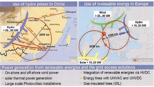
In a recent presentation of the ECPE (European Consortium on Power Electronics) Re-search Roadmap Team on “Power Grid Infrastructure & Renewable Energy Sources”,
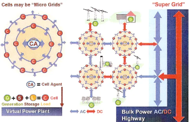
integration of different renewable energies has been indicated as one of the strategic tools to achieve the goal of having the Renewables (Wind and Solar) to contribute up to 30% to the global electricity energy production in 2030. By adding the contribution from hydro power, mainly produced in North-East Europe, the situation depicted in Fig. 1 is predicted, where Solar thermal and PhotoVoltaic (PV) power generation coming from South Mediterranean countries can contribute either with large scale PV installations and solar thermal plants either with distributed small scale PV plants. Integration to the grid of the renewable energies will occur via HVDC, energy lines with UHVAC and UHVDC, and in case of low voltage net-works via distributed intelligent PV converters and advanced PLC. Intelligent Super Grid and Smart Grids interconnected as in Fig. 1 and Fig. 2 within are foreseen as the future energy systems.
In this scenario, while Power Electronics will have to face important challenges such as those of supplying high power Voltage Source Control technology, DC-circuit breakers for meshed HVDC overlay grids, improved DC-grids, and MV DC/DC converters with or without galvanic isolation, power converters for low-power PV generation systems will also cover an increasing important role as they appear the only tool to effectively establish large scale distributed energy, generated by the sun and connected to the grid. In fact, even in the future distributed generation systems exploiting sun energy will continue to be based on a conversion process where power converters, advanced Pulse Width Modulation (PWM) techniques and microcontroller based control systems are associated to achieve high conver-sion efficiency, high power factor, and low current harmonic THD [1][2].
Fig. 2. Future energy system will be formed by intelligent Super Grid and Smart Grids (Source: Siemens AG).
Nowadays, technical improvements and advances in the circuit design of the converters, and integration of the required control and protection functions into the converter control circuit have allowed to introduce into the market advanced PV converter systems that also provide sufficient control and protection functions such as maximum power tracking, inverter current control, and power factor control. Within the range of power till 10 kW several DC/AC converter configurations have been proposed from single stage to double or multi-stage topologies according to the number of cascaded power multi-stages, with or without a low or high frequency power transformer. Single-stage single-phase or three-phase inverters are the traditional solution adopted to interface a large number of PV modules to the grid as the modules are connected in series to create strings with a suitable high value of the output voltage and the strings are connected in parallel through interconnection diodes to obtain the desired power level. The presence of the low-frequency transformer and the poor efficiency of the centralized inverter associated to the poor performance of the Maximum Power Point Tracker (MPPT), have moved to “string conversion” solutions, which basically consist in a double stage power converter for each string of the PV plant. Using an input stage in boost configuration allows one to connect fewer panels in series to create the DC voltage, while increasing the overall efficiency of the power conversion, as the blocking diodes are not requested and the MPPT algorithm is applied to only one string with limited number of panels. String conversion configurations based on several DC/DC converters connected to a
high voltage DC bus and linked to a single DC/AC converter in principle appear as more complex solutions but offer higher efficiency due to single string MPPT control and modular-ity of the PV plant. Finally, for very low-power applications it is recognized that the solution based on AC modules is the best one to solve such issues as input power optimization, plant modularity, and system reliability. With this architecture every single PV panel is directly connected to the grid through MICroinverters (MIC) having the same power of the panel and installed on its back-side.
1.2 Photovoltaic Systems
1.2.1 Problem formulation
The cumulative PV installations reached by the end of 2009 more than 20 GW worldwide experiencing an important growth despite the financial crisis. This shows that the need for renewable energy is a strategic issue due to climatic impact, sustainability and high develop-ment rates in China and India.
The large penetration of PV inverters especially in low voltage networks related to resi-dential/commercial PV plants stability issues are becoming challenging. New, more stringent grid requirements are expected to emerge following the path of wind power with global goal of turning renewable energy power plants in “virtual” power plants. As PV penetration is growing, the impact on grid stability is becoming important. New demands like voltage ride-through, voltage regulation, island operation, are emerging.
Photovoltaic energy generation is becoming increasingly significant in providing sustain-able energy for the ever-increasing needs of the society, and it will play a key role in the world energy scenario.
Mass penetration of PV generation requires not only that the entire PV installation meets performances, but prerequisites new solutions to improve yield, availability, stability and robustness for seamless integration into the electricity network. The efficiency of commercial PV panels is around 15-20%. Therefore, it is very important that the power produced by these panels is not wasted, by using inefficient power electronics systems. The efficiency and quality of both single-phase and three phase PV inverter systems will be improved using new topologies, new controls and ancillary function.
1.2.2 Objectives
The aim of this project is to analyze and develop new topology, exhibit a high efficiency will be proposed, as well as new advanced control algorithms for the PV Power systems. All these functions can be implemented in the current platforms of the PV inverters on the market and turn them in so-called Smart PV Inverters with more market value and increased grid integration potential.
The main societal objective of this project is to facilitate the mass penetration of PV gen-eration therefore contributing to a greener future.
1.3 Main contributions
A short list of contributions is included in the order they appear in the thesis.
• Review and simulation of Module Integrated Converter ( or ACModule) topologies A comprehensive review is presented by modelling several structures: DC/DC and DC/AC topologies, focusing on efficiency and cost. It has been shown that the topology proposed is one of the best compromises in cost, efficiency and high voltage gain. It is also empha-sized that where isolation is needed the best topology is a classic boost interleaved with isolation and regenerative active clamp (presented in the bidirectional DC/DC converter for HEV).
• Review and comparison of a control algorithm for grid synchronization In this thesis, the most popular grid synchronization algorithms were thoroughly reviewed and compared. The comparison was carried out by using simulations tools Matlab/Symulink and Dspace platform. The system was then tested using a real setup. All the algorithms were tested and compared under several distortion conditions (reference)
• PWM techniques comparison The effect of different PWM techniques applied to the PV inverter were analysed while taking the Total Harmonic Distortion factor and efficiency into account. The standard unipolar and bipolar techniques and the mixing frequency technique were incorporated in the analysis. This analysis has shown the potentiality of the mixing frequency techniques compared to the standard techniques.
• New topology In the near future there will be many significant changes in the grid-cod addressing the PV inverter. At the moment PV inverters only feed the active power to the grid using a power factor equal to 1. However, the high penetration of PV inverters in the last few years has caused some problems, because the power injected at the distribution
level has been increased by the DGPS without any update. In fact, when there are many inverters injecting active power at the same time, the voltage at the Point of Common Coupling (PCC) might rise over the limits stated in the standards and trigger the safety of the inverters leading to disconnection or limit the power production below the available power. In order to overcome the mentioned disadvantages, the future standard system will impose to add a new control for the power curtain or for reactive power injection world-wide. This injection will change the structure of the new inverter. Modified Neutral Pont Clamped inverter with new technologies POWER devices has been presented in this the-sis. The structures with these new power devices were compared with the standard under different conditions of load and power factor.
1.4 Outline of the thesis
The continuous increase in power demands makes decentralized renewable energy pro-duction more and more the only way to supply the energy needs next in the future. Decentralized energy production using solar energy could be a solution for balancing the continuously-increasing power demands. This continuously increasing consumption overloads the distribution grids as well as the power stations, therefore having a negative impact on power availability, security and quality.
It is the goal of this thesis to analyze and model and to introduce new strategies for har-vesting high efficiency and high quality in term of energy conversion from photovoltaic systems. The focus of this thesis is to introduce new topology and additional control method.
Chapter 1 of this thesis details the application and motivations of this work while Chapter 2 covers the principles of module integrated converter and its operation. Chapter 3 focuses on a comparison of new topology and the state of the art concerning MIC, Chapter 4 presents hardware setup and experimental results. Chapter 5 present control structure for single phase inverter, focus on PLL. Chapter 6 cover the multilevel issue in renewable energy with conclu-sion and future work covered in Chapter 7 of this thesis.
This thesis goes into detail on the design considerations for every aspect of this system. This includes modeling, simulation, hardware implementation, control algo- rithms and experimental testing
1.5 Scientific production
List of Publications
I. “A New Resonant Active Clamping Technique for Bi-directional Converters in HEVs” N.Abbate, M. Cacciato, A. Consoli V. Crisafulli, G. Vitale; Accepted to be published in ECCE2010, Atlanta Georgia, September 2010
II. “Digital Controlled Bidirectional DC/DC Converter for Electrical and Hybrid Vehi-cles”, N.Abbate, M. Cacciato, A. Consoli V. Crisafulli, G. Vitale; Accepted to be published in EPE-PEMC 2010 Ohrid, Republic of Macedonia, Settembre 2010 III. “A High Voltage Gain DC/DC Converter for Energy Harvesting in Single Module
Photovoltaic Applications”, M. Cacciato, A. Consoli, V. Crisafulli; Accepted to be published in ISIE2010, Bari, July 2010
IV. “Robustness evaluation of phase-locked loop algorithms for single-phase distributed generation systems”, M. Cacciato, A. Consoli, V. Crisafulli, G. Scarcella, G. Scelba; SPEEDAM 2010, Pisa
V. “Latest ST MOSFET and IGBT technologies for the best efficiency in solar invert-ers”, L. Abbatelli, S. Buonomo, M. Cacciato, A.Consoli, V. Crisafulli, R. Scollo; PCIM Europe 2010, Norimberga
VI. “Power Converters dor Photovoltaic Generation Systems in Smart Grid Applica-tions” A. Consoli, M.Cacciato, V. Crisafulli; Revista da associacão brasileira de eletronica de potencia – SOBRAEP vol. 14, no 4, novembro de 2009
VII. “Power Converters dor Photovoltaic Generation Systems in Smart Grid Applica-tions” A. Consoli, M.Cacciato, V. Crisafulli; The 10th Brazilian Power Electronics Conference COBEP 2009
VIII. “Tecnica PWM a Basse Perdite per Sistemi di Generazione Monofase Connessi alla Rete”, A. Consoli , M. Cacciato, V. Crisafulli, G. Frascadore; Convegno Nazionale AEIT 2009 Catania
IX. “Convertitori DC/AC per pannello Fotovoltaico”, A. Consoli , M. Cacciato, V. Crisafulli; Convegno Nazionale AEIT 2009 Catania
X. “ESBT Technology in industrial converters: The best way to cut your losses” S. Buonomo, V. Crisafulli, G. VItale, M. Nania, R. Scollo; PCIM Europe 2008
XI. “ESBT® Power Switch in High Efficiency DC-DC Converter” S. Buonomo, V. Crisaflilli, V. Enea, M. Nania, A. Raciti, C. Ronsisvalle, R. Scollo; IECON 2007. 33rd Annual Conference of the IEEE
XII. “Experimental Investigation of Monolithic Cascode Devices in Inverter Leg Appli-cations”, F Chimento, V. Crisafulli, S. Musumeci, A. Raciti, S. Buonomo, R Scollo; 42nd IAS Annual Meeting
Part I
AC Module
Chapter 2
AC Module Concept
The interest toward the application of MIC converter is increasing in the last years mainly due to the possibility of highly efficient decentralized clean energy generation. The output voltage of a single panel is in the range of 24-36V, generally below 50 V. Conse-quently, low-power applications with high output voltage require a high gain for proper operation. Several solutions were so far proposed in the literature, ranging from the use of high-frequency transformers to capacitive multipliers. In this chapter an evaluation of differ-ent topology is proposed. Finally a prototype of the best topology came from the comparison is presented and tested. This chapter presents the basic concept of photovoltaic generation, continuing with a short overview of grid-connected PV systems and finally presents the MICroinverter or ACModule concept.
2.1 PV cell
In 1839, Becquerel discovered the ability of certain materials to convert sunlight to elec-tricity, when he discovered the photogalvanic effect. The first solar cell has been producted in 1954 by Chapin, Fuller, and Pearson. This cell had a conversion efficiency of 6%. Within 4 years, solar cells were used on the Vanguard I orbiting satellite. The high cost of boosting a payload into space readily justified the use of these cells, even though they were quite expen-sive.
The most popular materials for direct conversion of sunlight to electricity have been crys-talline silicon (Si), amorphous silicon (a-SiH), copper indium diselenide (CIS), cadmium telluride (CdTe), and gallium arsenide (GaAs). All of these semiconductor materials have band-gap energies between 1 and 2 eV.
The band gap of a semiconductor is the energy required to excite an electron from the va-lence band to the conduction band of the semiconductor. Transferring the negative electron to the conduction band creates a positive hole in the valence band. Both charge carriers are then available for electrical conduction.
Sunlight is a very convenient source of energy for creation of these electron–hole pairs (EHPs), since most of the energy in the solar spectrum is at levels higher than the band-gap energies of PV materials. Once the EHP has been produced by an incident photon, the elec-tron and hole must flow in opposite directions. Separation of elecelec-tron and hole can be achieved by using a pn -junction. A pn-junction is composed of material that is rich in elec-trons on one side (the n-side) and rich in holes on the other side (the p-side). The pn-junction produces a built-in electric field, directed from the n-side to the p-side, that separates the photon-generated EHPs. The electrons are forced to the n-side and the holes are forced to the p-side by the junction electric field as long as the EHP is produced within or close to the pn-junction. If the EHP is generated too far from the junction, the electron and hole will recom-bine before they can be separated by the junction electric field.
Fig. 1 Solar Cell
Figure 1 shows photons ( hU) entering a typical PV cell. Some of the photons will create EHPs close to the surface, some will create EHPs near or within the junction region, and some will penetrate beyond the junction. Generally, the highest-energy photons produce EHPs close to the surface, whereas the lowest-energy photons penetrate the deepest. This process of liberating an EHP results in the conversion of part of the energy of the incident photon to electricity. Any leftover energy is converted to heat. If the EHP is produced near or within the pn-junction, the electron is swept into the n-region and the hole is swept into the p-region. The electrons (V) then diffuse toward the top of the cell and the holes (+) diffuse toward the bottom of the cell. As the electrons reach the top surface, where there is a contact to an external circuit, they continue to flow into the external circuit. As the holes reach the bottom surface, where there is another contact to the external circuit, they recombine with electrons flowing in from the external circuit. For each electron that leaves the top, another enters the
0 5 10 15 20 25 30 35 40 45 0 20 40 60 80 100 120 P(V) characteristic Voltage [V] P ow er [W ] 0 5 10 15 20 25 30 35 40 45 0 0.5 1 1.5 2 2.5 3 3.5 4 I(V) characteristic Voltage [V] C ur re nt [A ] (a) (b) 0 100 200 300 400 500 600 0 500 1000 1500 P(V) characteristic Voltage [V] P ow er [W ] 0 100 200 300 400 500 600 0 0.5 1 1.5 2 2.5 3 3.5 4 I(V) characteristic Voltage [V] C ur re nt [A ] (c) (d) 0 100 200 300 400 500 600 0 200 400 600 800 1000 1200 1400 P(V) characteristic Voltage [V] P ow er [W ] 0 100 200 300 400 500 600 0 0.5 1 1.5 2 2.5 3 3.5 4 I(V) characteristic Voltage [V] C ur re nt [A ] (e) (f) 0 100 200 300 400 500 600 0 500 1000 1500 P(V) characteristic Voltage [V] P ow er [W ] 0 100 200 300 400 500 600 0 0.5 1 1.5 2 2.5 3 3.5 4 I(V) characteristic Voltage [V] C ur re nt [A ] (g) (h) 0 100 200 300 400 500 600 0 500 1000 1500 P(V) characteristic Voltage [V] P ow er [W ] 0 100 200 300 400 500 600 0 0.5 1 1.5 2 2.5 3 3.5 4 I(V) characteristic Voltage [V] C ur re nt [A ] (i) (l) 0 100 200 300 400 500 600 0 500 1000 1500 P(V) characteristic Voltage [V] P ow er [W ] 0 100 200 300 400 500 600 0 0.5 1 1.5 2 2.5 3 3.5 4 I(V) characteristic Voltage [V] C ur re nt [A ] (m) (n)
Fig. 2 (a) V-I single PV-panel 120 W; (b) P-V single PV-panel 120 W; (c) V-I 12 PV-panels 100% irradiance; (d) P-V
12 PV-panels 100% irradiance; (e) V-I 12 PV-panels 100% irradiance with 50% effect shadow level; (f) 12 PV-panels 100% irradiance with 50% effect shadow level; (g) V-I 12 PV-panels 100% irradiance with 10% effect shadow level;
(h) P-V 12 PV-panels 100% irradiance with 10% effect shadow level; (i) V-I 12 PV-panels 100% irradiance with 10% effect shadow area; (l) P-V 12 PV-panels 100% irradiance with 10% effect shadow area; (m), V-I 12 PV-panels 100% irradiance with 50% effect shadow area; (n)P-V 12 PV-panels 100% irradiance with 50% effect shadow area;
bottom. This completes the circuit, with electron flow in the external circuit and the flow of both electrons and holes within the PV cell. The challenge in the design of the PV cell is to absorb all incident photons close enough to the pn-junction so all electrons and holes gener-ated will be collected. A further challenge in cell design is to minimize conversion of sunlight to heat and maximize conversion to electricity. Because of the pn-junction, a voltage appears between the bottom and the top of the cell. This voltage is what forces the current through the external circuit. Depending upon the cell material, the voltage developed by the cell may range from very small up to about 1 V. Thus, to produce higher voltages, the cells must be connected in series. When cells are connected together, normally they are incorporated into PV modules, which often combine as many as 40 cells in series to produce voltages in the range of 20 V and currents of several amperes. When voltages and currents beyond the capability of an individual module are desired, the modules can be connected into arrays that will produce higher voltages and higher currents. Although most cells produce only a few watts, and most modules produce 10 to 300 W, most arrays produce a few thousand watts. A few very large systems have been deployed that produce power in the megawatt range.
An important feature of all modern PV cells is that, over their lifetimes, they can produce up to ten times as much energy as was used in their fabrication and deployment.
The ideal solar cell operates as a diode when in the dark, and operates almost as an ideal current source when operated under short-circuit conditions. The short-circuit current of the cell is close to directly proportional to the intensity of the sunlight incident on the cell. The current source nature of the cell means that if cells are connected in series to increase their overall voltage, the cells must be closely matched so each cell produces identical current
Fig. 3 (a) multistring system; (b) single string system
+
under identical illumination conditions. If this is not the case, the voltage of the series combination will not be optimized. The I–V relationship for the ideal PV cell is given by Eq.1
= 0 1 v q t k L I e I I Eq. 1
where IL is the photon-generated current component, I0 is the cell reverse saturation
cur-rent, and k*T/q=25.7 mV at a temperature of 25°C. More specifically, the photocurrent is related to sunlight intensity by the relationship: Where G is the sunlight intensity in W/m 2 and Go= 1000 W/m 2.
Figure 2 shows the different behaviour of the PV module under normal condition and shadow condition. Fig. 2 (a) and (b) (a) show the I–V and P-V characteristics as a function of incident sunlight for a single PV panel. Fig. 2 (c) and (d) show the I–V and P-V characteris-tics as a function of incident sunlight for an array of 12 PV-panels (as shown in Fig. 3). The other plots in Fig. 2(x) show the same characteristics under different condition of shadow area and shadow level of the PV array. It is evident the degradation of the P-V and I-V characteris-tic under abnormal condition. Note that as the temperature rises, the open circuit voltage of the PV-cell, VOC, decreases. For Si cells, the rate of decrease is 2.3 mV/°C for each cell. Thus,
a 36-cell module (as shown in Fig. 4) operating 25°C above ambient temperature, will lose 36 ×2.3×25= 2070 mV = 2.07 V. This is nearly a 10% loss in output voltage, which, when coupled with approximately temperature-independent current, results in a 10% power loss. The departure of the I–V characteristic of a real cell from that of a perfect cell is measured by the fill factor (FF) of the cell. The assumption is that a perfect cell would have a rectangular characteristic, with constant current up to the maximum cell voltage, and then constant voltage. The constant current would be the short-circuit current and the constant voltage would be the open-circuit voltage. Since the current produced by a cell depends upon the total power incident of the cell, if a cell is shaded even partially, it will not produce the same current as unshaded cells. At a certain point of shading, the polarity of the cell voltage re-verses to enable the cell to carry the current generated by the unshaded cells in the module. When this happens, the cell dissipates power, and can overheat to the point of cell degrada-tion.
To protect the module against cell degradation, bypass diodes are normally incorporated into the module design to shunt current away from shaded cells, as shown in Fig. 3.
If the voltage of a module drops below the voltage of other modules connected in paral-lel, it is possible for the current produced by the higher-voltage modules to flow in the reverse
Fig. 4 PV-Cell and V-I characteristic
direction of the lower voltage module. To prevent reverse flow of current through a mod-ule, a blocking diode is sometimes used in series with the modmod-ule, as shown in Fig. 3.
2.2 ACmodule Concept
Solar power production is affected by various factors such as module mismatch, obstruc-tion shading, inter-row shading, and obstacles such as dust or debris. In addiobstruc-tion, non-uniform changes in temperature, irradiance, and shading create complex current-voltage curves, further affecting energy harvest. This is due to the fact that in traditional systems the perform-ance of the entire system is dictated by the performperform-ance of the weakest module.
Inverter R&D has focused on two areas. The first is incremental changes in the existing string/central inverter, and most of these changes are geared toward higher efficiency and larger capacity. These changes have led to bigger, more centralized inverters, for example, SMA’s new 500kW 500U PV inverter.
The second recent inverter development is a move toward decentralized architectures, in-cluding partial solutions such as DC-to-DC optimizers, consisting of add-on electronics designed to augment a central inverter, and complete inverter solutions such as microinverters [3].
Recently, the development of a new energy conversion solution in low power Photo-Voltaic (PV) generation systems has started.It consists in the integration of a small converter inside the junction box of PV panels used for solar energy harvesting. Such a converter, called AC Module (ACM), shows AC output characteristics with grid-connection capability without external DC connector. ACMs should achieve similar costs of the produced kWh as those
obtained with standard systems. Therefore, in developing a new ACM system the main issues regard the converter efficiency and cost.
Although the characteristics of the ACM may change according to panel specifications, its structure is composed by the cascade connection of two stages, a DC/DC and a DC/AC. The DC/DC stage is used to boost the output voltage of the PV module up to a value suitable for connecting the module to the grid with standard single-phase inverter. The DC/DC con-verter is also responsible for implementing the Maximum Power Point Tracking (MPPT). Therefore, high efficiency and elevated voltage gain are the most important performance required in this application to the DC/DC converter. In particular, high voltage gain can be obtained through charge-pump systems or high-frequency transformers that remain the only solution in case a galvanic isolation is required.
At the moment one of the main issues in “Solar Conversion” is to obtain the maximum power available from the field in all weather conditions. In order to get the Maximum Power a lot of specific control algorithms, such as MPPT (Maximum Power Point Tracking), have been done. Conventional system modules linked together in series may perform differently, simply because of dirt or accidental shadowing. Under these conditions, the MPPT is unable to function properly and adapts all modules to the worst performance and penalizes such all. In order to solve this problem a new topology has been used, which is adopted by many manufacturers: one inverter circuit is combined with multiple independent MPPT's that divide the plant. However, an inverter of several kilowatts, even in case of multi-string, requires a high voltage input. In this case, the shading problem continues to persist. Figure 1 shows in the left side the model of a string converter, while in the right side different configuration for string converter.
When the PV series string is operating under non-uniform conditions of radiation, as it is often the case in PV array, a problem arises. All the cells in the system share the same current, and when a cell or group of cells is shaded one of two scenarios may occur:
• The group of shaded cells will try to drive the unshaded ones into operating at a lower current level. In this case the system output power is limited by the current produced by the cell or panel generating the lowest output current.
• The unshaded cells will try to drive the shaded ones into operating at a higher current level. The only way a PV cell can operate at a higher current than its short circuit cur-rent, which is directly proportional to irradiance, is by moving into the negative voltage region of the cell’s I-V curve where it becomes reverse biased as shown in Fig. 1. At this point the panel’s backplane diode(s) becomes forward biased and it conducts the string current. The down side is that now the group of shaded cells is
en-tirely bypassed, contributing zero power to the system, and the string voltage is also affected.
It is apparent that due to widely varying voltage levels of the series string, another dc-dc converter is needed to regulate the dc input voltage to the inverter. The Maximum Power Point Tracker within the inverter decides which of the two situations described above takes place. This central converter must be able to operate at high voltages and currents and with-stand large voltage swings. Such a component may increase the complexity of the controls of the system, but more importantly, it will add significant cost and losses to the PV installation.
In order to address and try to mitigate the series string problem, a concept called the Module Integrated Converter (MIC) was developed. It solves the series string problem by adding dc-dc converters at the output of each panel. The overall tolerance of the system against irradiance mismatches is improved because now each panel is not affected by the operating conditions of its neighbours.
The concept of the AC photovoltaic module or Module Integrated Converter, a photo-voltaic module with an integrated DC/AC, has been proposed several years ago at Caltech’s Jet Propulsion Laboratory, but is only now reaching commercial realization.
The AC Module concept has many advantages over central inverter systems, the main ones being a low minimum system size and the ability to site individual modules without concern for shading and orientation.
A module integrated converter approach whether DC/DC or DC/AC has many advan-tages:
• AC Module systems improve system reliability because of distributed hardware (re-dundancy), testability (via communications links) and simplicity (no high voltage DC components or wiring)
• Better Utilization (MPPT) per module basis: Each module can independently control and so optimise the power flow to or from its source. In a solar power application, each module can independently perform maximum power point tracking (MPPT) for its PV-panel. This allows panels to be given different orientations opening up new possibilities in architectural applications. Greater tolerance of localised shading is now also possible. These reasons taken together are the most important advantage of per-panel distributed modules.
• Mixing of different sources becomes possible: Independent and intelligent power flow control can decouple each source from the others in the string. Batteries could be re-placed individually as required since old and new batteries can now be mixed.
Existing PV module strings could be extended with new higher output panels without compromising overall string reliability or performance.
• Better protection of module power sources: Intelligent protection can be applied on a per source basis. A single shaded PV module can deliver its power rather than being bypassed by a diode for its own protection.
• Redundancy of both power converters and modules: An intelligent module can bypass a failed source or indeed a failed converter if appropriately designed, allowing the complete installation to continue operation at slightly reduced capacity.
• Greater safety during installation and maintenance: Depending on design, each module may be able to isolate its connected power source, so the wiring of series or parallel connections of modules can be performed safely. The module, power source connec-tion is a safe low voltage connecconnec-tion.
• System design and installation costs are reduced via product standardization
• The minimum array increment of one AC module and the elimination of balance-of-system equipment allows for maximum flexibility in initial sizing and simple future array expansion
• AC arrays are exposed to damage from nearby lightning strikes.
Inverter technology has always had a significant impact on energy harvest. The serial na-ture of module installation results in the “Christmas light effect,” i.e., any impact (dust, debris, shade) on module performance will also affect the other modules in the string. Distrib-uted inverter architectures mitigate this effect as each module becomes an independent power producer. Per-module MPPT enables increased energy harvest.
There are of course some disadvantages. The main one is that for systems over about 50 kW total, a central inverter can be made very cheaply - it is likely that large systems “behind the utility fence” will not be AC module devices.
Possible disadvantages of AC-modules are the following:
• Increased zero-load dissipation compared to conventional PV-systems.
• Increased thermal stress on the inverter, because the inverter is mounted on the back of the module.
• New residential scale PhotoVoltaic (PV) arrays are commonly connected to the grid by a single DC-AC inverter connected to a series string of PV modules, or many small DC-AC inverters which connect one or two modules directly to the AC grid.
• ACMs must operate in a very harsh thermal environment which affects their compo-nent lifetime;
• ACMs interaction can be an issue in large PV plants;
• high efficiency is difficult to be obtained in small power converters;
• system costs.
2.3 Series vs. parallel string of module-integrated converters.
The present grid connected module integrated converters that convert directly to 240Vac can lay claim to these advantages. However, this approach of direct grid connection has the disadvantage of a large difference in voltage from input (low) to output (high). This requires a transformer based converter, which requires more mass and volume, is more expensive, and is less efficient than a simple DC-DC converter [4][5][6].
A series rather than parallel connection of converters allows the input-output voltage ratio to be close to unity, which leads to the highest switch utilisation, and removes the need for a transformer. Efficiencies of close to 100% are possible, and converters can be small, light and low cost.
A series connection utilises low voltage MOSFETs, Schottky diodes, inductors and ca-pacitors that have been developed for low voltage DC-DC converters. A parallel connected converter requires high voltage fast recovery diodes and MOSFETs, which are at a perform-ance vs. cost disadvantage.
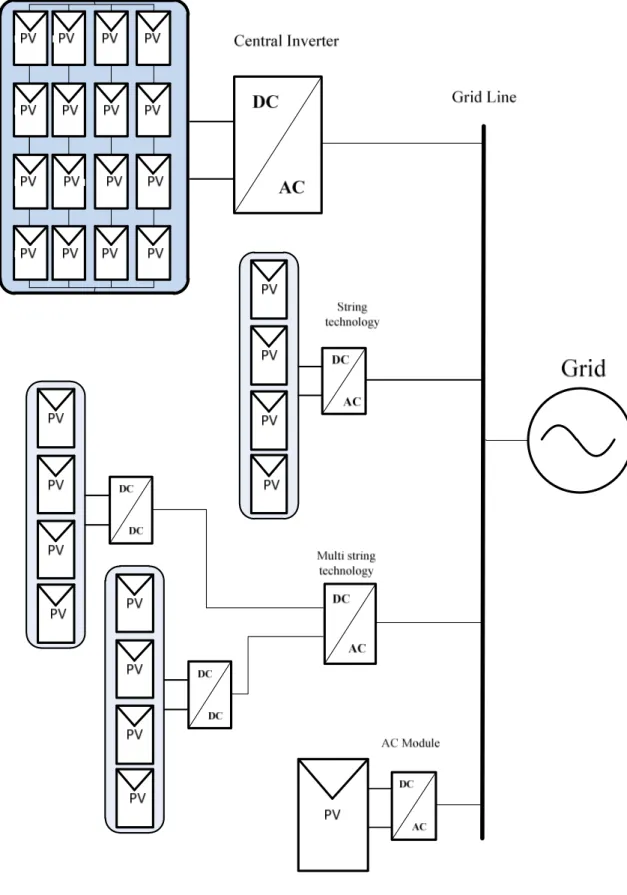
2.3.1 Central Inverter
In the Photovoltaic scenario the most common system layout is the centralized inverter, or plant-oriented, topology, which consists of series connected PV modules (also called PV strings) all connected in parallel in order to fit voltage and power constraints, as shown in Fig. 6,has led this structure to be widely used in large grid-connected installations. . The PV modules were divided into series connections (called a string), each generating a sufficiently high voltage to avoid further amplification. These series connections were then connected in parallel, through string diodes, in order to reach high power levels. These series connections were then connected in parallel, through string diodes, in order to reach high power levels. The benefits of this topology are the low specific converter cost and simple maintenance.. This centralized inverter includes some severe limitations, such as high-voltage dc cables between the PV modules and the inverter, power losses due to a centralized MPPT, mismatch losses between the PV modules, losses in the string diodes, and a non flexible design where the benefits of mass production could not be reached. The grid-connected stage was usually line commutated by means of thyristors, involving many current harmonics and poor power quality. The large amount of harmonics was the occasion of new inverter topologies and system layouts, in order to cope with the emerging standards which also covered power quality.
Centralized PV inverters perform two major functions: power conversion from DC to AC; and Maximum Power Point Tracking (MPPT):
• Power Conversion
Traditional solar energy central and string inverters convert current by ‘chopping’ the 200 to 480 volt DC voltage from the source solar strings, typically using local controls and a power conversion bridge. By filtering and tuning the frequency of the supply, the inverter ensures the current is in phase with the grid to ensure the current is grid-compliant and can be used for standard residential or commercial loads or sold back to the utility.
• Maximum Power Point Tracking (MPPT)
The goal of the MPPT algorithm is to extract the greatest power available from the solar array. The better the MPPT algorithm, the greater the power output. With a central inverter, the MPPT is performed on the solar array as an aggregate. However, changes in temperature,
irradiance, and shading create complex current-voltage curves, thereby making it difficult or impossible for the MPPT algorithm to find a power point that is optimal for all modules. This results in a compromise in operating conditions and results in less than optimal energy harvest.
In addition, varying roof orientations, and module mismatch (often resulting from typical manufacturing tolerances) can also have an impact on energy harvest. Other challenges associated with centralized inverters include the space required to locate the device, as well as heat dissipation requirements. Large central inverters are typically actively cooled. These cooling fans can make a tremendous amount of noise , so location of the inverter relative to offices and occupied areas must be considered.
2.3.2 String Inverter
Recently, in photovoltaic installation, the string inverter have been preferred compare the central inverter strategy. The string inverter, shown in Fig. 6, is a reduced version of the centralized inverter, where a single string of PV modules is connected to the inverter. String inverters prevents mismatch losses between strings and lets each string operate at its maxi-mum power point. Furthermore, string diodes are removed which reduces energy losses. Yet, the extra inverters not only add power conversion losses but also elevate the cost of the PV system. That is one of the reasons why large plants usually favor centralized configurations.
In terms of continuity of service, it is very unlikely that all string inverters are down si-multaneously, which ensures at least a minimal photovoltaic production on the grid. String inverters are also future proof, in the sense that the capacity of a module oriented installation can be upgraded easily, if the grid connection allows additional capacity flow. An additional innovation to this topology is the team concept which aims to improve power conversion efficiency during low solar irradiance. By using dc switches which cross-connect strings together, as shown in Fig. 6, the strings may be combined (as in the centralized topology) in order to accept a larger solar irradiance PV production range and enhance conversion effi-ciency by using only one inverter
The input voltage may be high enough to avoid voltage amplification. This requires roughly 16 PV modules in series for European systems. The total open-circuit voltage for 16 PV modules may reach as much as 720 V, which calls for a 1000-V MOSFET/IGBT in order to allow for a 75% voltage de-rating of the semiconductors. The normal operation voltage is, however, as low as 450-510 V. The possibility of using fewer PV modules in series also exists, if a dc–dc converter or line-frequency transformer is used for voltage amplification. There are no losses associated with string diodes and separate MPPTs can be applied to each string. This increases the overall efficiency compared to the centralized inverter, and reduces the price, due to mass production.
2.3.3 Multi String Inverter
The multi-string inverter depicted in Fig. 6, is the further development of the string inverter combines the two previous topologies by introducing a dc-dc converter with MPPT control strategies for each string of the PV array. Several strings are interfaced with their own dc–dc converter to a common dc–ac inverter. This is beneficial, compared with the centralized system, since every string can be controlled individually. The dc-dc string converters are also used to elevate PV string voltage to a high voltage dc bus while using a MPPT strategy. The introduction of a dc bus reduces inverter functionalities, for example the MPPT is transferred to the DC/DC converters and also eases heterogeneous PV module integration. Indeed, modules used from one string to another, may differ in age, size, technology, or even nominal power values Thus, the operator may start his/her own PV power plant with a few modules. Further enlargements are easily achieved since a new string with dc–dc converter can be plugged into the existing plat- form. A flexible design with high efficiency is hereby achieved. Finally, the ac cell inverter system is the case where one large PV cell is connected to a dc–ac inverter. The main challenge for the designers is to develop an inverter that can amplify the very low voltage, up to an appropriate level for the grid, and at the same time reach a high efficiency. For the same reason, entirely new converter concepts are required.
2.3.4 MIC or AC Module
The ac module depicted in Fig. 3 is the integration of the inverter and PV module into one electrical device. It removes the mismatch losses between PV modules since there is only one PV module, as well as supports optimal adjustment between the PV module and the inverter and, hence, the individual MPPT. It includes the possibility of an easy enlarging of the system, due to the modular structure. The opportunity to become a “plug- and-play” device, which can be used by persons without any knowledge of electrical installations, is also an inherent feature. On the other hand, the necessary high voltage-amplification may reduce the overall efficiency and increase the price per watt, because of more complex circuit topologies. On the other hand, the ac module is intended to be mass produced, which leads to low manu-facturing cost and low retail prices.
The present solutions use self-commutated dc–ac inverters, by means of IGBTs or MOS-FETs, involving high power quality in compliance with the standards.
2.4 What is String converter?
MIC is a new concept, concerning renewable energy. Photovoltaic cells produce direct current (dc) power. The utility wiring and appliances within the home use alternating current (ac) power with voltages in the range of 110 Vrms (USA) and 220 Vrms (Europe). Therefore all grid connected PV installations require an inverter to convert power from dc to ac. The input dc voltage to the inverter must be large in order to most efficiently convert to the ac-line voltage. The standard solution for achieving this is by connecting several PV panel in series in order to build up the system’s output voltage.
In a dc-dc converter, power is converted from dc to ac by periodic switching of the tran-sistor. The ac power signal, also referred to as indirect power, is then rectified again through the diode and converted back to dc. The key to obtaining high efficiency in this application is the minimization of indirect power at the nominal operating point. This implies generating the least amount of ac power possible by minimizing switching and processing of the input dc signal. This is achieved by use of a converter having a buck-boost characteristic, designed to have a voltage conversion ratio of unity at the nominal operating point. The circuit can operate in a mode called “pass-through” which achieves maximum efficiency by directly connecting input and output ports of the converter. Neighbouring operating points in the buck or boost mode also exhibit (MPPT) DC/DC converter (MPPT) very high efficiency, and hence the insertion loss for this approach is very low. This architecture allows for maximum flexibility and improved tolerance in a system under mismatched conditions.
The MPPT block of this system operates independently from changes in the string cur-rent, which allows the converters to exhibit output characteristics of a constant power source. This means that the string current and voltage are adjustable, and it is possible to regulate the string voltage by tuning the string current. With a fixed string voltage the string becomes modular and it is possible to easily add more strings in parallel or connect the system to a battery bank. Additionally, the central dc-dc converter becomes redundant and unnecessary, greatly improving the total power output of the PV installation at a minimum added cost.
In 2001 Shimizu introduced a Generation Control Circuit capable of “shuffling” power between adjacent PV modules. This concept was further improved two years later by Walker, who proposed non-isolated, inverting, bidirectional dc-dc converters for the same purpose. This proposal is intended for series connected PV strings that are evenly lit, and therefore the efficiency of the converters is optimized for their quiescent state. Each MIC processes only the power difference between adjacent modules, allowing them to operate at different currents
as long as the shuffling converters support this current difference. This way a power stage with smaller rating and higher efficiency can be implemented.
However, the author notes that in the worst case scenario where two adjacent modules are shaded, the converters connected to these panels must operate in deep buck mode in order to supply the full string current of the array. Therefore the MIC must be rated after all, for the same current, voltage and power as the panel they support. Another converter is necessary at the string level in order to interface the top and bottom modules. A bidirectional Flyback is suggested for the central dc-dc converter. The efficiency of the flyback converter, generally notorious for being low, is not included in the author’s simulation of the system.
It is also important to note that these converters implement a passive form of MPPT, by simply operating at a fixed panel voltage, close to the maximum power point voltage. The main assumption being that changes in irradiance and temperature will be low enough that the voltage at the maximum power point will only vary slightly. Active maximum power point tracking is performed by the array’s dc-ac inverter.
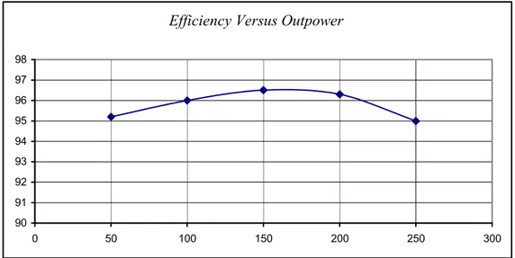
Four different converter topologies for PV module integration have been investigated by Walker and Sernia in 2002. Efficiency vs. input power for each of these was predicted via simulation for a 60 W module using synchronous rectifiers. The authors concluded that the boost converter is not capable of always delivering the full amount of output power from a series connected string under shading conditions. The buck converter can deliver any amount of power, but the string will require many more panels. If the buck or boost converters reach a minimum or maximum duty cycle boundary, the string output voltage will be limited. The dc-dc converter at the string level is still necessary to ensure proper regulation of the dc-dc input to the inverter. The authors concluded that the buck-boost and Chuk converters were too expen-sive and inefficient to be deemed practical.
2.5 Summary
The PV cell was introduced in this chapter. The mode of operation under normal and ab-normal condition was also presented. The partial shadow is also treated in many papers. The case of partial shadow is included in the chapter in order to show the problems associated with it. Thus, even a small amount of partial shadow may result in severe power losses, and the risk of delamination, and a very irregularly voltage-power characteristic. The irregularly characteristic is a problem for most Maximum Power Point Trackers (MPPT). This is re-garded as a problem, which must be dealt with.
Finally, the MICroinverter concept has been presented with a short review of its history and types of technologies.
Chapter 3
MIC for Photovoltaic modules
The interest toward the application of MIC converter is increasing in the last years mainly due to the possibility of highly efficient decentralized clean energy generation. The output voltage of a single panel is in the range of 24-36V, generally below 50 V. Consequently, low-power applications with high output voltage require a high gain for proper operation. Several solutions were so far proposed in the literature, ranging from the use of high-frequency transformers to capacitive multipliers. In this chapter an evaluation of different topology is proposed. Finally a prototype of the best topology came from the comparison is presented and tested..
3.1 Strengths of ACModule
Although the design techniques of converters for PV panels may change according to the panel specifications, efficiency and voltage gain are the two most important performances required to such architectures. In particular, a high voltage gain of the DC/DC converter is requested and this can be obtained through charge-pump systems or high-frequency trans-formers, which remain the best choice in case galvanic isolation is required.
Although the classic boost converter is theoretically capable of reaching a high voltage gain, in practice, the gain declines as the duty cycle approaches unity due to parasitic compo-nents. In addition, the control stability at operation with very high duty-cycle values is severely affected.
One alternative would be associating in cascade either conventional boost converters or interleaved variants or employing a modified cascaded boost in order to achieve the required gain. A major disadvantage here is the poor efficiency level due to losses in the two succes-sive power processing stages.
To surpass such limitations, several topologies proposed in the literature can achieve high voltage gain without requiring high values of duty cycles or multiple cascaded stages. A common important feature is also the reduced voltage stress across the active semiconductors.
Such features can be achieved by one of the following techniques, as will be discussed in the succeeding sections: isolated magnetic means, non isolated magnetic means, and finally, capacitive means.
In addition, higher levels of efficiency are, in general, not attainable due to the associa-tion of several power processing stages. An alternative to the previous circuits is the use of the high frequency transformer as an energy storage inductor, like in variants of the isolated dc– dc forward or push–pull converter. Such solutions are nevertheless normally limited to lower power levels and also attain reduced efficiency, with the rise of problems like high voltage stress, large switching losses, and electromagnetic interference problems, mainly due to the negative effect of the leakage inductance and winding capacitance of the transformer. In order to bypass such drawbacks and reach a higher level of efficiency, the circuit proposed in [20] modifies the basic current-fed push–pull converter to employ a current doubler stage that reduces conduction losses in the input stage and a zero-current-switching voltage multiplier in the output with no losses due to reverse recovery.
High gain is also achieved here through the turns-ratio relation, although, now, non-isolated structures like coupled inductors or magnetically coupled non-non-isolated converters are considered. One first example of such approach would be a boost converter where two magnetically coupled windings are placed before and after the switch so that not only is the gain increased but also the voltage stress across the switch is reduced. In order to deal with the problem related to the leakage inductance, several clamping circuits as proposed in in literature. When compared with the galvanic isolated topology circuits, the circuits in this section are capable of achieving a higher level of efficiency as only a single stage is present. In addition, reduction of the voltage stress across the semiconductors is possible in most circuits, which allows further reduction of the losses and costs.
3.2 Topologies under comparison
There are several design strategies for converters panel. The most serious problem is re-lated to the high voltage gain that is required of the stage DC / DC converter. For good performance, this value of gain can be obtained by using charge-pump systems or through the use of high frequency transformers. In countries that require galvanic isolation is better to use the second strategy, if the use of a high frequency transformer is considered sufficient.
boost insulated classic. This converter shows a very high gain achieved through the use of a transformer with a secondary center-tapped. The control strategy of the devices is a classic PWM interleaved between the two channels to reduce input ripple current. In fact, the transis-tors Q1 and Q2 are made to switch at the same frequency and with the same duty cycle but 180 ° out of phase signals to each other. High gain is achieved here through the turn-ratio of a high frequency transformer that provides galvanic isolation between the source and the grid and also normally allows the use of low voltage-rated active switches in the input side. The high-frequency waveform in the input of the transformer can be generated by a voltage-fed or current-fed full bridge inverter, whereas the last one attains reduced semiconductor conduc-tion losses since both legs are connected in parallel during the short-circuit interval. The output is then rectified by a conventional diode bridge. Two inherent disadvantages of such circuits are the high amount of switching losses, as higher frequencies are normally employed to reduce the size of the transformer, and the higher conduction losses due to the sum of inverter and rectifying stages. In order to deal with the first disadvantage, the use of a soft-switching technique can be employed, although a common drawback is the increased com-plexity in the operation and construction. The switch control strategy is a standard interleaved Pulse Width Modulation (PWM) between the two channels, able to reduce the ripple of the input current, as the two transistors have the same switching frequency and duty-cycle and a phase shift of 180°.
A possible solution for the second disadvantage is to substitute the diode bridge with a high-frequency active voltage doubler leg that provides reduced conduction losses with additional gain. As a conclusion regarding the circuits discussed so far in this section, the use of a high-frequency galvanic isolation is more appropriate when very high gains are required or at medium power levels.
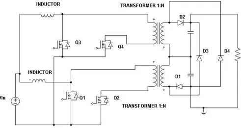
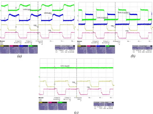
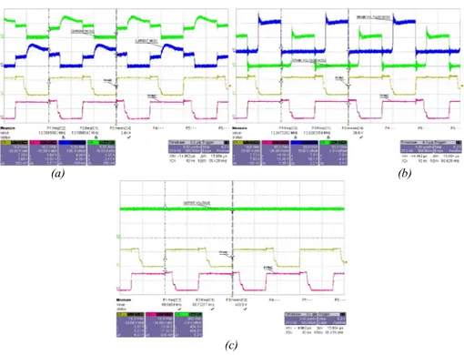
Fig. 8 shows a dual interleaved isolated boost converter. The high gain is obtained
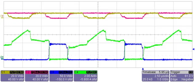
through the two center-tapped transformers that load the output capability. The control strategy is slightly different from the previously stated but easy to implement. There are two interleaved phases, each with two transistors. The devices at each stage Q1-Q2 and Q3-Q4 are controlled by signals out of phase with each other by 180 ° and slightly overlapping, as shown in Fig. 9.
The dual boost-interleaved converter uses two high-frequency transformers to charge the output capacities and again ensure the high voltage gain. In this case two interleaved phases are introduced with two transistors each, which are driven according to the shown strategy