Università Politecnica delle Marche
Scuola di Dottorato di Ricerca in Scienze dell’Ingegneria Corso di Dottorato in Ingegneria Industriale
---
Experimental Dynamic Characterization
of Tire/Tire Components
Ph.D. Dissertation of:
Stefano Galeazzi
Supervisor:Prof. Enrico Primo Tomasini
Assistant Supervisor:
Prof. Paolo Chiariotti Prof. Milena Martarelli
Ph.D. Course coordinator:
Prof. F. Mandorli
Università Politecnica delle Marche
Scuola di Dottorato di Ricerca in Scienze dell’Ingegneria Corso di Dottorato in Ingegneria Industriale
---
Caratterizzazione dinamica sperimentale
dello pneumatico e di suoi componenti
Ph.D. Dissertation of:
Stefano Galeazzi
Supervisor:Prof. Enrico Primo Tomasini
Assistant Supervisor:
Prof. Paolo Chiariotti Prof. Milena Martarelli
Ph.D. Course coordinator:
Prof. F. Mandorli
Università Politecnica delle Marche
Dipartimento di Meccanica
Abstract
The reduction of the noise generated by rolling tire is becoming one of the most important and difficult challenges for tire manufactures. The increasing interest in tire noise performance is related both to the requirements coming from the car industry and to new regulations that impose a significant reduction of the noise emitted by tires in order to reduce the acoustic pollution of our cities. Rolling tire is the second noise source of a car; the first one is the engine. During last years, a lot of work has been done in order to make the interior of the cars as comfortable as possible and the current insulation can significantly reduce the noise coming from the engine, so, in order to increase the comfort level, the car manufacturers ask for silent tires. Rolling tire generates also noise propagating in the surroundings causing unpleasant noise for the people outside the car. From this short introduction it is clear how complex the phenomenon is and that there is a double problem, because both the in-vehicle (noise perceived by car passengers) and the exterior noise (noise propagating in the environment) must be considered, but, even if the noise source is the same, they are different phenomena and require dedicated countermeasures.
To obtain the noise reduction, it is necessary to consider the effect on noise emission of every components and materials used in tire construction. To do this it is necessary to better understand the noise generation mechanisms, in fact even if a lot of researchers have studied this phenomenon for decades, it is still not completely clear how noise is generated. For sure, one of the most important causes are the vibrations of the rolling tire.
This project deals with the study of tire vibrations using an innovative set-up based on the Digital Image Correlation technique. This technique has several advantages if compared with the current techniques among which the possibility to perform significative measurement of tire crown. This is one of the innovations introduced in this work, since this measurement can provide new information not available in the past years. In fact, all the other vibration measurement set-ups cannot perform this kind of measurement because of the presence of tire pattern generating an inhomogeneous surface. The new dynamic characterization of tire crown and its comparison with sidewall provide new information about rolling tire vibrations that suggest some countermeasures for the development of a noise-oriented tire structure. Two case studies are described to demonstrate the potentialities of the new set-up and demonstrating how an important noise reduction can be achieved.
In the second part of this PhD Project, the same set-up has been used to characterize some tire components with a dynamic noise-oriented characterization. It represents a completely new approach to the problem since the current characterization is performed in quasi-static condition or dynamically on small samples of rubber only: with these tests it is possible to completely characterize the rubber used for tire compound and the cords used as reinforcing fabric, but there are no physical or mechanical properties useful for the noise emission prediction. This lack of information is related to approach used: in the past years, tire silence was a secondary requirement. Nowadays, the reduction imposed is so strong, that tire developers are forced to consider it from the first stages of the development and the
absence of such a characterization has emerged. The proposed approach considers samples produced in the same way they can be found on the final tire: they are slabs made of a calendered rubber layer with embedded cords. Currently, rubber and reinforcing materials are separately characterized and it is not possible to predict the effect of a material on noise. The only way to know it is producing a tire and acoustically test it. In this way a lot of time and money are spent. The new proposed approach tries to evaluate the mobility of the samples and uses it as criterion to select the materials which are supposed to have a positive effect in terms on noise reduction. For sure, the final response comes from the test of the prototype, but in this way the selection of the proper materials is faster and, at the same time, the number of tests on tire and the prototypes produced is significantly reduced. In order to obtain good and useful results it important to define the correct structure of the samples, in fact even if the idea is to characterize the cap ply or body ply layers, the sample must contain also the belt package for global stiffness and mass reasons: if the belt is not used, the slab produced is very lightweight and the variation of the cord cause significant variations in terms of mass with a shift in terms of resonance frequencies that it is not related to mechanical properties of the cord materials or sample thickness, but it is related to the mass variation. When the belts are applied, the samples have almost the same mass and stiffness and the effect of the different cap ply layers is a variation of the mobility. The performed measurements suggest that the new approach produce interesting results correlating with vibration measurement on rolling tires.
In conclusion it can be said that an innovative measurement set-up for the characterization of rolling tire has been developed and validated and an innovative approach for noise reduction based on the characterization of tire components has been proposed.
Riassunto
La riduzione del rumore generato dagli pneumatici in rotolamento rappresenta una delle sfide principali e più difficili per le case produttrici e per gli ingegneri di sviluppo. Negli ultimi anni, infatti, c’è stato un sempre crescente interesse verso questo argomento a causa di richieste provenienti sia dal mondo automobilistico che dalle nuove normative in termini di inquinamento acustico, che impongono un forte abbattimento del rumore generato dagli pneumatici. Il rotolamento degli pneumatici sull’asfalto genera un rumore che viene percepito in maniera fortemente sgradevole all’interno del veicolo ed è piuttosto fastidioso. La richiesta di pneumatici silenziosi da parte delle case automobilistiche è legata al crescente livello di comfort degli abitacoli: col passare degli anni, infatti, c’è stato un notevole abbattimento del rumore generato dal sistema di propulsione, principalmente attraverso l’isolamento acustico dell’abitacolo e, dal momento che la seconda fonte di rumore dopo il motore è rappresentata proprio dagli pneumatici, si capisce come mai ci sia questo tipo di richiesta. Inoltre, la diffusione della mobilità elettrica e dei motori ibridi rende questa tematica sempre più importante, dal momento che il rumore del motore è fortemente ridotto o del tutto eliminato. Dall’altro lato ci sono le nuove normative riguardo la riduzione dell’inquinamento acustico delle nostre città che impongono anch’esse un forte abbattimento delle emissioni sonore dello pneumatico da raggiungere anche in tempi molto stretti.
Quando si parla di rumore generato dagli pneumatici occorre distinguere “in-vehicle noise” and “exterior noise”: il primo rappresenta il rumore percepito dagli individui all’interno dell’abitacolo, mentre il secondo si riferisce al rumore emesso nell’ambiente e che quindi viene percepito dalle persone all’esterno della vettura. Da questa breve introduzione si capisce come il fenomeno analizzato sia molto complesso, in quanto comprende due componenti che sono molto diverse tra loro, sia in termini di meccanismo che di range di frequenza, e pertanto richiedono studi e contromisure dedicate. La somma di queste due richieste richiede un drastico cambio nel modo in cui il problema del rumore viene approcciato, in quanto per ottenere una così consistente riduzione del rumore è necessario considerare questo aspetto fin dalle prime fasi dello sviluppo di un nuovo pneumatico. Per fare ciò, è necessario in primo luogo approfondire la conoscenza dei meccanismi di generazione del rumore, in modo da definire le linee guida delle cosiddette “noise-oriented tires”.
Tra i tanti meccanismi di generazione del rumore, il più importante è rappresentato sicuramente dalle vibrazioni dello pneumatico in rotolamento, pertanto gran parte del lavoro è stata dedicata allo sviluppo di un set-up di misura che permette di superare i limiti dello stato dell’arte, mentre la seconda parte è incentrata su un approccio innovativo allo studio del rumore, basato sull’analisi di singoli componenti.
La prima parte di questa tesi è dedicata allo sviluppo di un innovati sistema di misura basato sulla tecnica 3D Digital Image Correlation. Questa tecnica ha diversi vantaggi e permette di superare i limiti dello stato dell’arte, rappresentato dalle misure effettuate con il Vibrometro Laser Doppler. L’utilizzo di tale set-up ha richiesto un lungo lavoro di
ottimizzazione per valutare l’influenza di tutti i parametri di misura. Le moderne fast cameras usate in questo progetto sono caratterizzate da frame rate molto elevati, ragion per cui è possibile misurare spostamenti estremamente piccoli e, quindi, è possibile usare tale tecnica anche per misure di vibrazioni ad alta frequenza. Tuttavia, per poter avere un frame rate così alto, la risoluzione non è estremamente elevata e questo richiede un adattamento dell’inquadratura a seconda del range di frequenze che si vuole studiare: le vibrazioni a bassa frequenza (fino a circa 250 Hz) sono caratterizzate da spostamenti ampiezza elevata che investono tutta la struttura dello pneumatico e per questo sono detti modi di carcassa, mentre ad alta frequenza, le vibrazioni sono generate dagli impatti dei blocchetti di battistrada sull’asfalto che causano spostamenti molto piccoli dei punti localizzati intorno la zona di contatto. Nel primo caso, l’inquadratura dell’intero fianco può essere utilizzata, ma se si vogliono studiare le alte frequenze è necessario usare un’inquadratura focalizzata sulla zona di contatto, che è stato dimostrato essere la zona più rappresentativa del comportamento vibrazionale dell’intero pneumatico. Sempre nell’ambito della misura di vibrazioni, è stata inserita anche una delle principali innovazioni di questo lavoro, ovvero la misura sulla corona dello pneumatico, non possibile con altre tecniche a causa delle discontinuità introdotte dal pattern. In questo modo è possibile avere una caratterizzazione dinamica completa dello pneumatico e, attraverso due casi studio, è stato dimostrato come è possibile usare questa tecnica per fornire nuove utili informazioni agli ingeneri di sviluppo. Infine, il set-up di misura è stato validato sia in condizioni statiche che dinamiche attraverso il confronto con il vibrometro laser.
La seconda parte del lavoro introduce un innovativo approccio allo studio del rumore, considerando l’effetto di alcuni componenti della struttura dello pneumatico. Tale metodo vuole far fronte alla difficoltà degli ingegneri di scegliere quale sia il materiale più adatto, in particolare per quanto riguarda i materiali di rinforzo. L’approccio attuale è estremamente dispendioso sia i termini di denaro che di tempo perché basata sulla produzione e sul test di molti prototipi. Alla base di questo approccio c’è l’assenza di una caratterizzazione dinamica di campioni di gomma e corde dei materiali di rinforzo. Il nuovo approccio invece si basa sulla caratterizzazione dei materiali di rinforzo, fatta su campioni di gomma e corde realizzati allo stesso modo di come si troverebbe nello pneumatico. In questo modo si possono selezionare i materiali che rispettano determinate condizioni e i test su pneumatico servono solo per conferma, quindi il loro numero sarà ridotto. Il confronto di misure acustiche su pneumatico in rotolamento, caratterizzazione dinamica dello pneumatico e misure vibrazionali sui campioni ha permesso di definire che i materiali di rinforzo da preferire sono quelli che aumentano la mobilità della corona, in quanto si riduce la mobilità del fianco che è la principale sorgente di rumore. Tutto questo ragionamento è supportato da un caso studio presentato nell’ultimo paragrafo.
In conclusione, un nuovo sistemata per la misura delle vibrazioni dello pneumatico in condizioni di rotolamento è stato sviluppato, ottimizzato e validato attraverso il confronto con il Vibrometro Laser Doppler, sia in condizioni statiche che dinamiche. Il nuovo set-up permette di eseguire misure anche sulla corona, non realizzabili con nessun’altra tecnica. Lo stesso set-up è stato utilizzato per la caratterizzazione dinamica di componenti dello penumatico.
Contents
Abstract ... i
Riassunto ... iii
Contents ... vi
List of Figures ... ix
List of Tables ... xiii
Introduction ... 1
Theoretical background ... 7
2.1. Tire structure ... 7
2.2. Noise generation mechanisms ... 9
2.3. Vibration measurement on rolling tire ... 13
2.4. Tire components characterization ... 19
2.4.1. An innovative approach to tire noise ... 19
2.4.2. Material characterization ... 22
2.5. 3D – Digital Image Correlation ... 24
2.5.1. Theory ... 24
2.5.2. Standard VS Differential algorithms ... 25
2.5.3. Speckle pattern ... 27
2.6 Test benches ... 28
2.7. Chapter summary ... 29
Tire characterization ... 31
3.1. Set-up optimization and validation in static condition ... 31
3.1.1. Static tire characterization ... 31
3.1.2. Static validation ... 35
3.2. Dynamic measurement... 38
3.2.1. Excitation ... 38
3.2.3. Sidewall components ... 42
3.2.4. Effect of subset size ... 46
3.2.5. Effect of frames number ... 48
3.2.6. Measurement on tread area ... 51
3.2.7. Background noise ... 56
3.3. Dynamic validation ... 56
3.4. Operational Modal Analysis on rolling tire ... 58
3.5. Case studies ... 61
3.5.1. Case study 1: sidewall construction ... 62
3.5.2. Case study 2: crown construction ... 67
3.6. Chapter summary ... 70
Tire components characterization ... 73
4.1. Set-up optimization ... 73
4.1.1. Measurement set-up ... 73
4.1.2. Excitation ... 75
4.1.3. Samples optimization ... 77
4.2 Dynamic characterization ... 87
4.3. Material optimization validation ... 91
4.3. Chapter summary ... 93
Concluding Remarks ... 96
5.1. Conclusions ... 96
5.2. Future works ... 98
List of Figures
Figure 1 – In-vehicle and Exterior noise spectra of a rolling tire ... 2
Figure 2 – Noise generation mechanisms ... 2
Figure 3 – PhD Project rationale ... 4
Figure 4 – Tire tread components [5] ... 7
Figure 5 – Radial tire structure with a zoom on cord-rubber composite layer [6] ... 8
Figure 6 – Body Ply and Cap Ply sketch [8] ... 9
Figure 7 - Noise generation mechanisms chart ... 10
Figure 8 – Vibrational mechanisms responsible of tire noise [10] ... 11
Figure 9 – Air-related mechanisms responsible of tire noise [10] ... 12
Figure 10 – Totally even pattern, no randomization (left); totally random shoulder blocks (center); optimized sequence of three pitch lengths (right). [15] ... 13
Figure 11 – Effect of pattern randomization on noise (left) [15] and vibration (right) ... 14
Figure 12 - Innovative test benches for measurements on rolling tires excited by cleat mounted on the drum (left) [28] and on tire-on-tire setup ... 17
Figure 13 - Steps for noise and vibration correlation: noise [54] is related to rolling tire vibrations and then to the vibration of a single component ... 20
Figure 14 - Comparison of current and proposed approach for tire components characterization ... 21
Figure 15 - Oscillating stress applied to the sample and its response [56] ... 23
Figure 16 - Tanδ VS Temperature for different type of tire rubber [55] (left) and typical stress and strain curve of tire rubber and specimen geometry [58] (right) ... 23
Figure 17 – Classic DIC approach ... 25
Figure 18 – DIC incremental approach ... 26
Figure 19 – Example of classic DIC algorithm applied on rolling tire: when the displacement is too wide, it cannot be used (right) ... 27
Figure 20 – Example of Moirè effect generated by a bad speckle pattern [68] ... 28
Figure 21 – Example of the speckle used to measure tire vibrations ... 28
Figure 22 – 3D-DC measurement set-up for static measurement ... 32
Figure 24 – FRFs along X (lateral), Y (vertical) and Z (out-of-plane) direction of a loaded
tire-rim assembly with fixed hub and the reference system (on the left) ... 33
Figure 25 – Out-of-plane modes of static tire: 2 different views of the mode shapes obtained
with TestLab (on the left) and 3D visualization of the same mode shapes using the software of image processing (third column) ... 34
Figure 26 – LDV measurement set-up for static and dynamic measurement ... 35 Figure 27 – Comparison of the average FRFs considering a circumference of 80 points both
for LDV and 3D-DIC ... 36
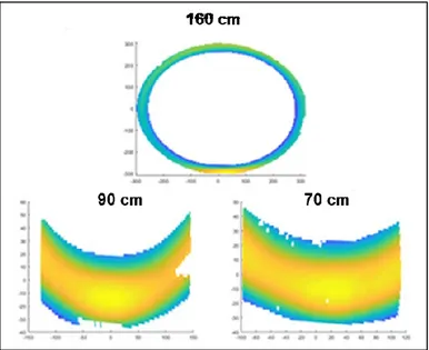
Figure 28 - Mode shapes comparison: LDV on the left side and DIC on the right side ... 37 Figure 29 – Static VS Rolling excitation ... 38 Figure 30 – Comparison of measurement areas for three different distances between cameras
and tire sidewall ... 39
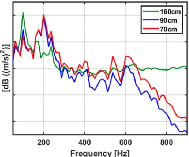
Figure 31 – Comparison of the average out-of-plane velocity Autopowers: effect of the
measurement distance ... 40
Figure 32 – Regions of interest comparison ... 41 Figure 33 – Comparisons of the average out-of-plane velocity Autopowers obtained
processing different areas or with different framings ... 42
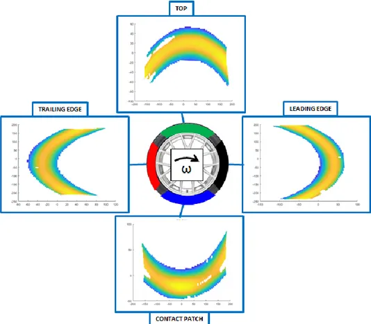
Figure 34 – Visualization of the measurement regions defined on tire sidewall ... 43 Figure 35 – Comparison of the average out-of-plane velocity Autopowers: contributions of
different sidewall regions (DIC case) ... 44
Figure 36 – Division of the LDV measurement grid in sectors to compare the DIC
measurement on different sidewall’s regions ... 45
Figure 37 – Comparison of the average out-of-plane velocity Autopowers: contributions of
different sidewall regions (LDV case) ... 46
Figure 38 – Comparison of the average out-of-plane velocity Autopowers: effect of subset
size (dynamic case) ... 47
Figure 39 - Comparison of the average out-of-plane velocity Autopowers: effect of subset
size (static case) ... 48
Figure 40 – Comparison of the average out-of-plane velocity Autopowers: effect of time
histories length... 49
Figure 41 – Framing optimization to increase the number of acquired frames... 50 Figure 42 – Sketch of voids effect on tracking in the crown area ... 52 Figure 43 – Comparison of the average out-of-plane velocity Autopowers: effect of
uncorrelated frames ... 53
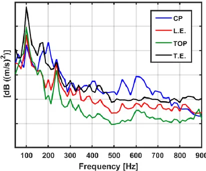
Figure 45 – Comparison of the contributions of tire TE, LE and Sidewall in terms of
out-of-plane velocity Autopowers ... 55
Figure 46 – Average out-of-plane velocity Autopowers of a rolling tire and background noise ... 56
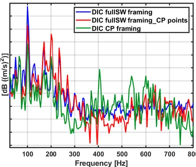
Figure 47 – Comparison of the average out-of-plane velocity Autopowers between DIC and LDV with full-view framing ... 57
Figure 48 – Comparison between DIC and LDV in terms of average out-of-plane velocity Autopowers after set-up optimization; the right-side figure is a zoom in the frequency range of interest ... 58
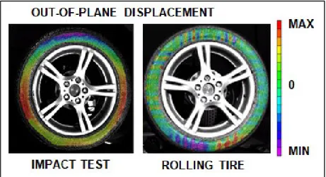
Figure 49 - Average Autopower of the comparison between impact test and rolling tire .. 59
Figure 50 - Comparison of mode shape of the same tire tested in static and rolling condition ... 60
Figure 51 – Effect of stiffer sidewall on the average Autopowers of the out-of-plane displacement of the sidewall ... 63
Figure 52 – Effect of stiffer sidewall on the average Autopowers of the out-of-plane displacement of tread area ... 63
Figure 53 - Comparison of sidewall and crown mode shape at 600 Hz to visualize the difference in terms of displacement amplitude ... 64
Figure 54 – Directivity of tested tires ... 65
Figure 55 – Effect of stiffer sidewall on noise emission for the microphone in which there is the main difference ... 66
Figure 56 – Effect of stiffer sidewall on the average of all the microphones of the array .. 66
Figure 57 – Effect of tread change in terms of sidewall vibrations: comparison of the average displacement Autopowers ... 68
Figure 58 – Effect of tread change in terms of crown vibrations: comparison of the average displacement Autopowers ... 68
Figure 59 – Effect of tread change in terms of noise emission: average of all the microphones of the array ... 69
Figure 60 – Directivity comparison for the tested tires in the frequency range 0 - 2000 Hz ... 69
Figure 61 – Average Autopowers of vertical in-plane displacement ... 70
Figure 62 – Sketch of the experimental set-up for the characterization of tire samples ... 74
Figure 63 – Post-processing flow ... 75
Figure 64 – 2D displacement map of tested samples (left); on the right there is the 3D visualization of the same sample to highlight the not flat shape of the sample and localization of the excitation ... 76
Figure 65 – Sketch of sample structure... 77 Figure 66 – Average FRFs of the tested samples ... 78 Figure 67 – 2nd bending mode visualization ... 79 Figure 68 – Out-of-plane displacement Autopowers of three points of the reference sample
... 80
Figure 69 – Comparison of load cell signals ... 81 Figure 70 – Comparison of displacement Autopowers obtained considering only the
centreline of each slab ... 82
Figure 71 – Focus on the first resonance ... 82 Figure 72 – Sketch of the samples used in the second case study where are indicated the
components considered in the table ... 83
Figure 73 – Effect of skim change: out-of-plane displacement Autopower comparison .... 84 Figure 74 – Effect of cord change: out-of-plane displacement Autopower comparison .... 85 Figure 75 – Effect of mixed skim and cord change: out-of-plane displacement Autopower
comparison ... 86
Figure 76 – Sketch of final samples with belt layer ... 87 Figure 77 – Comparison of the out-of-plane displacement Autopower for the tested samples
described in Table 4 ... 90
Figure 78 – OMA on samples A and B ... 92 Figure 79 - Mobility comparison for the first two bending modes of samples A and B ... 92 Figure 80 - Analysis of acoustic measurement and dynamic characterization of tires and tire
List of Tables
Table 1 – Frequency comparison of the identified modes ... 36
Table 2 – EMA VS OMA in the case of impact test ... 59
Table 3 – Features of the samples used in the first case study ... 78
Table 4 – Features of samples tested in the 2nd case study ... 83
Table 5 - Final samples configuration ... 89
Table 6 – Belt packages comparison ... 89
Chapter 1.
Introduction
The reduction of the noise generated from a rolling tire is becoming more and more important and it is probably the biggest and the most difficult challenge for tire designers because it is not easy to understand how noise is generated and which countermeasures can be adopted to reduce or control it. During last years, there has been a growing interest on this topic that has become one of the main performances considered during the development of a new tire. Until a few years ago, tires were developed trying to find the optimal balance between the main performances, such as dry handling, wet braking or low rolling resistance, and silence was an optional. If there were some noise problems, for example related to a car manufacturer’s claim, the problem was solved with some design changes. The approach to the problem was empirical and based on slight changes in the design of tire pattern and every claim had an ad hoc solution. Nowadays, the scenario is completely different both for the new severe acoustic limits imposed by regulations and for the NVH requirements coming from car manufacturers. According to these new requirements, tire industry understood that the unique way to produce a silent tire is considering this feature since from the first stages of the development, studying a tire structure that is also noise-oriented in addition to all other standard performances. So, in order to design silent tires, it is necessary to understand how tire noise is generated.
Even though a lot of researchers have worked on this topic, the phenomenon is still not completely understood because it involves several mechanisms which interact with each other. The complexity of the phenomenon is well described by Figure 1.
Although the noise source is the same, i.e. the rolling tire, two noise components are generally distinguished: in-vehicle noise and exterior noise. The in-vehicle noise is the noise perceived inside the car; the exterior noise is the noise heard by the people outside the car, i.e. the noise propagated by the tire in external environment. In-vehicle and exterior noise are two completely different phenomena as can be seen from the spectra shown in the lower part of Figure 1: the exterior noise has a strong contribution at high frequency, while the in-vehicle noise decays above about 250 Hz. This difference depends on the nature of the phenomenon considered. The exterior noise depends only on the rolling tire while the in-vehicle noise depends on the interaction between tire and car which acts like a filter or an amplifier according to the frequency range: the noise reduction at high frequency is related to the cockpit insulation, while the amplification at lower frequency depends on the coupling of tire vibrations with car components (more details in Chapter 2).
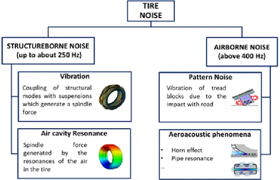
In addition to this, a second classification must be done considering the mechanism involved in the noise generation. According to this classification, Structureborne noise and Airborne noise can be distinguished [1], as described in Figure 2.
Figure 1 – In-vehicle and Exterior noise spectra of a rolling tire
The so-called Structureborne noise is related to the spindle force generated by the interactions of tire and vehicle’s components, such as the suspensions. The spindle force can be generated by:
• the coupling of tire carcass vibration with car suspension; • the resonance of the air cavity enclosed between tire and rim.
The Airborne noise, instead, depends on the interaction between tire and road because, when the tire is rolling, the impacts of the tread blocks cause high frequency vibrations. Moreover, there are some aero-acoustic effect like horn effect or pipe resonances in the grooves of the tire responsible of the high frequency noise. The airborne component is mainly responsible of the exterior noise, but it generates also an annoying high frequency noise component that enters inside the cockpit.
It must be also considered that tire structure is very complex because it contains rubber and cords of other materials and their combination determines tire behaviour: this makes the understanding of noise generation mechanisms quite tough and, therefore, the definition of general rules for tire design become a difficult task.
From this short introduction, it is clear how complex the phenomenon analysed is and why both the regulations and the car’s manufacturers require silent tire. From one side there is the car industry which requires silent tires because, over the years, ever higher levels of comfort have been reached inside the car through soundproofing of the cockpit that reduces the noise coming from the engine. Since the second main noise source on a car is the rolling tire, it can be easily understood how there is the requirement of quieter tires and this aspect will be more and more important with electric engines. The noise generation from the interaction of rolling tires with the road surface is the dominant source of vehicle noise for driving speeds above approximately 50-60 km/h for passenger cars [2], [3]. With new hybrid and electric engines, the effect is even amplified since the main noise source is removed.
On the other side there are the new regulations in terms of noise pollution reduction that impose a drastic tire noise abatement for the next years. Noise resulting from road traffic has a severe impact on the environmental quality in urban areas all over the world. In the European Union, it is estimated that approximately 80 million people are exposed to unacceptably high noise levels [4] and tire is one of the causes.
Moreover, it must be considered that, in order to produce “eco-friendly” tires, there is a progressive mass loss because of rubber reduction with an increase of the noise emitted: the vibrations of the modern lightweight tires are amplified due to the reduction of the damping material and consequently the noise emitted is magnified.
Another problem in the development of a noise-oriented tire structure is the absence of a dynamic characterization of tire materials that make impossible to predict if a material changes in one of the several layers making up the structure can be positive or negative in terms of noise emission. Nowadays the unique way to know the effect of a material change is the construction of a prototype and the execution of an acoustic test. This procedure is very expensive both in terms of money and time, because if the engineer must decide among several different technical solutions, it is necessary to produce a tire for each technical specification and execute a lot of tests. In this PhD project, a new approach based on the dynamic characterization of new tire samples is proposed in order to facilitate the material selection: the idea is to use the new characterization to select a small group of promising samples among a large group of materials and produce a smaller number of prototypes reducing the costs and the number of tests on tires.
This work focuses on tire and tire component vibration as noise generating driver. Since tire vibrations involves low and high frequency phenomena, an experimental characterization of tire and tire materials requires first of all the identification of a measurement technique able to cope with this frequency range (10 – 800 Hz) and with highly dynamic vibration amplitudes.
The aim of this PhD project is the understanding of noise generation mechanisms related to tire vibrations through the characterization of tire and tire components in order to define the guidelines for the design of the silent tires.
To dynamically characterize the rolling tire, an innovative measurement set-up for vibration measurement has been developed, optimized and validated both in static and dynamic conditions as well as the measurement procedure. The set-up is based on the
3D-Digital Image Correlation (DIC) technique to overcome the limits of the current state of art
techniques for this kind of measurement, as described in detail in Paragraph 2.3. The new set-up has several advantages, among which the measurement on tire tread can be considered as the most important innovation introduced by this work. The new set-up can be useful also for other activities, such as the validation of the Finite Element Method (FEM) models of tires or using the vibration maps obtained by a DIC measurement as input for the simulation of the radiated noise.
The same set-up is used to characterize the dynamic behaviour of tire samples in terms of mobility to define a criterion for a noise-oriented material selection. In this way the effect of tire vibrations on noise is studied from a global point of view (rolling tire) and a more detailed point of view (vibration of a single component/layer). The rationale behind this PhD project is illustrated in Figure 3 where the parallel strands are introduced.
According to Figure 3, the thesis is organized in order to describe the two mainstreams.
Chapter 2 is the introductory chapter, so it is divided into several sections each of
which describes a topic to give the reader a global point of view of the problem. In fact, the first section introduces tire structure in terms of its most important components; the second one describes the current status in the comprehension of the noise mechanisms with a brief description of them. The state of art techniques regarding the measurement of the vibrations of the rolling tire are introduced, analysed and compared in the third section as well as the innovative approach used in this work based on DIC technique. The fourth section deals with a focus on the state of art regarding the dynamic characterization of the materials highlighting which are limits related to a separate characterization of rubber and reinforcing cords. In the same section the new cord-rubber composite characterization is presented. The following section is dedicated to a brief theoretical introduction on DIC and the explanation of the different algorithms used and in the last paragraph the test benches used are described.
Chapter 3 is divided into two main parts. The first one describes what has been
done to optimize the new 3D-DIC measurement set-up, describing which are the best configurations both for sidewall and crown measurement, both in static and rolling conditions. The chapter contains also the validation of the DIC technique made by a comparison with LDV both for the static and the dynamic case. The second part presents two case studies to describe the main outcomes of this works and how it can be obtained with two different technical solutions, because in one case a sidewall construction change is considered, while in the second one a crown change is applied, but the effect produced is the same.
Chapter 4 deals with the optimization of the 3D-DIC set-up to measure the
vibration of tire slabs and a case study is described. The optimization of the measurement set-up, in terms of measurement technique is not described in detail, as done for the rolling tire case, because the static measurement and the experience of the author made the process of finding the best measurement conditions quicker. It was more difficult to find the optimal geometry and configuration of the samples, so this process is widely described concluding with a test case on the final samples. In the final paragraph the noise-oriented material selection is validated considering a test case in which acoustic and vibration measurements on tires are compared with the dynamic characterization of the new tire samples.
Chapter 5 states the main conclusions of the work, defining which goals have been
achieved and which can be the next step for further developments of the technique.
All the measurements have been performed in the facilities of Bridgestone NV/SA Technical Center that is a co-financier of the PhD project. The acquisitions are performed by the Correlated Solution VIC-3D software and the post-processing is made through some Matlab scripts developed by the author to obtain the displacement or velocity spectra, the ODS or to convert the DIC data into a format file compatible with TestLab that is used to perform the modal analysis of both the tires and the tire samples.
Chapter 2.
Theoretical background
2.1. Tire structure
In this short paragraph, tire structure is briefly described just to introduce the main components involved in this study. A car passenger tire must carry out several tasks such as providing the contact with the road, absorbing road irregularities and supporting vehicle load. All these tasks are demanded to sidewall and tread of the tire: the lateral surfaces of the tire are called sidewalls, while the tread or crown is the circumferential surface entering in contact with the road.
The main components of the tread area are illustrated in figure:
Figure 4 – Tire tread components [5]
• grooves: spaces between ribs needed for water evacuation;
• sipes: cuts in tread blocks for water evacuation and biting edges on road
surface:
• tread blocks: their sequence and shape define the pattern design and have
a strong influence on wear resistance, stability and traction;
• shoulders: connection point of sidewall and tread. Sometimes the shoulder
tread block can have a special design for a better traction.
Tire structure is very complex because it is made of a series of layers having a well-defined function. In this work (Chapter 4) the belt package and the cap ply are considered. In Figure 5 a typical section of a radial tyre can be seen.
Figure 5 – Radial tire structure with a zoom on cord-rubber composite layer [6]
All the following information come from the reference book “Pneumatic Tire” [7] that can be used for further details.
Radial tires are so called because they have body ply cords that are laid radially from bead to bead, nominally at 90º to the centreline of the tread. The main components are:
• Body ply layer. It is made of a rubber skim coating that encapsulates the radial ply reinforcing cords. It is a calendred sandwich of two rubber layers and a reinforcing fabric. Body plies provide the strength to contain the air pressure and provide for sidewall impact resistance.
• Cap ply layer. It is made of rubberized parallel cords of reinforcing fabric wrapped circumferentially over the steel belts and under the tread. It is a mechanical device that restricts the amount of growth due to the centrifugal load on the tire [8]. • Belt package. It is made of steel cords and rubber layers. The belt skim is the rubber
coating for the brass plated steel cords. The skim is calendered or extruded onto the steel cord in sheets and it is primarily formulated to resist fatigue and tear. Usually two or three belts are applied at opposite angles to one another on top of the body plies, under the tread area. They restrict expansion of the body ply cords, stabilize the tread area and provide impact resistance. Varying the belt widths and belt angles affects vehicle ride and handling characteristics.
Figure 6 – Body Ply and Cap Ply sketch [8]
2.2. Noise generation mechanisms
In Figure 2 some of the main noise generation mechanisms have been introduced. In this section a brief description of them is provided. The relative importance of each mechanism is a function of several system variables, including tire characteristics, pavement surface characteristics, environmental and interfacial characteristics [9]. According to Sandberg and Ejsmont [10], independently from the frequency range, the mechanisms can be classified into two main groups, the vibrational and the air-related ones. In addition, there are also some amplification or reduction mechanisms that must be considered. During rolling, the tire is subjected to radial vibrations due to tread impacts: after the impact, the tread is pushed toward the tire rotational centre, it stays in this deformed configuration until the contact with the road is not released: in this moment it starts to oscillate to return to its initial position. These are the low frequency vibrations generated by the impact mechanism: it happens at the leading edge and the resulting vibrations involve the entire tire carcass. At higher frequencies the vibrations are generated by:
• pattern impact: impacts of tread blocks causing radial and tangential
vibrations of tread blocks spreading to the sidewall;
• stick/slip: relative motion between tread elements and asphalt causing
tangential vibrations;
• stick/snap: adhesive effect of tire rubber with the road giving either
tangential or radial vibrations: at trailing edge each tread block is strongly deformed due to the adhesion between rubber and asphalt, so the contact release between tire and road is brutal causing blocks vibrations.
The high frequency noise is strongly influenced also by the aerodynamic mechanisms. The most important are:
• air turbulence: turbulence around tire due to the tire displacing air when
rolling on the road and air dragged around the spinning tire [10];
• air-pumping: air displaced into/out of cavities in or between tire tread and
• pipe resonance: air displacements in grooves of tread pattern amplified by
resonances [10];
• Helmholtz resonance: air displacement into/out of connected air cavities in
the tire tread pattern and the road surface amplified by resonances [10]. As regards the amplification or reduction effects, the most important of them are the air cavity
resonance (low frequency) and the Horn effect (high frequency). Between the curved tire
tread and the road there is a space which forms an acoustic horn that increase the radiant efficiency [11].
All the mechanisms can be schematised according to the following chart providing an overview of the phenomenon.
Figure 7 - Noise generation mechanisms chart
TIRE
NOISE
GENERATION MECHANISMS VIBRATIONAL IMPACT MECHANISMS TREAD IMPACT PATTERN IMPACT RUNNING DEFLECTION ADESHION MECHANISMS STICK/SLIP STICK/SNAP AERODYNAMICAL AIR TURBULENCE AIR-PUMPING PIPE RESONANCES HELMHOLTZ RESONANCE AMPLIFICATION OR REDUCTION EFFECTS HORN EFFECT THE ACOUSTICAL IMPEDANCE EFFECT THE MECHANICAL IMPEDANCE EFFECT TIRE RESONANCES BELT RESONANCES TOROUS CAVITY RESONANCESThe previous figures are graphic representation of all the mechanisms previously introduced. In this work the attention is focused on the tire vibrations as main vector in noise generation.
2.3. Vibration measurement on rolling tire
Even though there are several noise generation mechanisms, the dominant one for a rolling tire below 1 kHz is the tire sidewall vibration caused by collisions between the tread blocks and the road [12], [13]. This statement is confirmed by Winroth et al.: in their work, they study the dependency of air-pumping (aerodynamic effect) and tire vibrations with speed and state that an important component of U4 is found in measured tire/road noise on rough
road surfaces where it is expected that the noise is mainly generated by tire vibrations, not air-pumping [14]. The air related phenomena are usually considered as amplification factors. As stated in section 2.2, tire vibrations are different according to the frequency range: at low frequency (up to 250Hz) there are the carcass modes which involves the whole structure and are characterized by high amplitude displacements while in the high frequency range there are the vibrations responsible of the so-called pattern noise. In this case, the displacements are smaller and are strictly localized in the contact patch area, i.e. where there is the contact between tire and road. The impacts of tread blocks with the road cause first of all the vibrations of the blocks themselves and in turn the vibration of a small portion of the tire closer to the contact patch. The frequency depends on the rolling speed, the number of tread blocks and the pattern sequence. Tire tread pattern is made of blocks of different length to avoid the contemporary impact of the blocks with the road. The randomization of tread blocks is a common and efficient method used by tire manufacturers for reducing the tonal components in the noise. The idea is to distribute the energy over a larger frequency range, which gives a flatter sound response curve. Usually three or four different pitch lengths (the pitch length is the circumferential length of a shoulder tread blocks) are placed around the circumference of the tyre in an optimized sequence [15].
Figure 10 – Totally even pattern, no randomization (left); totally random shoulder blocks (center); optimized sequence of three pitch lengths (right). [15]
For this reason, the noise spectrum of a rolling tire does not have a peak corresponding to a certain frequency (there would be with equal length blocks) but there is a large “noisy area” with lower amplitude. In this way the overall noise level is reduced. The same happens for the vibrational spectrum. In the next figure, on the right side is presented the vibrational spectrum of a tire rolling at 80kph: the high frequency vibration is spread in a wide range (500 - 700 Hz); on the left is presented the effect of an optimized randomization (dashed line) and a mono-pitch sequence (black continues line).
Figure 11 – Effect of pattern randomization on noise (left) [15] and vibration (right) If the correlation between noise emission and tire vibration wants to be investigated, it is necessary to characterize the rolling tire. It should be pointed out that measurements on rolling tire are quite complex to perform for several reasons, first of all the tire itself. Tire structure is very complex, because it is made by rubber, that has a strongly non-linear behavior, and other material like nylon, steel, PET, Aramid, Kevlar, fiberglass and others whose coupling determine the global characteristic of the tire. Moreover, the measurement must be performed on a moving target and it is another complication because it reduces the number of instruments and techniques suitable for this application. For sure it is necessary to use a non-contact technique. To be honest, it is possible to develop a set-up based on the accelerometers, but it is easy to use only in static condition. Abd_Elsalam et al. [16] perform an experimental modal analysis on a non-rolling tire using a dedicated set-up suitable to vary some parameters and study their effect on the natural frequencies of the tire measuring the response of tire surface to the impact excitation using some accelerometers. In [17] the author performs the modal analysis of a loaded tire to evaluate the load effect with respect to a free-suspended tire. Yam et al. carry out a modal analysis on tire measuring the accelerations in all the directions and they were the first to obtain mode shapes in the radial, lateral and tangential direction [18]. Rocca et al. compare all the techniques defining advantages and limitations of each technique considering static and rolling measurement and they study the effect of the rolling speed on the natural frequencies comparing a static measurement made by accelerometers, with a rolling measurement in which an LDV is used [19]. Périsse uses a rotating signal transmitter to measure the acceleration of tire tread and sidewall with sensors put inside the tire to perform a vibration analysis of the rolling tire even if the number of
measurement points is very low. According to his measurement, the waves generated in the contact patch area are responsible for the noise radiation [20]. A similar work is presented in [21] where an electrodynamic shaker is used to excite a suspended tire, instead of the hammer. In rolling condition, the slip-ring could be used. A slip-ring is made of a rotor, which contains the sensors and is fixed to the rolling surface, and a static part, collecting all the cables. The biggest problem is the duration of the measurement: usually slip-ring have a small number of accelerometers, but in order to perform a significant measurement an high number of measurement points is needed, so it means that it is necessary to use a “start and stop technique”, i.e. the measurement must be interrupt several times to move the accelerometers to different positions. In this situation the stationarity of measurement set-up and boundary condition is not guaranteed. Moreover, the slip-ring should be fixed to the rim, so it means that there is an addition of mass to the tire/rim system that could affect the natural frequencies of the assembly, especially in rolling condition. The first paper on this topic has been published in 1990. In this work, the time histories of sidewall accelerations measured on the sidewall of a rolling tire were analyzed in the frequency domain [22]. A system like this can be used only on the sidewall. There are few works in which micro-accelerometers are placed in the groove of the tire in order to measure the vibration of the crown: in [23] this configuration is used to perform a vibration measurement in the contact patch area to provide useful data for the experimental verification of the analytic and Finite Elements Method (FEM) models used to simulate and predict the tire tread vibrations in order to study the noise generated when the tire pass over contraction joints in Portland cement concrete pavements. In many cases the slip-ring set-up is used to perform other kind of measurements on a rolling tire and they are often mounted in the inner liner of the tire, that is, inside it. In [24] three three-axis accelerometers fixed on the inner liner of a tire are used to detect friction potential indicators on two equally smooth surfaces with different friction levels to provide a direct tire-road contact friction estimation that is essential for the autonomous cars and active safety system. Xiong and Yang in their work [25] confirm the possibility to use such set-up to obtain a lot of information about tire/road interaction by mounting it in the inner liner. This could be used also to measure vibrations, but it will be a very long procedure because the tire should be removed from the rim several times. Vercammen et al. use the accelerations measured in the inner liner of the tire to obtain the so-called dispersion diagrams, comparing experimental results with the simulated ones, in order to study the effect of rolling speed. The results show that a rotating tire is subjected to Coriolis accelerations which make the wave speed of the positive- and negative-going wave to diverge from each other. This leads to an asymmetric shape of the dispersion curves, while the dispersion curves of a non-rotating tire are symmetric with respect to the zero-wavenumber axis [26].
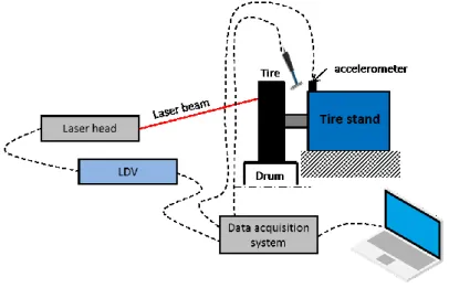
For sure the accelerometers are the most suitable sensors for a vibration measurement, but they have so many complications and limitations. For this reason, in literature can be found a lot of works in which this kind of measurement is performed by laser sensors and in most of the cases by means of a Laser Doppler Vibrometer (LDV). The LDV can be considered the state of art for this measurement for its several advantages: it is a non-contact technique, so there is no need to have a sensor placed on the measurement surface, it is possible to measure on a moving or rotating target surface and its high sensitivity allows to measure in a wide frequency range, that is probably the most important feature in accordance with the above. It has also some limitations, such as the need of a sufficiently homogeneous and optically cooperative surface, making impossible the measurement on the crown of a
patterned tire: the discontinuities generated by tread blocks and the other pattern features generate spikes in the signal when the laser spot passes through. Another potential disadvantage is related to the long measurement time, depending on the number of points to be acquired. Taking into account that the greater the number of averages, the lower the noise level, it is easy to understand that a measurement made by an LDV can be very long. For these reasons the stationarity of all the parameters influencing the measurement cannot be guaranteed when the tire is rolling: tire temperature and inflation pressure can change and an increase in tire temperature could change the response of tire materials. In literature can be found a lot of works in which the LDV is used to measure tire vibrations for several applications. Matsumoto et al. use a laser sensor installed on a wheel to measure tread displacement and evaluate the high-frequency vibrations of a tire when it passes over a cleat [27]. Rocca et al. [28] published a second paper dealing with the main experimental activities and modal analysis techniques available nowadays for characterizing the dynamic behavior of a static (unloaded and loaded tire on a fixed hub) and rotating radial tire under different boundary conditions (rolling speed, inflation pressure, preload, temperature and excitation). In the same work they identify the modes of a rolling tire using a typical test bench made of lens for LDV orientation and a cleat mounted on a rolling drum for the excitation (the set-up is presented in Figure 12). This set-up can be used to also measure the crown, but the tire is slick, i.e. it does not have the pattern, and for this reason a cleat is needed to excite the tire (more details on this topic are provided later in this paragraph). Castellini uses two different approaches to measure the sidewall vibrations: in [29] a Lagrangian approach is used because the laser spot tracks a single point along its trajectory unlike the second in which the laser spot is fixed and the tire surface flows under it (Eulerian approach) [30]. According to the approach, different phenomena can be detected: with the Eulerian approach it is possible to detect only vibrations associated with waves travelling in the laboratory reference system, while it is not possible to detect counter-rotating vibration waves that determine fixed figures and shapes [30]; with the Lagrangian approach it is possible to detect only vibrations associated with waves travelling in the rotating (synchronous with the tire) reference system. Standing waves moving with the tire cannot be detected [29]. In [31] a Scanning LDV is used to measure the vibration of the sidewall of a rolling tire mounted on a particular test bench. In [32] the LDV is used to measure the vibration of sidewall and crown of a slick tire using a tire-on-tire set-up and a cleat to excite the tire and simulating the excitation coming from road discontinuities. The data generated by an LDV measurement can be post-processed in different ways: they can be used to perform an Operational Modal Analysis (OMA) [33] on the rolling tire [19], [32]; obtain the Operational Deflection Shapes (ODS) [30]; study the correlation between tire vibration and noise in rolling condition [21]; generate the dispersion diagrams [34] in which Bolton and Kim introduce also the wavenumber domain decomposition of tire vibrations or compare the numerical and experimental dispersion diagrams [35]. Once again, the measurement is performed with LDV and a cleat is needed to excite the tire. The dispersion diagrams in rolling condition show how the effect of rolling speed is the loss of symmetry in the wave propagation due to Coriolis accelerations which make the wave speed of the waves travelling in opposite direction of the tire rotation to diverge from the speed of the waves travelling in the rotation direction [35]. This effect has been confirmed in [36] in which the authors use the LDV data to develop a model of tire based on thin cylindrical shell theory to evaluate the effect of rotation. They found that the
same shape of traveling-wave modes occurs for a rolling tire and that the excitation frequency of the forward wave is different from the backward wave.
LDV is used also to compare the vibrations levels of Trailing Edge and Leading Edge of a rolling tire by a crown measurement on a slick tire [37]. A system with mirrors is used to guarantee the perpendicularity of the laser spot with tread surface and according to the authors the Leading Edge vibration level is higher than that of Trailing Edge and tread vibration is influenced by belts. A slick tire is also used by Kindt et al in the reference paper for this kind of measurement. Using a special tire on tire test bench, with a cleat exciting the rolling slick tire and an LDV to measure tire response, in [38] the sidewall response is measured to evaluate the influence of some parameters (inflation pressure, rolling speed and cleat height). The same set-up has been used to measure both on sidewall and crown and the authors were able to identify the modes performing an OMA [39]. The same set-up is also used to perform an OMA on the rolling tire excited by the cleat to compare the data with the static case. In the same time an acoustic measurement is performed and a correlation between some acoustic peaks and vibrational modes has been found [40].
Figure 12 - Innovative test benches for measurements on rolling tires excited by cleat mounted on the drum (left) [28] and on tire-on-tire setup
Moreover, in [41] the LDV is used to perform a particular measurement: it is used in two different set-ups developed to measure the in-plane vibrations of tread blocks. The measurements allow to highlight and separate the frequency ranges related to carcass and tread blocks vibrations.
The limits of the LDV can be overcome with the Digital Image Correlation (DIC) technique. It is an optical technique, so it has all the advantages of a non-contact technique, but it is a full-field technique, so it is possible to acquire a high number of synchronous points unlike the LDV where an external sensor is always needed for the phase realignment of the signal of each point because they are acquired in different times. DIC technique is quite simple: it compares a reference image of the measurement surface with an image of the surface deformed to define the displacement of the measurement points. Since it works on displacements, it has a lower sensitivity if compared with LDV and this aspect made the
technique not suitable for a vibration measurement, especially in those cases in which there are high frequency vibrations that are characterized by very small displacements and this technique cannot detect them. The recent developments of modern fast cameras made possible to measure very small displacements, so this technique could be suitable for this kind of measurement, because it is possible to have sensor with quite high resolution and very high frame rate. Moreover, the DIC technique can be used also to measure the vibrations on the tread of a patterned tire. The confirmation of the possibility to use the DIC as a tool for vibration measurement can be found in literature: [42], [43], [44], [45], [46] are just some examples of works in which high speed DIC is used to measure vibrations of different objects and the results are compared and validated with classical techniques, such as accelerometers or LDV. The main difference with respect to the activity described here is the dimension of the target, because in the cited works the measurements are performed on simple and small objects. The target size is important because it defines the dimension of the image and in turn the resolution of the acquired images as well as the value of the smallest displacement measurable (more details in Chapter 3). A couple of DIC applications on tire can be found in literature, even if, according to author’s knowledge, there were no references on vibration measurements on rolling tire performed by DIC technique when this PhD project started three years ago. In fact, the DIC technique has been used for several applications: measure the longitudinal tire slip ratio [47]; analyze stick-slip behavior of tire tread blocks [48]; measure the strain of a rubber sheet deformed by air pressure supplied below the sheet to compare these results with FEA predictions or visualize the deformation of an AGR tire, i.e. the tire of an agriculture truck [49]. Only in recent times (April 2018) a work, in which DIC is used to measure the dynamics of a racing tire of a formula SAE car in static and rolling conditions, has been published [50]. The DIC set-up is used to measure the displacement and the strain variation of the sidewall of a tire mounted on a car and rolling on a drum. The results indicate also the resonant frequencies and some operational mode shapes are shown. In [51] the DIC set-up is used to measure the vibration of a free suspended tire excited by a shaker or a hammer. The set-up is moved in different positions to measure different sections and then they are stitched to reconstruct the entire tire. The authors propose an approach to identify a uniform scaling factor that enables them to stitch the operating shapes extracted from different views. The advantage of acquiring a lot of measurement points suggests using this technique also to validate the FEM model of tire structure or materials. This is what is described in [52] where the DIC system is validated through the testing of a simple thin, rectangular rubber sample and the results are compared with the simulated ones.
One of the main advantages of the DIC technique is the possibility to work with inhomogeneous and discontinuous surfaces, the only requirement is the possibility to print the speckle pattern on it. This peculiarity made the DIC capable to measure also the crown because the pattern does not create problems unlike the laser-based techniques. This is the main innovation introduced in this thesis as regards the dynamic characterization of rolling tire. As previously described, the measurement on crown have been performed also with LDV, but only on slick tire excited by a cleat. LDV, in fact cannot measure a tire with pattern, but the excitation coming from the road it is not high enough to generate appreciable displacement on crown, so a cleat is needed. With DIC it is possible to measure a real pattern tire and the comparison these vibrations with those of sidewall provide useful information.
modes or groups of modes in the frequency range around 1 kHz that have small amplitude, but high radiation efficiency and they are mainly responsible for the noise emission [53]. Until a few years ago, the application of DIC as vibration tool was limited in terms of frequency range because the available cameras had low frame rate. The modern fast cameras have very high frame rate and a resolution such that the small displacements characterizing the high frequency vibrations can be detected.
2.4. Tire components characterization
The previous section, dealing with the state of art techniques in terms of vibration measurement on rolling tire, describes how the characterization of a rolling tire has been done in the past and briefly introduces how it is performed in this work just to highlight the main differences with respect to the current state of art. The dynamic characterization of the rolling tire will be deeply described in the next chapter. In this section, the problem of the dynamic characterization of tire components is introduced with the analysis of the available techniques and the limits of the current characterization.
2.4.1. An innovative approach to tire noise
If the understanding of noise mechanisms is complex, the evaluation of the effect of a single tire component on the overall noise is even more challenging. It depends on the complex tire structure, the coupling of the several materials used and the way in which different layers interact with each other.
One of the main difficulties in studying tire noise is the need of an experimental acoustic test on a prototype tire. In fact, there are no literature references or industrial know-how suggesting which material can be used to obtain a reduction of tire noise, so any time a variation is applied to tire structure, whatever it is, it is necessary to produce the complete tire and then test it. This procedure is too much expensive both in terms of money, because of the cost of tire testing and tire manufacturing, and time, considering the long time required to produce a tire and its testing. Moreover, the mechanism understanding of the noise generation process it is not increased and the effect of a single component cannot be evaluated because several solutions are proposed and the one giving the best result is chosen. In this way the problem is studied from a global point of view only.
In the second part of this work (Chapter 4), an innovative approach based on the dynamic characterization of tire components is proposed. The idea is to define a parameter which can be used for a preliminary selection of some materials belonging to a large group of proposals. The need for such characterization has emerged during the last couple of months of the PhD project. During this period, an activity to study the effect of different reinforcing materials on noise emission was started with the aim of finding which are the best materials for cords of cap ply and body ply. There was an evident difficulty in the choice of the
materials to be tested and as a consequence the number of tests was very high. The problem is the lack of a dynamic characterization of these components creating difficulties for material engineers which do not have adequate information to choose the materials. The available material characterization did not provide useful data since it is performed on small rubber samples (without cords) or in quasi-static conditions when sample contains also reinforcing cords: a load is applied and the deformation of the sample is measured to evaluate in-plane and out-of-plane stiffness. That’s the way things are, if the effect of different materials wants to be investigated, so many tires must be produced, one for each material.
Also in the project described here this approach has been used, but, once a group of materials have been selected and the corresponding tires have been realized, in parallel some samples of cap plies and body plies made of the reinforcing materials used on the tested tires have been produced, as if they have been removed from their position inside tire structure. Unfortunately, it is impossible to cut a tire and extract each component because the layers are welded to each other, so it is necessary to produce the samples separately even if it generates some problems (as will be discussed in Chapter 4). The samples have been characterized using an electro-dynamic shaker and the 3D-DIC set-up and these results have been compared with acoustic and vibrational measurements on rolling tires.
As previously said, the aim of this activity is to find a parameter of the samples useful in predicting the effect on noise emission of the real tire. Since it is a completely new activity, there are no references in literature or industrial know-how suggesting which aspect to consider and how to define if a material is better than another in terms of noise emission. For this reason, the adopted strategy is based on the comparison of noise measurements on rolling tires, dynamic characterization of the rolling tires and dynamic characterization of the samples. The analysis of the data suggest that the mobility of the samples should be the parameter to be considered: the cases in which rolling tire noise is reduced are those in which the crown is free to vibrate and being the crown behaviour determined by cap ply and body ply layers, it can be stated that the best solutions are those giving a high crown mobility. It may seem strange that a noise reduction can be achieved increasing the mobility of a components, but this is the experimental evidence (more details will be provided in the case studies described in Paragraph 3.5). To be honest, it must be specified that the number of tested samples it is not too high, so all the results must be confirmed and validated with further tests. A dedicated project building has been realized considering a certain number of tires and tire samples, but further investigations could be performed to consolidate the outcomes of this thesis.
This new approach represents a drastic change in the way the noise is studied: in the first stage of the analysis, tire noise is related to tire behaviour through a dynamic characterization in terms of crown and sidewall vibrations; in the next step, tire vibration is related to a single component through its dynamic characterization. In this way, a significant step forward beyond the current state of art can be done increasing the level of detail of the analysis.
The current and proposed approach are compared in the following figure.
Figure 14 - Comparison of current and proposed approach for tire components characterization Moreover, the new procedure reduces the costs of the development process as well as the devolvement times. Let’s imagine having to choose the reinforcing material among a large group of materials. The current approach can be described by the following steps:
• definition of a list of materials to be tested considering only the static characterization currently available;
• production of a prototype tire for each different material selected; • tire testing of all the prototypes;
• material selection made considering the tire that score the best results in terms of noise emission.
![Figure 5 – Radial tire structure with a zoom on cord-rubber composite layer [6]](https://thumb-eu.123doks.com/thumbv2/123dokorg/2971217.27314/29.892.199.734.323.597/figure-radial-tire-structure-zoom-rubber-composite-layer.webp)
![Figure 16 - Tanδ VS Temperature for different type of tire rubber [55] (left) and typical stress and strain curve of tire rubber and specimen geometry [58] (right)](https://thumb-eu.123doks.com/thumbv2/123dokorg/2971217.27314/44.892.211.734.673.850/figure-tanδ-temperature-different-rubber-typical-specimen-geometry.webp)