Ultrasound Guided Diagnostic and Surgical
Robots
a dissertation presented by Risto Kojcev toThe BioRobotics Institute
in partial fulfillment of the requirements for the degree of
Doctor of Philosophy in the subject of
BioRobotics
Scuola Superiore Sant’Anna Pisa, Italy
Ph.D. cycle XXIX
Tutor: Prof. Paolo Dario Advisor: Dr. Edoardo Sinibaldi
©May 12, 2017 – Risto Kojcev all rights reserved.
Abstract
This thesis describes the development of three robotic platforms for medical applications which enable humanrobot interaction for diagnostic imaging, surgical planning, and ultrasound (US) -guided procedures. A dual-robot framework for US--guided needle placement was designed with the aim to provide a solution that encompasses the difficulties in performing needle placement in specific surgical procedures such as cryoablation. The system capabilities were tested on water-and gelatin- phantoms which consisted of non-uniform structure to better simulate biological tis-sue. A novel framework for robotic-assisted US studies of the thyroid was subsequently developed for US monitoring of suspicious thyroid nodules. The system integrates RGB-D camera and US transducer, and allows supervised US acquisitions. This robotic solution overcomes the inconsis-tency introduced by the human factor during acquisition of US images, and solve a common clinical problem, where the diagnosis of suspicious thyroid nodules solely depends on hand-held US im-ages acquired over long span of time (up to couple of years). The system was tested on a group of volunteers. The study was approved by the Institutional Review Board (IRB), and conducted with supervision of medical expert. The results of this study proved the potential practical impact of the framework and its applicability. Finally, a tele-operated framework equipped for haptic feedback allowed preliminary test for transatlantic ultrasound acquisitions. All the systems were specifically designed to perform complex tasks of manipulation on difficult environment such as biological tis-sue, in a clinic scenario.Contents
1 Introduction 1
1.1 Medical Ultrasound . . . 1
1.2 Medical Robotics . . . 3
1.3 Ultrasound Guided Medical Bobotics . . . 4
1.4 Thesis Structure and Contributions . . . 6
2 Dual-Robot Ultrasound-Guided Needle Placement 8 2.1 Introduction . . . 8
2.2 Materials and Methods . . . 11
2.3 Experiments and Results . . . 19
2.4 Discussion and Conclusion . . . 23
3 Thyroid Ultrasound 26 3.1 Introduction . . . 26
3.2 Materials and Methods . . . 32
3.3 Experiments and Results . . . 37
3.4 Discussion and Conclusion . . . 41
4 Towards Transatlantic Ultrasound 44 4.1 Introduction . . . 44
4.2 Materials and Methods . . . 48
4.3 Results . . . 53
4.4 Discussion and Conclusion . . . 56
5 Conclusion 58
Ultra-A.4 Discussion and Conclusion . . . 76
Appendix B Development of a Flexible Probe 77 B.1 Introduction . . . 77
B.2 Methods . . . 79
Appendix C Achievements 83 C.1 Patents . . . 83
C.2 International journal publications . . . 84
C.3 International conferences: posters, extended abstract and papers . . . 84
C.4 Open Source Contributions . . . 85
Listing of figures
2.1 Common practice for performing radioablation, shown in a), and cryoablation,
shown in b) under ultrasound guidance. Image taken from [1]. . . 9 2.2 The workflow is organized in three phases: the initialization phase (red boxes),
ultrasound volume acquisition (blue boxes), and the US-guided needle insertion
(green boxes)[2]. . . 11 2.3 The transformations flange-to-cameraC{1,2}TF{1,2}, flange-to-needle tipNTTF2, and
base-to-baseB2TB1need to be calibrated, while the transformations base-to-flange F{1,2}T
B{1,2}are provided by the robot [2]. . . 13 2.4 Illustration of the proposed dual-robot concept in phantom experiments. While
one robot holds the US transducer, the second robot injects the needle. The point of injection is computed by intersecting the image plane with the patient’s surface. Additional constrains arise from collision avoidance and needle length. Needle tracking (yellow line) within the needle neighborhood (diagonal gray rectangular), as well as target tracking (red circle) under consideration of the target neigh-borhood (gray square) are explained in Sec. 2.2.4. The adaptive planned needle
trajectory is visualized in red [2]. . . 16 2.5 The experimental setup is comprised by two KUKA iiwa, holding the needle and
ultrasound transducer. After calibration of the base-to-base transformation, visual servoing is performed to place the needle in the target, which is observed in the
ultrasound image. . . 20 2.6 During needle placement the target ROI is continuously co-registered between
two sequential images to compensate for its motion. a) The red overlay displays the target in its initial position and the blue overlay after translational movement
of± 20 mm. b) The final registration result is shown. . . . 21
2.7 Needle tracking while approaching a target, in which the yellow line represents the fitted polynomial. The tracked tip (blue) and the user-defined target (red) are visible. 23
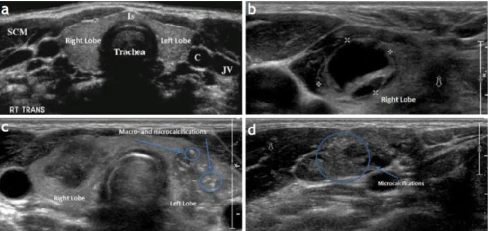
3.2 Anatomy of the Thyroid Glands in US images. a) Normal appearing glands, b) Complex most probably cystic thyroid nodule in the right thyroid lobe. c) Two large, hypoechoic nodules associated with poorly defined borders, the left-sided nodules showing macro- and microcalcifications. d) An abnormal lymph node, round in shape with microcalcifications that are very consistent with thyroid
metastasis[3]. . . 28 3.3 The left and the right lobe of the thyroid (illustrated in a) are measured and
inspected individually. During the standard of care, the expert acquires 2D ul-trasound images as seen in b). We hypothesized that the robotic ulul-trasound contributes in assisting image acquisition, and may lead to more reproducible
results. . . 30 3.4 The workflow is organized in three phases: the initialization phase (red boxes),
ultrasound volume acquisition (blue boxes), and the diagnosis and future actions
(green boxes) . . . 32 3.5 Chain of Transformation of robotic thyroid US. The robotic system provides
flange-to-base transformation based on the known kinematics. The camera-to-flange and US-camera-to-flange transformations need to be calibrated once before deploying the system, while transformations describing the relationship between
the system and the patient are computed in real-time. Please refer to text for details. 33 3.6 The robotic ultrasound system automatically acquires images from the thyroid
under expert monitoring. . . 39 3.7 Trajectory planning is performed using the live 3D point cloud data and the color
images from the RGB-D camera. The color images and the 3D point cloud data are displayed on the UI on the framework. The operator then can select ROI (shown as yellow rectangle) and a robot trajectory (yellow line) onto the patient
surface. . . 39 3.8 Measurements performed on the US Volume acquired by the robot. Illustrated in
a) is the acquired volume, in b) are measurements performed on the longitudinal and AP view of a thyroid lobe, and in c) are the measurements performed on the
transverse view. . . 40 3.9 Standard deviation of thyroid size measurements for each volunteer and on each
direction (AP, T, L) performed by the expert (yellow) and the robot (blue). Each bar represents the standard deviation for 6 measurements performed on the right and left lobes of each volunteer in the specified direction by either the expert or
robot. . . 41 4.1 Concept of the first transatlantic surgery. Image courtesy of IRCAD [4] . . . 45 4.2 RAVEN II Surgical Robot, University of Washington [5] . . . 47
4.3 Concept of our framework presented in local scenario. The master robot is freely moved while the slave robot imitates the movements of the master. The force exerted at the end-effector of the slave is continuously monitored. Once a force higher then force preset by the user, the movements of the master are limited in
order to maintain constant force on the patient surface and prevent injuries. . . . 53 4.4 First transatlantic test of the proposed platform. One of the robots was located at
Johns Hopkins University, Baltimore MD U.S.A. and one at Klinikum Rechts der Isar, Munich, Germany. The round-trip time was 94 ms. . . 55 A.1 (A) Platform overview: interventional module (needle steering device),
intraop-erative localization (optical tracker), intraopintraop-erative imaging (US transducer and operating lightweight robot). (B) US image registration: schematic of the main components and illustrative frames/transformation (UT: ultrasound transducer,
CS: calibration phantom, RB: robot base, RW: robot wrist). . . 65 A.2 US Transducer handling interface with a purposely designed multi-faced optical
tracking tool and a calibration phantom [6]. . . 66 A.3 Intervention module (needle steering device) (A) CAD model. (B) Fabricated
needle steering device . . . 67 A.4 System setup of the platform for ultrasound-guided interventions . . . 69 A.5 A) Calibration setup for US image. (B) Calibration phantom with wires. (C) 3D
reconstruction (example) of the calibration phantom wires . . . 70 A.6 Final design and electrical connections for the control components of the flexible
needle steering robot. . . 71 A.7 User Interface for establishing connection with the needle steering robot. . . 72 A.8 Flow diagram describing different state machines in our system. As seen the User
Application is able to Initialize the needle steering platform and set it in different states of operation. In case of error of the hardware components, the system goes
into Pre-Op mode which does not allow any movement of needle steering. . . 73 A.9 User Interface for jogging or setting initial position of the robot. . . 73 A.10 User Interface for duty-cycle control, reading current position and current
force/torque. . . 74 A.11 Output from an example duty-cycle control. The overall time was set to be 10
seconds, with the linear stage incrementally increasing its position (pushing the needle forward). The angular position changes based on the user input (positive
number clockwise, negative anticlockwise). . . 75 B.1 Schematic of the main probe components and exemplificative deployment
Acknowledgments
I would like to express my sincere appreciation and gratitude to Dr. Edoardo Sinibaldi, who has provided continuous support and encouragement for my research in collaboration with the Center for MicroBio Robotics at the Italian Institute of Technology, Pontedera Italy. I would like to thank Professor Dr. Nassir Navab for giving me the opportunity to carry part of my research in collabora-tion with Computer Aided Medical Procedures group, at Johns Hopkins University in Baltimore, Maryland, USA. Dr. Sinibaldi and Professor Navab guidance helped me in all the time of research and writing of this thesis. I would like to thank you for encouraging my research and for allowing me to grow as a research scientist.Furthermore I thank Professor Paolo Dario, the director of the BioRobotics Institute of Scuola Superiore Sant’Anna, Pisa Italy, for the possibility to be part of the Ph.D fellowship in BioRobotics.
I express my special appreciation and thanks to Dr. Kevin Cleary and Professor Dr. Gabor Fichtinger for reviewing my thesis and providing me with valuable feedback.
I would like to thank my colleagues Bernhard Fuerst, Oliver Zettinig, Sing Chun Lee, Khakzar Ashkan, Javad Fotouhi, Benjamin Frisch and Byungeon Kang for their assistance, fruitful discus-sions and continuous support.
A special thanks to my parents: Stanoja and Lidija, my brother Stefan, for their continuous en-couragement and support over the years. Last and not least I am grateful to my wife Sara who has been unequivocally and unconditionally supportive and who has provided me with the confidence to pursue my goals.
1
Introduction
1.1 Medical Ultrasound
The potential of ultrasound for exploring biological tissue raised human curiosity since early times. Ultrasound caught the attention of the Italian scientist Lazzaro Spallanzani (1729-1799) who first described the physics behind this phenomenon after observing how bats navigate by echolocation [8]. The technological challenge in reproducing ultrasonic waves limited the interest for ultrasound
phenomenon until the discovery of the Piezo-Electric effect by Pierre and Jacques Curie [9]. In 1915, Paul Langevin created the first ultrasound transducer [10] which in that time was used to detect icebergs and submarines. The discovery of the ultrasound transducer was indeed a milestone, but its usage remained confined in military applications for few decades. In 1945, ultrasound was first used for medical applications by the physician Karl Dussik, who employed ultrasonic waves to ex-plore brain tumors [11]. Since then, the role of ultrasound as a medical imaging modality became of crucial importance; ultrasound has now become an integral part of medical practice.
Modern US system can be used for imaging almost all soft tissue structures in the body. The ar-rangement of the piezo-elements in the 2D US transducer can be either linear, convex or phased [12]. In the recent years, more advanced US transducers have been introduced with the increase of num-ber of elements and diagonal beam-forming. However 2D imaging transducers have limited field of view and resolution, yielding images with varying quality.
To address the disadvantages of the limited field-of-view with the 2D US transducers, recent ad-vances in US imaging techniques have introduced 3D US transducers. One technique of acquiring 3D US imaging is by encapsulating a curvilinear transducer within a casing and automatically pivot it inside [13]. This allows construction of 3D US volume without the user moving the transducer. Newer generations of 3D US transducers are based on 2D arrays, in which broad US beam is emit-ted and the received signals are feed to several receive beam formers working in parallel [14]. These transducers are frequently used in cardiology where the view of the heart is restricted due to the rib cage. However the imaging area is limited to the pose of the transducer held by the user. A larger 3D volume can be acquired by moving the 2D transducer along the patient surface. In order to com-pound the volume from 2D US images, different tracking techniques such as infrared, optical, or
method commonly employed not only for diagnosis, but also for intervention applications.
1.2 Medical Robotics
The fundamental principle of robotic system is to transform a complex information into physical action. This ability to assist, replace, or perform tasks in a same way as the humans, has a profound influence in many aspects of our society, such as industrial automation, exploration, artificial intelli-gence systems, home assistants, and self driving cars. Although robots have first been introduced to replace simple repetitive task, their long term impact is seen as enablers of whole computer integra-tion of a entire process of producintegra-tion or service.
Medical robots share the potential to transform a medical practice from a strictly human ges-ture to a fully-robotic action driven by human, improving the dexterity and allowing for a more precise procedure. Furthermore, the repeatability and consistency of a robotic system can be easily integrated with computer-assisted information to provide a system that crucially contribute to the success of interventions. [16,17]. A typical work flow for a medical robotic procedure starts with the collection of preoperative information about the patient, which can be obtained with the aid of medical imaging techniques. Images obtained are either analyzed by the medical doctor, or by means of computer-assisted systems (which combines statistical models and deep learning tech-niques). Data obtained, range from physiological malformations, to the detection and localization of patient’s specific anatomy parts. Preoperative information is then combined with information gathered during the interventional procedure by means of image registration [18]. Preoperative and interoperative information are then aligned together, which is then used to plan and execute an action by the robot. If any condition changes during the procedure, the system should update and re-plan the robot trajectory. During the intervention, additional sensing or imaging is used to monitor the progress of the procedure, update the planned trajectory of the robot, and verify if the
planned procedure is successfully executed.
A wide range of robotic systems designed for specific clinical applications are available nowadays. The most adopted and commercially available system is the Intuitive Surgical’s da Vinci system. [19]. Other interesting solutions have emerged in the clinical practice such as Mazor robot for pedicle screw placement [20] or NeuroMate, a robotic solution focusing on neurosurgery applications [21]. Beside commercially available systems, there is a need for next-generation systems to fill the current technical limitation, such as advancement in autonomous motions, synergistic manipulation, and virtual fixtures. For a newly-developed medical robotic system to be accepted, significant benefits compared to traditional clinical methods [17] has to be proved. Taylor et al. [17] has classified the following characteristics of robotic system to be accepted and adopted into clinical practice: new treatment options, quality, time and cost, less invasiveness, safety, real-time feedback, accuracy or precision, enhanced documentation and follow up. The long approval time, preclinical studies, and the non-trivial challenge of integrating robotic solutions in the operating room has left many sys-tem only as a research projects which are unrevealed to the general public and not-yet implemented in clinical environment. Despite the intrinsic difficulty in bringing a prototype to a commercially available system, medical robotics can be considered as a driving research field, which can lead to significant technological advances even in different application fields.
1.3 Ultrasound Guided Medical Bobotics
Ultrasound is a commonly used imaging modality in the clinical practice today. Therefore, it is nat-ural to integrate ultrasound-based robotic solutions for interoperative guided solutions and preop-erative planning.
ing algorithms for detecting needle in an ultrasound image and for ultrasound visual servoing. In 2004, Hong et al. [23] developed an algorithm for detection of the needle in 2D ultrasound images. The platform required the needle to be aligned with the ultrasound transducer, which allowed the robotic component to insert the needle along the ultrasound B-mode plane, to target a region of interest in the image. Similar task was performed by Wei et al. [24], which targeted brachytherapy applications. While strongly focusing on the needle trajectory, the mentioned publications did not incorporate a moving (robotic) ultrasound acquisition. Therefore, they are limited by the field of view of the ultrasound transducer, and require manual re-positioning. A flexible-needle-guided sys-tem was developed by Abayazid et al. [25]. The system consisted of a two degree-of-freedom robot for flexible needle steering, and linear stages for controlling the movement of a 3D ultrasound trans-ducer. The proposed framework was successfully tested in the simplified experiments performed in laboratory; nevertheless, the methodology proposed is hard to apply in a clinical scenario due to limitations related to the robot kinematics (linear stages might not be sufficient to cover patient mo-tions realistically) and lack of force sensing. Chatelain et al. [26] proposed a dual robot system for ultrasound-assisted flexible needle insertion, with novel algorithms for needle detection, and confi-dence map ultrasound visual servoing. The platform was evaluated on water and gelatin phantom which did not present any obstacle to cross. This work provided novel insights into flexible needle ultrasound-guided procedure, and paved the way for further researches to focus on the develop-ment of strategies for a better integration of flexible needle insertion in realistic clinical scenario. More in general, the future perspective for ultrasound-guided medical robotics should consider (1) identification of specific application and (2) optimization of the data sharing process between the guidance and the imaging system. Toward this direction, the exploitation of open source platforms for image-guided interventions, which allow for a rapid implementation of applications [27], helped in establish a standard protocol of operation based on software frameworks such as OpenIGTLink [28] and the Plus Ultrasound Library [29].
Navigation is based on preoperative or intra-operative imaging combined with 3-dimensional position tracking of intervention tools registered to the images. Research of navigation technology in medical interventions requires significant engineering efforts. The difficulty of developing such complex systems has been limiting the clinical translation of new methods and ideas. A key to the future success of this field is to provide researchers with platforms that allow rapid implementa-tion of applicaimplementa-tions with minimal resources spent on reimplementing existing system features. A number of platforms have been already developed that can share data in real time through standard interfaces. Complete navigation systems can be built using these platforms using a layered software architecture.
The main contribution presented in this thesis focuses on the development of novel ultrasound-guided platforms that target shortcomings of the current state of the art systems, and aim at provid-ing practical solutions to specific medical applications which can be easily integrated in the operatprovid-ing room, and bring added value to the surgical procedure.
1.4 Thesis Structure and Contributions
Three different platforms that enable surgeon-robot interaction for diagnostic imaging, surgical planning, and ultrasound (US) -guided procedures are shown. The robotic systems were designed for applications which require for the robots to master complex abilities of manipulation in a con-text where the safety of interaction with the humans is crucial. For this purpose, a user-friendly in-terface to control and change a manipulator into Cartesian Impedance control mode was developed. The Impedance control platform, specifically designed to be used by medical staff, provided a valu-able framework for robots moving in unknown environment, and allowed to achieve a more precise
ment is presented in Chapter 2. The system was designed with the goal of providing a solution that encompasses the difficulties in performing needle placement in surgical procedures such as cryoab-lation and radiofrequency. Development of the dual-robot framework, including robot-to-robot interaction, US and RGB-D camera calibration, novel needle tracking algorithm, and volume com-pounding were completed. In Chapter 3, a novel framework for longitudinal studies of the thyroid which provides a solution for a US monitoring of suspicious thyroid nodules is shown. The system, which integrates RGB-D camera and US transducer for enabling user supervised US acquisitions, was designed to solve a common clinical problem, where the diagnosis of suspicious thyroid nodules solely depends on hand-held US images acquired over long span of time (up to couple of years). The proposed solution tries to overcome the inconsistency introduced by the human factor during ac-quisition of US images, which can lead to misinterpretation of the anatomical structure, and there-fore limitation in the diagnosis. In Chapter 4, a teleoperated framework for transatlantic ultrasound acquisitions which provides haptic feedback is presented. The feasibility of reliable and safe teleop-eration of two robots, one placed at Johns Hopkins University and one placed in Munich, Germany was tested during the development of the system. Chapter 5 contains a more general summary and discussion of the findings, and of the potential benefits and limitations of the systems developed. In Appendix A, initial results of the integration of a flexible needle steering robot are presented. The efforts were focused on implementation of a duty-cycle control scheme, and the integration of au-tomation communication protocol based on EtherCAT. In Appendix B, my contributions for the development of a novel flexible probe, that is able to maintain its shape is presented.
A detailed literature review, discussion of the problem, and mathematical formulation which shows the principles of operation are presented separately for each of the four projects.
2
Dual-Robot Ultrasound-Guided Needle
Placement
Figure 2.1:Common prac ce for performing radioabla on, shown in a), and cryoabla on, shown in b) under ultra-sound guidance. Image taken from [1].
tissue ablation [30]. The latter procedure requires the insertion of a needle to locally treat cancer-ous lesions, as an alternative or complement to traditional approaches such as surgery, radiotherapy or chemotherapy. In the case of radiofrequency (RF) ablation, unresectable malignant lesions are eliminated by heating them with an electrical current produced by a radio wave [31].
Cryoablation is a minimally invasive method commonly employed to treat prostate cancer, and can potentially treat lung, liver, kidney, bone and soft tissue tumors [32] During cryoablation, hol-low needles (cryoprobes) are employed through which a cooled, thermally conductive fluid is re-leased in the target tissue to freeze and destroy it. The needle insertion and steering are usually per-formed under fluoroscopic or ultrasound guidance, which allows to position the needle in vicinity of the target. Although the choice of the guidance method is strongly dependent on the operator, US is often preferred due to its non-invasive nature, low cost, high frame rate, and lack of radiation. Furthermore, US guidance allows for real-time monitoring of the patient motion and treatment progression. The outcome of the treatment depends not only on the analytic skills and the dexter-ity of the medical expert when handling the needle, but also on his experience with the US device, including appropriate pressure applied to the soft tissue, and orientation relative to needle and tar-get. Indeed, accurate needle placement remains challenging in cases with poor target visibility, if the
tumor is located in a location difficult to access, if a multifocal disease has to be treated, or if the US imaging plane has to be placed out of the axis of the needle.
The increasing complexity in minimally-invasive ablative surgery accelerated the search for robotic solutions to support physicians in successfully performing targeted ablations. Robotic frameworks consisting of imaging and action components have been considered, their benefits and disadvantages have been widely discussed [17,33,34,35]. Robotic manipulators allow for real-time imaging in the interventional setting; nevertheless, compared to nuclear detectors such as gamma cameras, which do not require skin contact [36], special control strategies are required for robotic US imaging [37,38]. Examples of US-guided robotic systems for needle insertion can be found in the literature. Using a fixed US transducer, a robotic needle insertion technique was shown by Hong et al. [23]. That early work required the needle to be aligned with the ultrasound transducer, and the robotic component was designed to insert the needle along the US B-mode plane to target a region of interest in the image. Similar robotic needle insertion and steering concepts were presented for brachytherapy [24], soft tissue insertion [39], or obstacle avoidance [40]. While strongly focusing on the needle trajectory, the cited publications do not incorporate a moving (robotic) US acquisi-tion. Therefore, they are limited by the field of view of the US transducer, and they possibly require a manual re-positioning. A prototype of dual-robot system was introduced in [41]. The system was able to compound 2D US images into 3D volume and contained a dedicated robot for needle steer-ing. Electromagnetic (EM) tracking system was used to track the US probe. To enable 3D needle steering, movement of the transducer may be required, as demonstrated in [25]. That proposed framework is valuable and worked well for the performed experiments, but it may be difficult to apply the methodology in a clinical scenario due to the robot kinematics (linear stages might not
Initialization
Ultrasound-Guided Needle Insertion z
Ultrasound Volume Acquisition and Processing
1) Surface scan of patient and planning of
robotic ultrasound acquisition 2) Ultrasound acquisition and volume compounding 3) Registration and transfer of region of interest to robot 5) Ultrasound-based tracking of region of interest and needle 4) Positioning of transducer for observation of region of interest and needle
6) Update needle trajectory Duty-cycling visual servoing B) Robot-robot calibration A) Preoperative imaging and definition of region of interest
Figure 2.2:The workflow is organized in three phases: the ini aliza on phase (red boxes), ultrasound volume acquisi-on (blue boxes), and the US-guided needle inser acquisi-on (green boxes)[2].
combined with Computed tomography (CT) or Magnetic Resonance (MR) to ultrasound image fusion. Such a system would reduce radiation dose compared to fluoroscopic or CT-guided needle insertions, and improve simplicity when compared to MR-guided insertions [16].
In this chapter, a dual robot system for US-guided needle insertion is presented. The system is based on two light-weight robots with 7 degree of freedom each. One robot acquires US images and place the transducer so that a needle can be inserted accurately with the other robot based on a preoperative definition of the region of interest, and an intended needle target position.
2.2 Materials and Methods
2.2.1 System Overview and Workflow
The following paragraph refers to the workflow depicted in Fig. 2.2. A detailed description of the workflow is provided as if the dual robot system were employed in a real clinical scenario. In this way, common problems faced by clinicians during needle insertion will be taken into considera-tion. The experimental procedure, as tested on water and tissue-mimicking gelatin phantom, will be presented in Section 2.3. To achieve robotic US-guided needle insertion based on preoperative imaging, several tasks has to be performed, which can be organized into three phases: (1) initializa-tion, (2) ultrasound volume acquisition and processing, and (3) US-guided needle insertion. During
the initialization phase (red boxes), medical experts review preoperative images and define the re-gion of interest (A). The robot-robot calibration (B) is performed once the robots are positioned in the intervention room, before the patient arrives. In the second phase, an autonomous US volume acquisition is performed using the first robot (blue boxes). This phase includes a 3D surface scan and planning of the US acquisition (1), US acquisition and volume compounding (2), and the reg-istration of the preoperative images with the US volume (3). At this point, the region of interest is transferred to the robot coordinate system. In the third phase, the US-guided needle insertion is per-formed using the second robot (green boxes). Based on the US volume and preoperative images, the needle trajectory is planned. Then, the US transducer mounted on the first robot is automatically positioned to enable the simultaneous observation of the needle and the region of interest (4). The ideal transducer position is defined so that the needle moves within the imaging plane. This allows to observe the needle during the entire injection process. A final safety check following automatic initialization of the needle position close to the point of entry is performed before the second robot slowly inserts the rigid needle (5). Visual servoing allows the update of the needle trajectory based on the live US images, the tracked target anatomy, and the needle tip detected therein (6).
2.2.2 Initialization: Robot and Camera Calibrations
Fig. 2.3 illustrates the chain of transformations required by the dual robot system. Each robot is equipped with a RGB-D camera, robot 1 holds the US transducer, and the needle is mounted on robot 2. The kinematics of the robot allowed to perform a classical pivot calibration to compute the transformation flange-to-needle tipNTTF2(see e.g. [42]). The transformationsC{1,2}TF{1,2}are obtained through hand-eye calibration [43], where {1,2} refers to robot 1 and 2. For one robot at two
Robot base (B2) Patient bed Robot base (B1) C2T F2 F1T B1 UST F1 B2T B1 F2T B2 NTT F2 C1T F1 Flange 2 Flange 1 Camera 1 Needle Tip Ultrasound Transducer Camera 2
Figure 2.3:The transforma ons flange-to-cameraC{1,2}TF{1,2}, flange-to-needle pNTTF2, and base-to-baseB2TB1
need to be calibrated, while the transforma ons base-to-flangeF{1,2}TB{1,2}are provided by the robot [2].
where the camera centers for pose h and h + 1 are obtained by tracking a checkerboard [44]. Finally, equation (3.3) needs to be solved forC1TF1. The calibration for the second robot is performed analo-gously. The known design of the transducer mount is used to initialize the standard US-to-tracking calibration [45]. The Tool Center Points (TCP) are defined to be the US transducer apex and needle tip. After flange-to-camera calibrations are performed for both robots, the base-to-base transforma-tionB2TB1is obtained by observing one common target, such as a checkerboard (CB):
B2T
B1=F2T−1B2 C2T−1F2CBT−1C2CBTC1C1TF1F1TB1, (2.2)
whereCBTC{1,2}are the transformations from camera center to checkerboard (CB) obtained as pre-sented in [44]. The final base-to-base transformationB2TB1is calculated by averaging the base-to-base transformations computed at different robot poses. Assuming that during the procedureB2TB1 does not changed, only one depth camera is used in the experimental setup. Due to the rigid mount of the camera, US transducer, and the needle, all calibration steps are performed only once, with no need for the clinicians to re-process calibration at each intervention.
2.2.3 Ultrasound Volume Acquisition and Processing
3D Surface Scan: To obtain a 3D scan of the patient’s surface, one robot is manually positioned in an observation pose. Using the RGB-D camera*(which provides 3D points of the surface points) mounted to the end-effector, the real-time RGB-D data are visualized and presented to the oper-ator for interactive selection by drawing a rectangle of the region of interest (ROI) containing the relevant part of the patient’s surface. To acquire optimal US images of the selected ROI, the trans-ducer is placed perpendicular to the surface. Therefore, surface normal vectors are computed using a k-Nearest Neighbors algorithm (kNN) -based approach [46].
Trajectory Planning and Execution: The trajectory for the volume scan is planned by projecting the ROI onto the patient’s surface, and optimizing for the coverage of the target volume [37]. This includes a principal component of the ROI, which allows to compute a trajectory along its main axis to optimize ROI coverage. Before each US acquisition, a sufficient amount of gel suitable for US applications is applied to achieve acoustic coupling. 2D ultrasound images are then recorded si-multaneously with the mechanical tracking data provided by the robotic system. After the data are recorded, the US volume is compounded using a quadrilateral interpolation for a good trade-off be-tween computational performance and image quality [47]. During the entire procedure, impedance control mode is used for achieving compliant robot behavior. The motion model is based on virtual springs and dampers, whose tensions varied based on the measured and specified position of the TCP. The robot, contains torque sensors, and can exert constant force onto the surface, enabling a continuous contact between the US transducer and the surface. In combination with the previ-ously applied gel, this ensures sufficient acoustic coupling. The impedance controller is described in details in [48].
ization phase by acquiring US images. To obtain the position of the target in the robot coordi-nate system, the US volume and preoperative images are registered. Using the LC2similarity mea-sure [49,50] and a non-linear optimizer, such as BOBYQA [51], preoperative and intraoperative volumes can be aligned. In a clinic scenario, tissue deformation is estimated to be primarily caused by the pressure applied by the transducer. The registration is then performed by performing a trans-formation to find the target within the ultrasound volume.
2.2.4 Ultrasound-Guided Needle Insertion
Robot positioning and planning: The needle insertion point and trajectory are computed under the
constraint that the US transducer is positioned perpendicular to the patient’s surface. It is consid-ered that the needle and target appear on the same image plane, which is a realistic scenario for many interventions. For safety reasons, the needle is only allowed to traverse areas that were already been imaged during the US volume acquisition, allowing the avoidance of critical anatomical structures in real patients. The imaging plane is defined by the patient’s surface, the target, and the first prin-cipal component of the US volume. This reduces the free configuration of the second robot, since the needle injection point has to be along a curve defined by the intersection of the image plane and the patient’s surface (see Fig. 2.4). In order to limit the damage inflicted to the tissue, and minimizes the possibility of needle bending, the needle path inside the patient should be as short as possible. In our evaluation experiments, by solving the kinematics of the robots under consideration of colli-sion avoidance and minimal safety distances, the needle injection point is determined and visualized within the previously acquired ultrasound volume. Future work will involve choosing the inser-tion point also taking into considerainser-tion anatomical constrains. Target tracking for visual servoing: The visual error is directly determined by performing intensity-based registration of ultrasound im-ages [38]. First, an initial target neighborhood Ω0is defined based on the region of interest, which was previously transferred from diagnostic imaging to the US image (Sec. 3.2.3). To guarantee
suf-Figure 2.4:Illustra on of the proposed dual-robot concept in phantom experiments. While one robot holds the US transducer, the second robot injects the needle. The point of injec on is computed by intersec ng the image plane with the pa ent’s surface. Addi onal constrains arise from collision avoidance and needle length. Needle tracking (yellow line) within the needle neighborhood (diagonal gray rectangular), as well as target tracking (red circle) under considera on of the target neighborhood (gray square) are explained in Sec. 2.2.4. The adap ve planned needle trajectory is visualized in red [2].
ficient overlap for intensity-based registration while minimizing the computational effort, the size of the target neighborhood is suggested to be approximately 10% of the image width. The initial target neighborhood Ω0is confirmed by the users. Then, the movement of the target neighborhood can be determined frame-to-frame by registration of the neighborhood Ωt−1to the current US im-age Itusing Normalized Cross Correlation (NCC) algorithm as similarity measure, and BOBYQA
algorithm as optimizer. Because the deformation between two frames is assumed to be very small, a rigid transformation can be used. Target tracking is achieved by considering the position of the target as relative to the US apex, which corresponds to the TCP. Knowing the original pose of the target at t = 0, the result can be described as transformationUSTTargetwhich represents the posi-tion of the target in the current image Itrelative to the ultrasound origin (US). Needle tracking for
visual servoing: The needle appears in the image as a thin, high-intensity line. The point of needle
injection and planned trajectory are known. Furthermore, speed and approximate trajectory of the needle are known, which allows the reduction of the search space to a region which we will refer to as needle neighborhood Θ. Using a RANSAC-based approach with Kalman filtering [52], the needle can be detected and tracked in real-time. At each time t, the changes in Θ are determined by simple subtraction ΔΘt=|Θt− Θt−1|. A set of candidate pixels are detected by thresholding image
segmentation using Otsu’s method [53]: Wt = {wi,t ∈ Θt|ΔΘt ≥ TOtsu,t}. Subsequently, arti-facts from ultrasound speckles are removed using a median filter, resulting in a reduced candidate set
ˆ
Wt. At each time t, the needle is modeled by a polynomial curve Ctof degree n with n control points
Pt = {pm,t|pm,t = [xm,t,ym,t,zm,t]}nm=1. The k polynomial curves are fit to the reduced candidate
set ˆWtusing the RANSAC algorithm [54], and the best fit is determined by computing the distance
between the points in the candidate set and the polynomial curve. However, in real tissue or realistic phantoms, this approach is prone to fail due to tissue structures occluding the needle or appearing too similar. To overcome this issue, new candidate pixels are considered only in a ROI around the estimated needle tip. For each pixel p(x, y) at the current image frame k, the minimum Euclidean
distance d to the second degree polynomial curve Ctis calculated. After finding the solutions of the
cubic equation, its first solution WRk= arg minWd(p, Ct(W)) is used to update the weight map at
that pixel location by Wk(p) = Wk−1+WRk. Only the pixels above a weight threshold are
consid-ered as candidate points in the RANSAC polynomial fitting. Using an extended Kalman filter [55], the update of the control points is performed based on the tracking information provided by the robot performing the needle injection and the needle tracking algorithm. This filtering step signifi-cantly improves the localization stability, and results in a transformation from the observed needle tip (oNT) to the ultrasound originUSToNT. Finally, the visual error between expected (based on me-chanical tracking) and observed (based on RANSAC and Kalman filter) needle tip position can be computed:
oNTT
NT=UST−1oNTUSTF1F1TB1B2T−1B1 F2T−1B2 NTT−1F2. (2.3)
Visual Control Law and Needle Trajectory Update: The visual control law now determines the new
needle trajectory under consideration of the transformations provided by the robot holding the US transducerF1TB1(constantly updated as movement is possible while it remains in impedance control mode), the target tracking algorithmUSTTarget, and the needle tracking algorithmoNTTNT. The TCP pose (the needle tip and orientation) can now be updated according to:
NTT
F2F2TB2 =oNTTNTUST−1TargetUSTF1F1TB1B2T−1B1. (2.4)
Target tracking and needle detection are continuously executed, allowing the visual servoing to be performed in near real-time. All trajectories are generated using cubic polynomials with via-points. The maximum force applied is set to 5 Newton.
2.3 Experiments and Results 2.3.1 Experimental Setup
For both intraoperative and preoperative imaging, Ultrasonix® SonixTableTMsystem, together with a curvilinear transducer C5-2/60 to obtain the ultrasound images (Ultrasonix Medical Corp., Richmond, BC, Canada) were used. The acquisition rate, frequency, depth and gain are set to 32 Hz, 5.0 MHz, 90 mm, and to 32%, respectively. Using the Ultrasonix® API, the images were transferred via Ethernet to the image processing computer. The needle used was a standard 18 gauge needle for seed placement. The RGB-D camera (Intel® RealSenseTMF200 3D camera) pro-vided RGB data at 1920× 1080 pixels at 30 frames per second and depth images at a resolution of
640× 480 pixels at 60 frames per second. The observable depth range is 0.2 to 1.2 meters. To mount
the US transducer, needle, and RGB-D cameras to the robots, custom adapters were designed and 3D printed. For the experiments we used two identical KUKA LBR Intelligent Industrial Work Assistant (iiwa) 7 R800 robots (KUKA Roboter GmbH, Augsburg, Germany). Each robotic sys-tem was comprised of a 7 joint arm with corresponding control units and consequently enabled one redundant degree of freedom (7 in total). As a result of this design, the robot provided dynamic movement and flexible adaption of trajectories to the working environment. The incorporated high-accuracy torque sensors in every of the seven joints are evenly important, as a robotic US framework has to be fully compliant to both patient and staff. Detailed specifications can be found in [56]. The experimental setup is shown in Fig. 2.5.
2.3.2 Implementation Details
The image processing computer runs the ImFusion Suite (ImFusion GmbH, Munich, Germany) for which additional modules were designed and implemented to acquire the RGB-D point clouds,
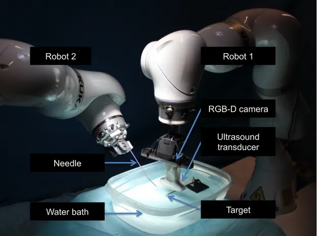
Robot 2 Robot 1
Needle
Ultrasound transducer
Water bath Target
RGB-D camera
Figure 2.5:The experimental setup is comprised by two KUKA iiwa, holding the needle and ultrasound transducer. A er calibra on of the base-to-base transforma on, visual servoing is performed to place the needle in the target, which is observed in the ultrasound image.
Figure 2.6:During needle placement the target ROI is con nuously co-registered between two sequen al images to compensate for its mo on. a) The red overlay displays the target in its ini al posi on and the blue overlay a er transla onal movement of±20 mm. b) The final registra on result is shown.
allow user interaction, trajectory planning, and real-time ultrasound visualization. The implementa-tion of the volume compounding, image registraimplementa-tion, and the processing of RGB-D point clouds uses parallelization on Graphics Processing Units (GPUs) for fast and efficient processing. The robots were controlled by a driver software using the KUKA SmartServo. Command messages were sent from the image processing computer via an OpenIGTLink connection. KUKA SmartServo can currently process commands at a rate of 50 Hz. The Euclidean positions of the robot were trans-ferred via the Fast Research Interface (FRI) [57],from the robot controller to the image processing computer at a rate of 250 Hz, which outperforms any commonly used clinical tracking system.
2.3.3 Target Tracking Accuracy Validation
The target tracking experiments included the two robots, where one operated the US transducer and the other one moved the phantom by a series of translations (±20mm). Over a time of 180 sec-onds, the transducer was robotically moved to follow the motion of the target. As shown in Fig.2.6, the registration results indicate reliable tracking, even considering drift over time. The overall trans-lational accuracy achieved for N=9 experiments is 0.6± 0.1 mm. The registration to the initial US image took around 500 ms. The spatial transformationUSTF1from the origin of the US image to
the transducer apex was determined by using the PLUS library [29] and a calibration phantom. The mean calibration error is 0.6± 0.2 mm. The mean calibration error of the needle tip to robot flange (NTTF2) is 0.6± 0.1 mm. Two sets of experiments, using two different types of phantoms were per-formed. The first phantom was a 260x190x135 mm box filled with water. The target was a 7 mm sphere which was submerged at around 80 mm below the surface. A water bath allowed easy ultra-sound imaging, but the impedance controller could not be used. The second phantom was made by filling a 240x150x120 mm box with 7 weight percent(wt%) 300 bloom pork gelatin as suggested in [58] and [59], to achieve acoustic tissue-mimicking properties. Different organic spherical objects with diameters between 7 and 17 mm were then submerged at different depths below the surface. Consistency between the two experiment was assessed by selecting the 7 mm sphere, placed around 80 mm below the surface as target. The user defined the desired target position, which is illustrated as red circle in in Fig. 2.7. The target positions were set to be on the surface of the sphere in all the experiments. During the tests with the gelatin phantom, all movements were executed using the impedance controller. A needle of 100 mm length was used, and the target area with 90x70x90 mm US volume was in non-stationary condition during insertion insertion, namely following a patient motion of±20mm. For each phantom needle insertion was performed at two different angles, 45◦ and 30◦with respect to the base plane of the box, and three different needle insertion velocities: 5 mm/s, 3 mm/s and 1 mm/s. The needle insertion was performed five times in each test, resulting in a total of 60 evaluated needle insertions. The robustness of the needle tracking was evaluated by placing a finger in the vicinity of –or even touching– the needle shaft (as shown in Fig. 2.4), to cre-ate additional signal and movement in the image. The needle tracking algorithm was evalucre-ated by recording the detected needle tip at different instances of time, as shown in Fig. 2.7. When the robot
needle tip needle shaft with
control points
target needle tip target
needle shaft with control points
Figure 2.7:Needle tracking while approaching a target, in which the yellow line represents the fi ed polynomial. The tracked p (blue) and the user-defined target (red) are visible.
Table 2.1:Average distances between needle p and targets for experiments with visual servoing. Each line summa-rizes five experiments. Two types of medium are used: Water - the targets were submerged in water; and Gel - the targets were submerged in ssue mimicking gela n phantom.
# Phantom Type Angle Avg. Errors
5mm/s [mm] Avg. Errors 3mm/s [mm] Avg. Errors 1mm/s [mm] 1 Water 30◦ 1.2± 0.1 1.3± 0.2 1.3± 0.1 2 Water 45◦ 1.1± 0.1 1.1± 0.1 1.0± 0.1 3 Gel 30◦ 0.87± 0.16 0.97± 0.15 0.82± 0.12 4 Gel 45◦ 0.9± 0.1 0.9± 0.2 0.8± 0.2
results are summarized in Tab. 2.1.
2.4 Discussion and Conclusion
A new concept for a framework capable of robotic needle placement under robotic US image guid-ance was presented. The needle placement was performed in a simplified setting using two different types of phantoms (water and gel). Targeting accuracy of the order of 1 mm was achieved when con-sidering a target point submerged in the above phantoms, irrespective of the needle orientation and speed. As shown in Tab.2.1 the water bath experiments had slightly higher needle tracking in-accuracies compared to the tissue-mimicking gel phantom. This is due to the mechanical vibration of the robot, which causes slight vibration of the needle itself in mechanically unconstrained
en-vironments. Experiments demonstrated that the dual-robot framework is able to successfully and robustly hit targets of 7 mm in diameter, as required in a wide range of clinical scenarios[32,60]. The obtained results supports the suitability of the proposed approach in a range of more realistic operating conditions, although more extensive evaluation, which take into account physically rep-resentative tissue (e.g. soft biological tissues), will be necessary. In a more realistic scenario, flexible needle deformation in soft tissue should be also considered, and the needle tracking function should be tested taking also in consideration the patient motion (respiration, cardiac motion, reflexive mo-tion, involuntary motion due to pain).
In comparison to systems with a needle guide or device attached to the US transducer [24], the use of a second robotic arm for the needle insertion retains the full versatility with respect to mean-ingful acoustic windows for imaging. Combining the advantages of previous approaches (namely the preoperative planning, the real-time tracking of the needle, and the trajectory update) the dual-robot system presented encompasses the state of the art in needle tracking techniques suitable for real-time operation, as well as in US-image compounding techniques for representing the targeted domain. All the techniques were efficiently implemented using GPU parallelization, allowing for the use of the full image resolutions at high frame rates.
The combination of planning, imaging, and action provides a proof of concept for developments toward dedicated clinical applications. In future, an automatic robot-to-robot calibration scheme can be implemented to further simplify the operative procedure. In this way, most of the techni-cal details that are related to the current developmental stage will be hidden in a later version of the user control interface, and usability by the clinical staff will be improved. In order to adapt size and optimal robot setup, it will be necessary to analyze the clinical environment and workflow of the
age of the proposed interventional framework. With the development of dedicated domain-specific robotic systems, purchase and maintenance of such manipulators come into the clinically and eco-nomically expedient range, in particular in the light of the current cost-effectiveness of relevant clin-ical applications such as RF ablation and cryoablation [61]. Future work will involve expanding the system to include anatomical target movement due to patient respiration and motion. This will in-clude tracking of the patient motion based on RGB-D cameras and target motion based on image registration. Evaluations of needle tracking in biological tissue also need to be taken into considera-tions. In future, more effort should be put in the understanding of the potential integration of the dual-robot system into the workflow of additional applications (e.g. RF ablation or cryoablation) by considering the corresponding clinical constraints.
3
Thyroid Ultrasound
3.1 Introduction
While US imaging techniques have become standard of care for many diagnostic and intervention applications, flexible, reliable and repeatable image acquisition is a crucial source of information
Figure 3.1:Anatomy of the Thyroid and Parathyroid Glands.
represented in US images is based on in-depth knowledge, training and experience. This leads to a strong operator dependence, and a possible variability of repeated measurements performed by one operator. In order to increase repeatability and reliability of measurements acquired intra-operatively, robotic ultrasound systems have been proposed [2,37,38,62,63], which assume that data acquired using robotic ultrasound is at least of the same quality as data acquired by an expert.
Longitudinal study of thyroids based on expert-operated and robotic sonography in healthy volunteers, is presented in this chapter. Cancerous Thyroid nodules are common clinical problem. Epidemiological studies have shown that with manual palpation the occurrence of thyroid nodules is approximately 5% in women and 1% in men living in iodine-sufficient parts of the world [64]. In contrast, with high-resolution US scanning thyroid nodules were detected in 19-67% of randomly selected individuals, with higher frequencies in women and in the elderly [65]. The occurrence of cancerous lesions involves the 5-15% of the thyroid nodules [66,67].
Figure 3.2:Anatomy of the Thyroid Glands in US images. a) Normal appearing glands, b) Complex most probably cys c thyroid nodule in the right thyroid lobe. c) Two large, hypoechoic nodules associated with poorly defined bor-ders, the le -sided nodules showing macro- and microcalcifica ons. d) An abnormal lymph node, round in shape with microcalcifica ons that are very consistent with thyroid metastasis[3].
In 2012 about 230,000 new cases of thyroid cancer were estimated among women and 70,000 among men, with an age-standardized (world population) rate of 6.1/10,000 women and
1.9/100,000 men [68]. Globally, it was estimated that the deaths from thyroid cancer were 27,000 in women and 13,000 in men, corresponding to mortality rates of approximately 0.6/100,000 women and 0.3/100,000 men. The incidence rates have been increasing over the last few decades [69,70]. If the incidence rate are maintained, thyroid cancer may become the fourth most common cancer by 2030 in the United States alone [71]. This increase is likely due to improved ascertainment, diagnosis and certification, and most probably it reflects over-diagnosis of small papillary carcinomas [67,69].
According to the American Thyroid Association guidelines, high-frequency US plays key role in the thyroid nodule evaluation [72]. US does not use ionizing radiation and is commonly used to evaluate lumps or nodules found during a routine physical or other imaging exam. Ultrasound examination of thyroid nodules can accurately determine if a nodule is solid or filled with fluid
(cys-that are hard to identify with physical examination [73]. Since US provides real-time images it can also be used to accurately guide a procedure, for example needle biopsies. In the case when it is hard to determine the properties of the nodule with palpation, fine needle aspiration (FNA) biopsy is performed under US guidance.
Non-palpable nodules detected on US have the same risk as of malignancy as palpable nodules with same size [3]. In the common practice, only nodules bigger than 1 cm are evaluated since they have greater potential to be clinically significant cancers. In some cases nodules smaller than 1 cm are evaluated with FNA biopsy due to suspicious finding in the US images, associated with lym-phadenopathy, a history of head and neck irradiation, or a history of head and neck cancer in one or more first-degree relatives. In some cases nodules smaller than 1 cm lack of these warning signs yet eventually cause morbidity and mortality.
Diagnostic thyroid US is performed in all patients with suspected thyroid nodule found either in computed tomography (CT) or magnetic resonance (MRI) or in thyroidal uptake on FDG-PET [72].
Benign thyroid nodules are followed with serial of US examinations six to eighteen months after initial FNA biopsy. If the nodule size remained less than 50% or less than 20% increase in at least two nodule dimensions from the initial US-based diagnosis, the next follow-up clinical examination or US scan can be longer, for example three to five years. In the opposite case and increase of the 2 mm in solid nodules, the US-guided FNA biopsy should be repeated [72].
US imaging is also used as follow up procedure for life long monitoring after thyroidectomy be-cause US is very sensitive way to find potential disease in the neck or to monitor the recovery time after thyroid surgery [72,74,75].
In the current clinical practice, the US imaging protocol includes measurements of both the thy-roid size, as well as the location and size of possible nodes. Standard screening procedure is shown in Figure 3.3. The examination is performed on each lobe individually. During the thyroid
exami-Thyroid glands Parahyroid glands Head Neck Ultrasound system Clinician Ultrasound transducer a) b)
Figure 3.3:The le and the right lobe of the thyroid (illustrated in a) are measured and inspected individually. Dur-ing the standard of care, the expert acquires 2D ultrasound images as seen in b). We hypothesized that the robo c ultrasound contributes in assis ng image acquisi on, and may lead to more reproducible results.
nation the clinician aligns the 2D ultrasound transducer with the transversal plane to measure the length of the thyroid lobe. Then the transducer is rotated to acquire an image a few degree off the sagittal plane, which allows measurement of width and depth of the thyroid lobe. After the mea-surement of size, the clinician sweeps the thyroid to monitor for suspicious tissue changes, such as nodes. Position within the node and size are recorded. Additionally, US imaging may allow basic tissue classification of nodes [72].
However, the potential of US imaging is limited due to its small field of view, low signal to noise ratio, and dependency of the operator. In the current clinical workflow, hand-held longitudinal US studies of the thyroid are cumbersome due to the fact that the diagnosis strongly depends on the image acquisition, image quality, and analysis performed by the radiologist. Previous literature have shown evidence of operator variability of US exams [76,77]. In case of detecting thyroid nod-ules which can be few millimeters of size, user dependency plays crucial role in making diagnostic decisions [72]. Clinicians base their decisions of treatment on this source of data. It is therefore paramount that the US images are acquired and analyzed by the same radiologist in order to have
The development of robotic ultrasound thyroid acquisition framework could not only improve the clinical outcome but could also provide solutions to hospitals and diagnosis when a primary ra-diologist who have made the initial acquisition is not available. Furthermore, robotic system which exerts constant force during US acquisitions could provide reliable and consistent imaging com-pared to hand-held images acquired from medical expert [78].
The use of robotics systems for thyroidectomy becomes standard for removing cancerous thyroid nodules [79] due to ease of use and the possibility to perform the procedure in minimally invasive manner. During these procedures also intraoperative US could be used to monitor in real time the location of vessels and avoid critical anatomical structures.
Previous technical work on preoperative and intraoperative robotic-guided US applications has been shown in the literature [2,25,37,38,80,81,82]. However none of the robotic US systems in-vestigated the impact of robotic system for US acquisitions of the thyroid, and furthermore none of the previously mentioned systems evaluated the US guided robotic systems beyond phantom and cadaver.
A novel platform for user-supervised robotic ultrasound acquisitions of the thyroid is presented in this chapter. The developed framework provides easy to use and safe solution, able to provide consistency between US images acquired in different time periods. The proposed solution incorpo-rates a lightweight robot and a RGB-D camera (i) to select a region of interest and plan the trajectory for ultrasound acquisition (ii) to perform user-monitored ultrasound acquisition and (iii) to per-form volume compounding of the acquired images. The system was verified by analyzing clinically relevant measures of the thyroid using robotic and expert-acquired ultrasound images.
Figure 3.4:The workflow is organized in three phases: the ini aliza on phase (red boxes), ultrasound volume acquisi-on (blue boxes), and the diagnosis and future ac acquisi-ons (green boxes)
3.2 Materials and Methods
3.2.1 System Overview and Workflow
The robotic ultrasound thyroid scan can be organized into three main components: (i) a one time initialization phase, which includes camera-to-robot calibration.(ii) The selection of region of inter-est is performed using the RGB-D camera 3D and color images, which are streamed in real time in the user interface. (iii) The Volume acquisition and processing allows systematic measurement of the organ, and the UI allows the medical expert to highlight suspicious nodules. Once all steps of the workflow are completed, the medical expert can analyze the acquired images and volumes. The platform workflow is shown in Figure 3.4
The camera–robot calibration is performed once the robots are positioned in the intervention room, before the patient arrives.
3.2.2 Initialization: camera-robot calibration
Figure 3.5:Chain of Transforma on of robo c thyroid US. The robo c system provides flange-to-base transforma on based on the known kinema cs. The camera-to-flange and US-to-flange transforma ons need to be calibrated once before deploying the system, while transforma ons describing the rela onship between the system and the pa ent are computed in real- me. Please refer to text for details.
pound the stack of 2D ultrasound slices into a volume, the relationship of each component must be calibrated.
To determine the extrinsic and intrinsic camera parameters, we have used the checkerboard method as described in [44].
The transformationsFTCare obtained through hand-eye calibration [43]. For the robot at two poses h and h + 1, the chain of transformations can be defined as:
Ch+1TC h
CTF =C TFFh+1TF
h, (3.1)
where the camera centers for pose h and h + 1 are obtained by tracking a checkerboard [44]. This procedure is repeated in order to increase the robustness of the calibrated transformation between the depth camera coordinate system and the robot flange. After acquiring a set of transformations, equation (3.1) needs to be solved forCTF,with the Levenberg-Marquardt non linear minimization method as described in [83]. The relationship between the US image (ultrasound transducer apex) and the robot flange(FTUS), allows precise tracking of each ultrasound slice and 3D image com-pounding. We use the known design of the transducer mount and perform pivot calibration [45], to initialize the standard ultrasound-to-tracking calibration. The Tool Center Points (TCP) are de-fined to be the ultrasound transducer apex. All the calibration steps are only performed once, as the camera and the transducer are rigidly mounted to the robot flange. This enables a flexible use of the system and fast setup in a clinical scenario.
face, to the operator for interactive selection by drawing a rectangle of the region of interest (ROI) containing the relevant area of the patient neck. The operator can then draw a line specifying the trajectory of the robot.
To acquire optimal US images of the selected ROI, the transducer needs to be placed perpendic-ular to the surface. In order to compute surface normals at the coordinates selected by the user, the specified trajectory needs to be projected onto the virtual 3D surface. We have performed this step by transforming the coordinates into the space of the dept camera’s coordinate system using the depth camera’s intrinsics and Inverse Brown-Conrady Distortion Model [84]. The neighboring 3D points are automatically detected using a kNN-based approach, and the surface normal at the user-specified points is computed [46]. An alternative approach is to automatically compute the trajectory points and normals based on 3D medical images, or earlier ultrasound acquisitions [37].
Robotic Ultrasound Acquisition and Trajectory Execution: The computed trajectory points in the depth camera coordinate space (PD) are then transferred to the coordinate space of the robot’s base (PB) through the following chain of transformations:
PB=BTFFTCCTDPD. (3.2)
Similarly the surface normals at each point are transferred between the aforementioned coordinate spaces,
NB=BTFFTCCTDND, (3.3)
where NBand NDbeing the surface normals in robot and depth camera coordinate spaces respec-tively.
Before executing the US acquisition, the operator applies sufficient US gel to achieve acoustic coupling, and is prompted to verify the planned trajectory. 2D US images are then recorded si-multaneously with the mechanical tracking data provided by the robotic system. After the data is
recorded, the US volume is compounded using a quadrilateral interpolation for a good trade-off between computational performance and image quality [47].
During the entire procedure, the impedance control mode is used for achieving compliant robot behavior. The motion model is based on virtual springs and dampers, whose tensions vary based on the measured and specified position of the TCP [48,57]:
τcmd=JT(kc(xcmd− xmsr) +D(dc) +Fdesired) +fdynamics(q, ˙q, ¨q) (3.4)
The resulting joint torque is computed by the transposed Jacobian (JT). The Cartesian stiffness parameter (kc), the Cartesian damping parameter (dc), the commanded (desired) Cartesian pose
(xcmd), and superposed Cartesian force/torque term (Fdesired), can be set individually in the Cartesian
space of the robot for every translation and rotational dimension during run-time. The dynamics model fdynamics(q, ˙q, ¨q) is predefined by the robot’s manufacturer. As the robot behavior during
impedance control is compliant, an external force or motion results in deviation between the set point and the actual (measured) poses of the robot. This results in deflection of the virtual springs, leading to a force in accordance with the Hooke’s law:
Fdesired=kc(xcmd− xmsr), (3.5)
where kcis the spring stiffness, and the deflection between the commanded and current(measured)
Cartesian pose is xcmd− xmsr. The compliant behavior allows us to implement set of control
strate-gies that allows the robot to exert constant force onto the patient’s surface, enabling a continuous contact between the US transducer and the patient surface. In combination with the previously
3.3 Experiments and Results
Four healthy volunteer were selected for an experimental evaluation of the proposed system. Each volunteer underwent multiple scan performed on each thyroid lobe in each dimension (transversal, lateral and anterior-posterior). For each lobe three acquisitions were taken from the robotic system and expert-operated hand-free acquisitions receptively, resulting in a total of 36 measurements for each volunteer. All the measurements were performed by the expert operator and were taken from different angles of 2D US images. The experiment aimed to validate the hypothesis that the mea-surements performed by an expert are at least as reliable when using robotic ultrasound volumes compared to expert-acquired ultrasound images. For this purpose, images acquired with the robotic framework were compared to hand-held US acquisitions performed by a medical expert.
3.3.1 Experimental Setup
For Ultrasound image acquisition we use Ultrasonix® SonixTableTMsystem together with a linear transducer L14-5/38 to obtain the ultrasound images (Analogic, Peabody, MA, USA). The acqui-sition rate, frequency, depth and gain are set to 30 Hz, 10 MHz, 40 mm, and to 55%, respectively. Using the Ultrasonix® API, the images are transferred via Ethernet to the image processing com-puter.
The RGB-D camera is an Intel® RealSenseTMSR300 3D camera, which provides RGB data at
1920× 1080 pixels at 30 frames per second and depth images at a resolution of 640 × 480 pixels
at 60 frames per second. The observable depth range is 0.2 to 1.2 meters. To mount the ultrasound transducer and RGB-D camera to the robots, custom adapter was designed and 3D-printed.
For experiments we use the KUKA LBR Intelligent Industrial Work Assistant (iiwa) 7 R800 robots (KUKA Roboter GmbH, Augsburg, Germany). The system is comprised of a 7 joint arm with corresponding control units and consequently enables one redundant degree of freedom (7

![Figure 2.2: The workflow is organized in three phases: the ini aliza on phase (red boxes), ultrasound volume acquisi- acquisi-on (blue boxes), and the US-guided needle inser acquisi-on (green boxes)[2].](https://thumb-eu.123doks.com/thumbv2/123dokorg/2927836.18831/21.918.145.776.140.281/figure-workflow-organized-ultrasound-acquisi-acquisi-guided-acquisi.webp)