1 UNIVERSITÀ DI PISA
Dipartimento di Oncologia, dei Trapianti e delle Nuove Tecnologie in Medicina Corso di Dottorato in Tecnologie per la Salute:
Valutazione e Gestione delle Innovazioni nel Settore Biomedicale X9 Ciclo
Ph.D Thesis
Image guided robotic assistance for the diagnosis and treatment
of tumor
Cinzia Freschi
Submitted to the University of Pisa in partial fulfillment of the requirements for the degree of Doctor of Philosophy
Tutor:
Prof. Andrea Pietrabissa Prof. Mauro Ferrari Dr. Vincenzo Ferrari
1
Table of contents
Table of contents ... 1 Abstract ... 3 Part I – Introduction ... 7 1 Context of thesis ... 71.1 Robotic surgical assistance ... 9
1.2 Image Guidance ... 11
1.3 Contribution of the thesis ... 14
1.3.1 EndoCAS Navigator ... 15
1.3.2 Structure of the thesis ... 19
Part II Work Description ... 20
2 The da Vinci robot from an engineering point of view ... 20
3 Integration of a Robot in a image guided system ... 38
3.1 Introduction ... 38
3.2 Robot Calibration... 40
4 Integration of ultrasound imaging in an image guided system ... 47
4.1 Ultrasound Calibration... 49
4.2 Implemented method ... 58
5 Applications... 62
5.1 Ultrasound guided robotic biopsy ... 62
5.1.1 Introduction ... 62
5.1.2 Methods and Instruments ... 65
5.1.3 Results ... 72
5.2 A Mixed Reality Navigation Guidance for HIFU treatment ... 74
5.2.1 Methods and Instruments ... 77
2 Part III Conclusion ... 88 References ... 91
3
Abstract
The aim of this thesis is to demonstrate the feasibility and the potentiality of introduction of robotics and image guidance in the overall oncologic workflow, from the diagnosis to the treatment phase.
The popularity of robotics in the operating room has grown in recent years. Currently the most popular systems is the da Vinci telemanipulator (Intuitive Surgical), it is based on a master-slave control, for minimally invasive surgery and it is used in several surgical fields such us urology, general, gynecology, cardiothoracic. An accurate study of this system, from a technological field of view, has been conducted addressing all drawbacks and advantages of this system. The da Vinci System creates an immersive operating environment for the surgeon by providing both high quality stereo visualization and a human-machine interface that directly connects the surgeon‘s hands to the motion of the surgical tool tips inside the patient‘s body. It has undoubted advantages for the surgeon work and for the patient health, at least for some interventions, while its very high costs leaves many doubts on its price benefit ratio.
In the robotic surgery field many researchers are working on the optimization and miniaturization robots mechanic, while others are trying to obtain smart functionalities to realize robotic systems, that, ―knowing‖ the patient anatomy from radiological images, can assists the surgeon in an active way.
Regarding the second point, image guided systems can be useful to plan and to control medical robots motion and to provide the surgeon pre-operative and intra-operative images with augmented reality visualization to enhance his/her perceptual capacities and, as a consequence, to improve the quality of treatments.
To demonstrate this thesis some prototypes has been designed, implemented and tested.
4 The development of image guided medical devices, comprehensive of augmented reality, virtual navigation and robotic surgical features, requires to address several problems. The first ones are the choosing of the robotic platform and of the image source to employ.
An industrial anthropomorphic arm has been used as testing platform. The idea of integrating industrial robot components in the clinical workflow has been supported by the da Vinci technical analysis.
The algorithms and methods developed, regarding in particular robot calibration, based on literature theories and on an easily integration in the clinical scenario, can be adapted to each anthropomorphic arm. In this way this work can be integrated with light-weight robots, for industrial or clinical use, able to work in close contact to humans, which will become numerous in the early future.
Regarding the medical image source, it has been decided to work with ultrasound imaging. Two-dimensional ultrasound imaging is widely used in clinical practice because is not dangerous for the patient, inexpensive, compact and it is a highly flexible imaging that allows users to study many anatomic structures. It is routinely used for diagnosis and as guidance in percutaneous treatments. However the use of 2D ultrasound imaging presents some disadvantages that require great ability of the user: it requires that the clinician mentally integrates many images to reconstruct a complete idea of the anatomy in 3D. Furthermore the freehand control of the probe make it difficult to individuate anatomic positions and orientations and probe repositioning to reach a particular location. To overcome these problems it has been developed an image guided system that fuse 2D US real time images with routinely CT or MRI 3D images, previously acquired from the patient, to enhance clinician orientation and probe guidance.
5 The implemented algorithms for robot calibration and US image guidance has been used to realize two applications responding to specific clinical needs. The first one to speed up the execution of routinely and very recurrently procedures like percutaneous biopsy or ablation. The second one to improve a new completely non invasive type of treatment for solid tumors, the HIFU (High Intensity Focused Ultrasound).
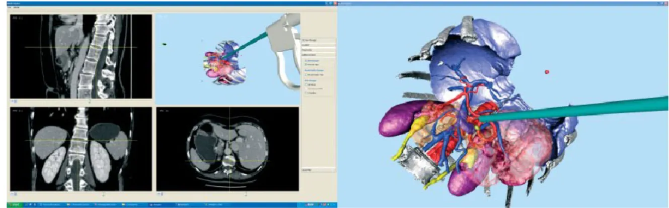
An ultrasound guided robotic system has been developed to assist the clinician to execute complicated biopsies, or percutaneous ablations, in particular for deep abdominal organs. It was developed an integrated system that provides the clinician two types of assistance: a mixed reality visualization allows accurate and easy planning of needle trajectory and target reaching verification; the robot arm equipped with a six-degree-of-freedom force sensor allows the precise positioning of the needle holder and allows the clinician to adjust, by means of a cooperative control, the planned trajectory to overcome needle deflection and target motion.
The second application consists in an augmented reality navigation system for HIFU treatment. HIFU represents a completely non invasive method for treatment of solid tumors, hemostasis and other vascular features in human tissues. The technology for HIFU treatments is still evolving and the systems available on the market have some limitations and drawbacks. A disadvantage resulting from our experience with the machinery available in our hospital (JC200 therapeutic system Haifu (HIFU) by Tech Co., Ltd, Chongqing), which is similar to other analogous machines, is the long time required to perform the procedure due to the difficulty to find the target, using the remote motion of an ultrasound probe under the patient. This problem has been addressed developing an augmented reality navigation system to enhance US guidance during HIFU treatments allowing an easy target localization. The system was implemented using an additional free hand ultrasound
6 probe coupled with a localizer and CT fused imaging. It offers a simple and an economic solution to an easy HIFU target localization.
This thesis demonstrates the utility and usability of robots for diagnosis and treatment of the tumor, in particular the combination of automatic positioning and cooperative control allows the surgeon and the robot to work in synergy. Further the work demonstrates the feasibility and the potentiality of the use of a mixed reality navigation system to facilitate the target localization and consequently to reduce the times of sittings, to increase the number of possible diagnosis/treatments and to decrease the risk of potential errors. The proposed solutions for the integration of robotics and image guidance in the overall oncologic workflow, take into account current available technologies, traditional clinical procedures and cost minimization.
7
Part I – Introduction
1 Context of thesis
Computer science and technology have strongly transformed the clinical practice over the last decades. This technically oriented evolution was parallel to evolutions of medicine[1]. Diagnostic and therapeutic procedures tend to be less invasive for the patient aiming at reducing pain, post-operative complications, and recovery time. Minimal invasiveness results in smaller targets reached through narrow access (natural or not) with no direct sensing (vision, touch) and limited degrees of freedom imposed by the access ports. Main clinical applications are in endoscopic surgery where instruments and optics are introduced in the patient‘s body through small incisions. it imposes significant ergonomic restriction on the operating surgeon practicing this technique [2] as the surgeon has to overcome the following perceptual-motor difficulties:
• Two dimensional (2D) vision from a conventional monitor (reduces perception of depth);
• A disturbed eye hand-target axis (decreases ergonomics and dexterity);
• Instrument guidance (requires ambidextrous manual activity); • Long rigid instruments used in laparoscopic surgery ( magnify the surgeon's natural hand tremor);
• The instruments have only five degrees of freedom (DOF): four for positioning of the tip and one for the actuation ( these limit the surgeon's natural range of motion, decreasing dexterity);
• Fixed abdominal entry points ( limit the workspace reachable with the instruments tip);
8 • Instrument tip and handle move in opposite direction ( a technical drawback known as the fulcrum effect and which decreases the motor-perception capability);
• Camera instability ( contributes to surgeon fatigue); • Limited tactile feedback ( reduces dexterity).
Further than surgery, all minimally invasive diagnostic or therapeutic procedures require particular ability of the physician.
To overcome to these limitations have been adopted new computer based technologies. Computer assisted surgery (CAS), Computer Assisted Medical Interventions (CAMI), Computer Integrated Surgery and Therapy (CIST) , Image Guided Surgery (IGS), Augmented Reality in Medicine and Surgery, Surgical Navigation, Medical Robotics for Surgery, and others, are different acronyms or expressions that represent the same concept:‖Computer assisted surgery aims at providing tools that allow the clinician to use multi-modality data in a rational and quantitative way in order to plan, to simulate and to accurately and safely execute mini-invasive medical interventions‖[1]. Medical interventions include both diagnostic and therapeutic actions. Therapy may involve surgery, radiotherapy, local injection of drugs, interventional radiology, etc.
Image guidance, in general, can reduce the inherent invasiveness of surgery and improve localization and targeting by intraoperative imaging using fluoroscopy, ultrasound, magnetic resonance imaging, etc. Alternatively, by means of localization systems, intraoperative image guidance can be based on previously acquired images using reference frames attached to the patient (frame based stereotaxy) or images which are registered to the patient (frameless stereotaxy). In the latter case, computers can pilot the operator through 3D coordinates and thus fulfill the need for enhanced visibility during interventional radiology and minimally invasive surgical procedures.
9 Furthermore, the fusion of pre-operative and intra-operative data (consisting in medical images and sensors data) in a multimodal representation of the surgical scenario, coherent with the real one, allows the use of programmable (and sometimes intelligent) machines, such as robots and mechatronic tools, that automatically or semi-automatically perform single steps or whole surgical procedures.
An Computer Assisted Surgery (CAS) system then provide two main types of assistance exist: image guidance and robotic aids. In the following paragraph a detailed description of this features is provided.
1.1 Robotic surgical assistance
Robots were first utilized in surgery in the mid 1980s. They used to assist surgeons during neurosurgical and orthopedic procedures, these early surgical devices were designed to aid with predefined tasks that required a high degree of accuracy and reproducibility.
Automation is not a primary goal of medical robotics where the interaction with the clinical operator has to be considered with a very special attention. Indeed, often medical robots are not intended to replace the operator but rather to assist him/her where his/her capabilities are limited. Medical robots may be classified in many ways: by manipulator design (e.g., type of kinematics, type of actuation, …); by automation level (e.g., preprogrammed control versus teleoperated control versus constrained cooperative control), by targeted anatomy or technique (e.g., cardiac, intravascular, percutaneous, laparoscopic, microsurgical); intended operating environment [e.g., in-scanner, conventional operating room (OR)], etc[2]. In this thesis it was chosen to classify robots in base of level of autonomy. Surgical robots assist surgeons for the moving of surgical instruments, sensors, or other devices useful to threat the patient. The type and the level of assistance offered by robots can be classified as follow:
10 Preprogrammed, semi autonomous motion: The desired behavior of the robot‘s tools is specified interactively by the surgeon, usually based on medical images. The computer fills in the details and obtains the surgeon‘s concurrence before the robot is moved. Examples include the selection of needle target and insertion points for percutaneous therapy and tool cutter paths for orthopedic bone machining. An example is the Neuromate system (Integrated Surgical systems, Sacramento, CA) designed to facilitate stereotactic neurosurgical procedures
Teleoperated control: The surgeon specifies the desired motions directly through a separate human interface device and the robot moves immediately its arms as required. Examples include common telesurgery system such as the da Vinci. Although physical master manipulators are the most common input devices, other human interface are also used, i.e voice control (Aesop by Intuitive Surgical, Inc).
Cooperative control: The surgeon can grasps tool held by the robot or a control handle on the robot‘s end effector. Often force sensors sense the direction that the surgeon wishes to impose on the tool and the controller moves the robot as desired. Early experiences showed that the surgeons found this form of control to be very convenient and natural for surgical tasks.
These control modes are not mutually exclusive and are frequently mixed. For example, the Robodoc system (Integrated Surgical Systems, Inc. of Sacramento, California), a robot for orthopedic surgery, uses cooperative control to position the robot close the patient‘s femur or knee and then preprogrammed motions for bone machining are executed. Similarly the LARS robot [3] used cooperative and teleoperated control modes always in the field of orthopedic surgery. The popularity of robotics in the operating room has grown in recent years. Currently the most popular systems is the da Vinci telemanipulator (Intuitive Surgical) used in several surgical fields such
11 us urology, general, gynecological cardiothoracic. This technology has undoubted advantages for the surgeon but it is very bulky and expensive. Despite the large number of reported series and randomized controlled clinical trials the evidence of benefit from use of this very expensive technology remains uncertain. Even if exist many clinical studies and also some economic evaluation to try to quantify robot efficacy in respect to its cost, until now no detailed studies describing it from a technological point of view are done. In the thesis an accurate review of the da Vinci from an engineering point of view was performed and it is shown in the next part.
1.2 Image Guidance
In the field of minimal invasive image guided surgery, images from modalities like CT, MRI and ultrasound are used to plan a surgical procedure, to guide the surgeon intraoperatively to move surgical instruments a to monitor the procedure and to control and evaluate the results. The first computer-assisted systems that tried to bridge the gap between preoperative diagnostic image data (CT, MRI) and the patient in the operating room were used in the neurological field and were frame-based stereotactic systems [4-6]. These systems used specially designed frames, attached to the patient‘s head during preoperative image acquisition and surgery, in order to register the images to the patient. Though highly accurate these systems had several disadvantages (invasive, cumbersome and time-consuming) and were gradually replaced by frame-less stereotactic systems [6-7] as improvement of the technology. The actual image guided systems differ in the way they integrate preoperative image data with physical space (i.e. patient registration), the kind of tracking technology they use to follow the surgical tools that are used (e.g. optical, magnetic, ultrasonic or mechanical) and in the way the image information is presented to the surgeon. A short overview of the major components of an image guided system is given.
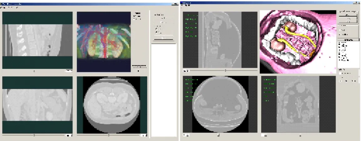
12 3D model generation and Visualization: The first step is the acquisition of preoperative medical images of the target anatomy. Given a volume dataset, usually from magnetic resonance imaging (MRI) or computed tomography (CT), it can be necessary either to reconstruct a 3D digital model of the information contained (to be used in further processing), or to render images representing the same information. There are two basic classes of volume visualization algorithms in use today: Surface– based Rendering techniques and Direct Volume Rendering techniques (Fig. 1-1). In volume rendering, images are created directly from the volume data, and no intermediate geometry is extracted. The key idea of surface-based rendering methods is to extract intermediate surface descriptions (by means of a segmentation process) of the relevant objects from the volume data, which are in general produced and stored as triangle meshes, then used for rendering. The general approach used to perform the surface extraction after dataset segmentation is called ―marching cube‖. An important point is that the intermediate result (the 3D surface-based digital model) can be used for many other applications, such as the computation of volumes or masses, the creation of physical copies, an easier integration with physical models (e.g. for the representation of deformable materials), etc. The importance of surface-based techniques is thus not restricted to pure visualization.
13 Localization and Calibration of surgical tools. Intra-operatively, a localizer system (usually optical or electromagnetic) is used to allow the localization and tracking of position and orientation of tools (surgical instruments, therapeutic or imaging devices and robotic system). Localization of tools requires their sensorization and calibration. Sensors have to be designed and positioned in order to guaranty their functionality and safety. Calibration procedure is required to determine the relation between the sensor and the tool. Often image guided systems integrate a 3D model of each tool to show its real time position. Calibration allows to calculate where the tool 3D model have to be positioned in respect to the position and the orientation read from the sensor.
Patient Registration. Mixing virtual pre-operative information (extracted from the medical dataset) with real intraoperative information (consisting in the patient himself), requires the alignment of the virtual anatomy to the real one. This process, called registration, requires to determine the geometrical transformation of correspondent points taken in two different reference frames and in two different time instants. In fact, pre-operative information are given in the reference frame of the radiological device and are acquired some days before the intervention, while the intra-operative information are given in the reference frame of surgical room (defined by means of a tracking system) and are acquired during the intervention the patient's anatomy to the 3D patient model obtained preoperatively.
Image guided systems based on preoperative images have a serious disadvantage. During the surgical procedure, the anatomy move and deform so that images acquired before surgery (i.e. the map) will not correspond to the patient any more.
The anatomy shift problem [8-9] can only be solved adequately by integrating intraoperative imaging with navigation technology. A common way of doing this is to transport the patient in and out of an
14 intraoperative CT [10-12] or MRI [13-15] scanner in order to update the images (i.e. the map) during surgery (the scanners can also be moved over the patient). This has obvious logistic drawbacks that limit the practical number of 3D scans acquired during surgery. Interventional MRI systems [16-18] solve these problems by the surgeon have to operate inside the magnet. Further, these systems require high investments, high running costs, and a special operating room broader as well as surgical equipment. Intraoperative ultrasound [19-20] is a flexible, relatively low costs alternative that has gained a increasing acceptance as a result of improved image quality and integration with navigation technology. However, 2D a 3D ultrasound acquisition covers only a limited part of the surgical field making it hard to get an overview of surrounding anatomy, which frequently is needed. In addition, high quality preoperative CT and MRI data are often generated anyway for diagnostic and planning purposes and additional functional MRI will often be beneficial, both for preoperative planning and guidance. Hence in order to perform safe and accurate surgery it will be beneficial to use intraoperative ultrasound in combination with preoperative MRI / CT. There are different strategies for the combined use of both pre and intraoperative data. Indirect use of ultrasound to track the anatomical changes that occur, apply these changes to elastically modify preoperative data and navigate according to manipulated MRI/CT volumes have been suggested.
In the present work ultrasound data are used as maps for intraoperative navigation and preoperative data are used for procedure planning, and to provide an overview of the anatomy during image guided interventions.
1.3 Contribution of the thesis
The work has been done at the EndoCAS Center, Cisanello Hospital, Pisa (Italy). One of the main activity of the center is the development of high-tech systems designed to overcome the current limits of surgery
15 and radiology. EndoCAS carry out simultaneously basic and applied research. Starting from real clinical problems and defining the technical-functional specifications for an "ideal" system that can solve them, the center faces the basic research issues to find the solution necessary to develop the system. In the opposite direction, the results of basic research at the state of the art are pushed into the design of new Computer assisted systems in order to improve the current surgical procedures, to reduce their invasiveness, or to allow new interventional procedures. It was developed a generic platform for computer assisted surgery presented in the next paragraph. The solutions developed in this thesis were integrated and used in the EndoCAS Navigator platform. In other cases EndoCAS Navigator was used as testing environment because, integrating several aspects of CAS into a modular open architecture, allows rapid developing of new functionalities and new applications [21-23]. The dissertation often refers to EndoCAS Navigator platform and its components.
1.3.1 EndoCAS Navigator
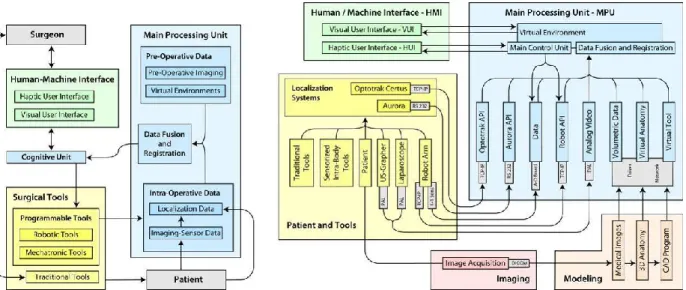
From a functional point of view, the specifics of the platform are illustrated in Fig. 1-2(left).
Fig. 1-2 The functional scheme of the computer assistance system (left) and scheme of the integrated CAS system, showing the hardware and software components, the
16 The scheme highlights the communication between the main functional modules of the system and the interaction between system, surgeon and patient. The platform consists of three main functional modules: the surgical tools, the main processing unit, and the human/machine interface. The surgical tools module comprises the instruments used to perform the interventions. Tools are classified into traditional tools and programmable tools. Tools commonly used in surgical practice and managed by surgeon in a traditional way fall in the first category. These tools, used for imaging (laparoscopes, ultrasound probes, etc.) and intervention (scalpel, forceps, cauterizer, drill, biopsy needle, etc.), are passive, for what concerns movement control, and work under direct manual control of the surgeon. In contrast, programmable tools category encompasses active, intelligent tools (such as mechatronic and robotic tools), provided with sensors and programmable actuation capabilities. The main processing unit (MPU) processes and integrates preoperative data with intraoperative data concerning the surgical environment and the internal status of the programmable tools. Integrated data (provided by the Data Fusion and Registration module) are processed by the Cognitive Unit and returned to the surgeon in form of sensorial enhancement by means of the Human/Machine Interface (HMI). The HMI is composed by two modules that can function independently: the Visual User Interface (VUI) and the Haptic User Interface (HUI). The status of both interfaces is updated in real-time. The surgeon interacts with the programmable tools through the HMI. The Cognitive Unit, integrating commands given on the HMI with the information provided by the MPU, provides for visual safe guidance and monitoring dangerous situations that may occur during navigation (i.e. contact, proximity etc.) and acts as an intelligent and active filter to the programmable tools commands given by the surgeon, inhibiting or re-interpreting the most critical ones. The synergy between system and surgeon is achieved by means of the Cognitive Unit which by implementing a closed loop between surgeon‘s commands, programmable tools and MPU, enhances overall performance. EndoCAS
17 Navigator is based on the described functional approach, and enables the selection of the appropriate components for specific applications. The system can be used for preoperative visualization, diagnosis and planning, intra-operative passive and active guidance. Furthermore, the system integrates components such that it is capable of adaptation for a variety of application domains. The integrated system is illustrated in Fig. 1-2 (right), which highlights the hardware and software components and their intercommunication. The availability of virtual models of all relevant elements in the surgical scene is a prerequisite for the construction of the Virtual Environment. Medical images of the patient are acquired preoperatively (Image Acquisition). Surface models are created by a modeling process in order to build realistic geometrical virtual models of the anatomical organs and structures (Virtual Anatomy) involved in the intended operation. Virtual models of the surgical tools (Virtual Tools) and of all devices that will interact with the patient are generated using computer aided design programs. During the intervention, in order to place the elements correctly in the surgical scene, realtime information about their spatial position are provided by the localizer. The different reference frames, in which spatial coordinates are described, need to be co-registered and aligned with the virtual representations of the anatomies (registration).The geometrical description of the surgical scene is enhanced by information derived from intraoperative imaging devices (Laparoscope, US) and data collected by different types of sensors. All these data sets are integrated into the virtual environment by a Data Fusion process. Both optical (Optotrak Certus®, Northern Digital Inc.) and electromagnetic (NDI Aurora®, Northern Digital Inc.) localization devices have been integrated in the platform respectively for external-body and internal-body localization. A software module, on the top of API of the localizers, that provides a unique interface to configuration and management functions, and allows the use of both in the same application, has been developed and integrated. The module also implements methods for calibration of localization sensors with respect to tools shape and
18 functionalities. Specific procedures have been implemented for automatic dynamic calibration of sensors mounted on the surgical tools, and for manual calibration based on the digitalization of reference points on the tools. Other calibration procedures concern the robot-localizer calibration, and intra-operative imaging devices calibration (such us laparoscopic camera and US probe). The control loop implemented in the core of the MPU (Cognitive Unit) monitors the virtual environment and is responsible for determining the feedback actions associated to the state of the virtual environment. Virtual environments are created integrating in the same view both extracted surfaces and original volumetric datasets (orthogonal slices). The visualization module (developed using the open source framework OpenSG [www.opensg.org]) allows the visualization of virtual environments, modification of the virtual scene settings (transparency, slice position, organs to be visualized), virtual navigation inside the patient by moving the viewpoint by means of a 6D mouse, and perception of stereoscopic images by means of a Head Mounted Display (HMD). Also mixed-reality functionalities have been integrated. The module implements two main functions: the video acquisition and streaming function that manages the image capture from a generic local or remote video source, and the mixing function that synthesizes the hybrid image using video frames and virtual 3D models.
19 In the platform has been integrated an industrial robot to provide active surgical assistance and accurate positioning during intervention (chapter 3).
1.3.2 Structure of the thesis
The following part of the thesis describes the operative work performed. In the chapter 2 the review of the daVinci from an engineering point of view is presented. In the chapters 3 and 4 are addressed the two main issues the integration of a robot (chapter 3) and of an ultrasound imaging system (chapter 4) in a image guided system. In the chapter 5 are presented two application implemented an ultrasound robotic guided biopsy and an mixed reality navigation system for HIFU treatment. Finally in Part III the conclusions are drawn.
20
Part II Work Description
2 The da Vinci robot from an engineering point
of view
During the thesis it has been made an accurate review of the literature regarding da Vinci surgical tele-manipulator from an engineering technical view point [24]. The description done in the following pages allows to understand what are the technical aspects that determine robot advantages and motivations of its (few) drawbacks.
The review is based on publications identified in a detailed literature search on ISI Web and PubMed databases and on scrutiny of design details described in patents submitted by Intuitive Surgical Inc. in addition to other relevant papers not indexed on ISI Web or in PubMed but identified from the indexed papers. Additionally, where appropriate in order to understand or clarify some aspects of the robot some key exercises have been performed directly with the da Vinci, available at our institution in Pisa.
Da Vinci System Description
The da Vinci is a teleoperating robotic system based on a master-slave control. It consists of two major subsystems. One subsystem is the surgeon‘s console, housing the image display, the surgeon‘s master interfaces, the surgeon‘s user interface and the electronic controller. The second subsystem is the patient side cart, consisting of the slave manipulators: fully sterilizable surgical instruments and tool robotic arms. Additionally, the sterilizable camera is attached to third robotic arm and is mechanically identical to the others, except for a dedicated camera attachment.
The daVinci System creates an immersive operating environment for the surgeon by providing both high quality stereo visualization and a man-machine interface that directly connects the surgeon‘s hands to
21 the motion of the surgical tool tips inside the patient‘s body. The surgeon visualizes the stereoscopic images by a 3D display located above the hands, restoring hand-eye coordination and providing an intuitive correspondence with manipulations. Furthermore, the controller transforms the spatial motion of the instruments into the camera frame of reference, so that the surgeon feels as if his hands are inside the patient‘s body. Lastly, the da Vinci system restores the degrees of freedom lost in conventional laparoscopy by placing a 3 DOF wrist inside the patient enabling natural wrist pronation/supination, and providing a total of seven DOF for control of the instrument tip (3 orientation, 3 translation and grip). The system also uses its control system to filter out surgeon tremor, making the instrument tips steadier compared to the unassisted hand. Also, the system allows for variable motion scaling from each master (moved by surgeon‘s hands) to each slave.
Design description and movement of surgical instruments
From a functional viewpoint, the system offers two features: surgical scenario visualization, by means of the laparoscope connected to the 3D display and transformations of the surgeon‘s hands movements to the movements of the surgical instruments. Since the first version (in 2000 the robot received FDA approval) the system has been modified, however the master console and the slave robot mechanisms have essentially remained the same (the changes made relate only to their mechanical design).
22
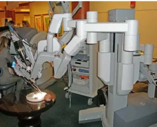
Patient side cart
Fig. 2-1 Da Vinci patient side chart.
The cart (Fig. 2-1) consists of a moveable base with 4 mounted arms: one for endoscope/camera placement and three for instrument manipulation. All four arms are attached to a central column through vertical prismatic joints. Each of the arms has a set of non-actuated joints (adjusted manually by releasing the associated brakes) that position a distal set of active joints (controlled by the surgeon through the master surgical tools – these can also be adjusted manually). The active joints are the only ones that move the end-effectors during surgery, i.e., involved in the performance of the manipulator. All the arms have the same kinematic structure: six non-actuated joints, six active joints and several passive joints (Fig. 2-2) [25].
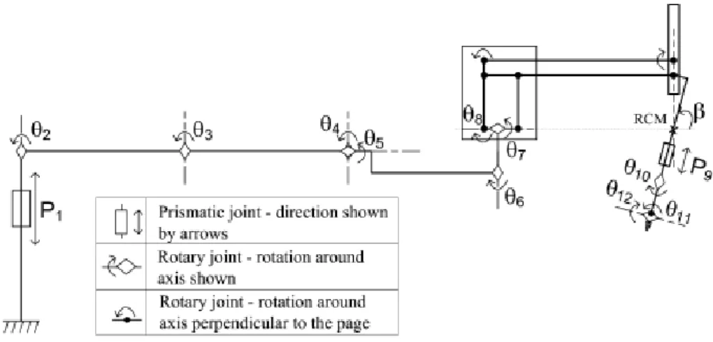
23 Fig. 2-2 Kinematic configuration of each da Vinci arm consisting of a mechanical chain of links and joints. The symbol , on the left, represents the floor of the room where
the cart is positioned. Prismatic joints, indicated by Pi, represent links that can translate in respect to the previous one. Rotary joints, indicated with Ɵi, represent links that can rotate in respect to the previous one. The rotary angle indicated with β
represents the remote center of motion (RCM) fixed with the entry point on patient skin.
The last two joints, θ11, θ12, are related to the EndowristTM instrument tip mechanism (Fig. 2-3), which permit the increased DOF with respect to traditional laparoscopy [26]. The roll around the instrument shaft is represented by θ10. These DOFs are integrated in the da Vinci sterilizable surgical instruments, which can integrate one additional DOF: opening/closing, in case of scissors or grippers.
Fig. 2-3 Detail of a microsurgical EndowristTM instrument: round tip scissors. The da Vinci surgical instruments are mounted on rail that allows its translation (insertion/extraction into and from the patient‘s body cavity): P9.
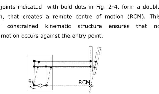
24 The passive joints indicated with bold dots in Fig. 2-4, form a double parallelogram, that creates a remote centre of motion (RCM). This mechanically constrained kinematic structure ensures that no translational motion occurs against the entry point.
Fig. 2-4 Double parallelogram forming the RCM . Actuation of θ8 joint moves the instrument shaft around RCM.
The robot moves the pitch of the instrument‘s shaft by moving the entire arm supporting the rail actuating the parallelogram (θ8). Θ7 moves the jaws of the instrument‘s shaft rotating the entire remote centre of motion mechanism. The other joints (passive or servo assisted) are manually moved at the beginning of the intervention to adjust the position of the arms and the fulcrum point. During the intervention they are usually locked.
Surgeon’s console
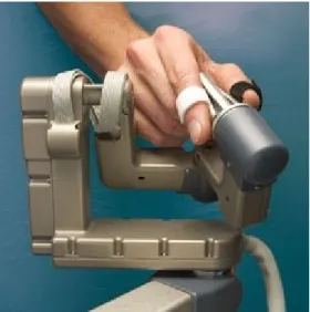
Fig. 2-5 The surgeon at the console and the patient side cart (on the background). The surgeon controls the slave seated on a stool at the computer console which is positioned remotely from the patient (Fig. 2-5). The console serves as the interface between the surgeon and surgical robot.
25 The surgeon views the operation through binoculars housed in the console‘s hood. An infrared beam deactivates the robotic tower whenever the surgeon removes his eyes from the binoculars. The surgeon‘s arms are supported by a padded armrest. The surgeon can also control motion scaling between movements of the masters and the translated motions of the robotic surgical instruments. The surgeon‘s console includes two master interfaces, consisting in two kinematics chains movable by the surgeon‘s hands, which control the two active slave manipulators. The same master interfaces are used together to control camera positioning. This function is activated by a foot pedal. Fig. 2-6 shows the da Vinci handle. The thumb and index finger of each hand are placed in a virtual gripper interface, attached to each handle of the distal part of the master interface, by means of adjustable Velcro straps.
Fig. 2-6 The da Vinci handle used to remotely move the instruments tip.
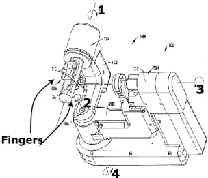
Each handle allows rotations around the three Cartesian axes of a frame fixed on the handle itself, by means of sensors. Each handle allows rotations around the three Cartesian axes of a frame fixed on the handle itself, by means of sensors. The handle has a redundant joint (joint number four) as shown in Fig. 2-7.
26 Fig. 2-7 Design details of the da Vinci handle (Patent US6364888B1 ). The virtual gripper interface, moved by the fingers, allows rotation of the four sensorized joints
shown in the figure.
The 4th axis (see axis 4 in the Fig. 2-7 ) was introduced to permit angles multiples of 180° [Patent US6364888B1].
The handle is attached to the proximal part of the master interface as shown in Fig. 2-8.
Fig. 2-8 The da Vinci master interface (Patent US6364888B1) with the handle in the yellow circle.
The proximal part of the master interface has three joint that allow the rotations around axes A, B and C (Fig. 2-9).
Fingers
1
2 3
27 Fig. 2-9 The three rotational joints (A, B and C) in the distal part of the master
interface.
Mapping between movements of the master interfaces and the slaves manipulators
The controller transforms the spatial motion of the master interfaces into the camera frame of reference, so that the surgeon feels as if his hands are inside the patient‘s body. The registration, or alignment, of the surgeon‘s hand movements to the motion of the surgical instrument tips is both visual and spatial. The system projects the image of the surgical site above the surgeon‘s hands (via mirrored overlay optics), restoring hand-eye coordination and providing a natural correspondence in motions. Furthermore, the controller transforms the spatial motion of the instruments into the frame of reference of the camera, such that the surgeon feels as if his hands are inside the patient‘s body [27], see Fig. 2-10.
28 Fig. 2-10 Relation between the eyes of the surgeon in respect to his/her fingers (A) and
between the endoscope and the instrument tip (B) (Patent US6364888B1).
The angles between the virtual gripper interface frame, in respect to the display frame, are repeated on the slave, between the end effector frame with respect to the camera frame, by the controller. The end effector frame origin is positioned on the fulcrum of the real surgical gripper, as the virtual gripper interface frame origin is positioned on its fulcrum itself. In this way each rotation around the virtual gripper interface fulcrum is mapped as the same rotation around the real gripper fulcrum.
Relative translation between the virtual gripper interface frame, with respect to the display frame, are repeated by the controller on the slave, between the end effector frame with respect to the camera frame. In this way, if the surgeon using motion scaling 1:1 moves by 1 cm the virtual gripper interface to the left; with respect to the display the surgical instrument gripper fulcrum moves to the left with respect to the camera frame by 1 cm, and so on.
Translations are mapped as relative movements, while rotations are mapped as absolute movements. The use of relative motion control allows a comfortable zero position for the surgeon‘s arms. The surgeon by pressing his foot on a pedal disengages the master from control of
Surgeon’s eye Display Virtual gripper for the fingers Surgical instrum ent Endoscope
29 the robotic surgical instruments so that the master can be repositioned for a better alignment [27]. Note that repositioning of master interfaces is possible only on translation DOFs. In fact, if during the repositioning, the surgeon moves also the orientation, the system indicates the need to let go of the virtual grippers but then it restores automatically their orientations to those of the real end-effectors. To do this the master console use motors which are also deployed to reposition the master interfaces to move the slave manipulators whenever needed, e.g., manual repositioning of the manipulators by the assistant, collision between arms or between arms and the patient, etc…). In view of the importance of camera position for optimal viewing, camera movement control is done using the two master interfaces together.
Immersive 3-D viewing
The da Vinci was engineered from its inception to perform telepresence surgery. In this type of surgery, the surgeon is physically and visually separated from the patient, the only contact being the video image. To facilitate telepresence surgery, the computer console purposely isolates the surgeon from his environment. The console hood serves to block the surgeon‘s peripheral vision. As the surgeon inserts his head into the viewing area and gazes into the binoculars, he descends into the virtual 3D operative field. The surgeon perceives the abdominal or thoracic walls as surrounding him. He is inside the patient [28].
The da Vinci stereoscopic visualization system is comprised of four interconnected subunits. The first unit features a custom-designed endoscope with two separate optic channels with a distance of 6 mm between their longitudinal axis; thus creating stereopsis, which is based on binocular retinal disparity. This is connected to a camera head, which holds two three charge-coupled device (CCD) chip cameras. The image is then processed through a noise reduction system, enhanced, scanned, and then displayed through the stereo viewer, which consists
30 of two high-resolution monitors, where the surgeon receives a fused 3D image of the operative field [29]. The sterilizable camera is mounted on a slave manipulator and it can be easily moved by the surgeon from the console.
Advantages offered by the robot
Despite its documented advantages over traditional open surgery which benefit both the patient and the hospital health care system, minimally invasive laparoscopic and thoracoscopic surgery imposes major ergonomic restrictions on the operating surgeon which have been highlighted in this review and which increase the level of difficulty in the execution of major abdominal and thoracic operations. Additionally, the manual laparoscopic approach induces surgeon discomfort due to awkward stance and fatigue during long operations. Robot-assisted laparoscopic technology was developed as a solution to overcome these limitations and many researchers have evaluated the effectiveness of the robotic surgical system with respect to manual laparoscopic surgery. These studies have shown that surgical robots can significantly enhance the surgeon's dexterity as well as provide an ergonomically efficient and user-friendly working environment [30].
The most widely reported advantages of the Da Vinci robotic surgery stem from the wristed instrument motions with seven DOF, scaling for precise movements, elimination of hand tremor, and three-dimensional (3D) vision. Magnification and better ergonomics are other advantages that robotic surgery affords over manual laparoscopic surgery. As the tactile and force feedbacks are lost by the laparoscopic approach, the video image provides the only and hence crucial interface between the surgeon and the operative field. In manual laparoscopy, the surgeon operates from a 2D screen while the robotic system allows a 3D natural view integrated within the console [31]. An image in 3D contains more depth cues enabling more accurate and efficient endoscopic manipulations. As monocular depth cues compensate somewhat for the
31 lack of depth perception in 2D viewing and can provide comparable performance to 3D viewing for some tasks ( e.g., distance estimation [32]), it is not surprising that the published literature shows contradictory results on the benefits of the 3D over 2D vision: some studies showing better motor performances with 3D vision while others reporting no differences between the two imaging modalities. This controversy can be partially explained by the fact than all these reported comparative studies, used first-generation 3D systems, with their lower resolution, and eye shuttering technologies (LCD or polarizing glasses) not used in the Da Vinci system which provides immersive stereoscopic vision with true retinal disparity [33]. Some studies have reported that only the complex tasks are performed more easily and more quickly with 3D viewing and demonstrated no difference between two imaging modalities for simple tasks [34]. Other report that the results showed faster performance in 3D than in 2D view for novice subjects while the performance with 2D and 3D was similar in the expert group [31].
In general, the da Vinci system can improve operative performance, especially for inexpert surgeons[35-38].
Most institutions employing robotic surgery systems have based assessment of progress in training and skill level only on subjective evaluations by few experts. This is a serious problem which may be counterproductive to the further growth and dissemination of robotic assisted surgery. To address this problem, recent research has attempted to identify objective variables that can distinguish between skilled and unskilled performance, as well as defining the proficiency-gain curve which confirms the acquisition of the necessary level of skill for safe robotic assisted laparoscopic surgery [38-41]. The use of robotic assistance decreases the learning curve for both standardized tasks and actual operations. However, outcomes data to support these conclusions are scant and much of the data citing the benefits of robotic surgery are based on anecdotal clinical evidence or data from
32 experiments in dry lab research which are presumed to translate to the situation in the clinical operating room. The da Vinci system would then be used to mentor trainees to a predetermined level of competence and also as a quality-control tool for continued skills assessment [42-43]. Limits of the robot
System malfunctions and robustness
These are well documented in the literature in particular for failures during urologic interventions. A recent survey by Kaushik is based on the retrospective experience of 176 surgeons. One hundred (56.8%) of the 176 responding surgeons had experienced an irrecoverable intraoperative malfunction. Eighty respondents reported mechanical failure before starting RARP (Robotic Assisted Radical Prostatectomy), of which 46 interventions (57.5%) were rescheduled, 15 (18.8%) were performed by an open radical approach, 12 (15%) by standard laparoscopic prostatectomy, and 4 (4.9%) were completed by docking another robot. Sixty-three respondents experienced mechanical failure before starting urethrovesical anastomosis, of which 26 (41.2%) were converted to an open procedure, and 20 (31.7%) to standard laparoscopy; 10 (15.8%) were completed with one less arm, and 3 (4.7%) operations were aborted. Thirty-two respondents experienced malfunction before completion of the anastomosis, of which 20 (62.5%) were converted to standard laparoscopy, and 12 (37.5%) were converted to open surgery. This retrospective study gives no details on the nature of the component malfunction and, furthermore it is entirely based on retrospective experience of the surgeons rather that on actual number of cases and thus give no indication of the failure rate of the Da Vinci robot for this specialty.
Nayyar [44] reported a percentage critical mechanical failures that determined conversion rate of 0.6% in a retrospective study of 340 cases (2 critical malfunction) in a total of 37 incidents during surgery (10.9%). This author emphasizes the importance of a complete
33 preliminary check to ensure proper functioning of every component of the robot before induction of anesthesia since many malfunctions can be recognized before surgery commences. Borden [45] reports a similar percentage failure rate. Nine of the 350 (2.6%) scheduled RLRPs could not be completed robotically because of device malfunction. Six of the malfunctions were detected prior to induction of anesthesia when surgery was rescheduled. The etiology of the malfunctions included: set-up joint malfunction (2), arm malfunction (2), power error (1), monocular monitor loss (1), camera malfunction (1), metal fatigue/ break of surgeon's console hand piece (1) and software incompatibility (1). Three malfunctions occurred intraoperatively (0.86%) and were converted either to a conventional laparoscopic (1 case) or an open surgical approach (2 cases). No details of the nature of the robot failures are provided in this report.
Two similar studies, with larger case series, report lower percentage critical malfunction rate during the intervention. Lavarey in 2008 reported the results of a questionnaire regarding the number of equipment malfunctions during RALP, the number of procedures that had to be converted or aborted, and the component of the robotic system that malfunctioned. Eleven institutions participated in the study with a median surgeon volume of 700 cases, accounting for a total case volume of 8240. Critical failure occurred in 34 cases (0.4%) leading to the cancellation of 24 cases prior to the procedure, and the conversion to two laparoscopic and eight open procedures, with a total of 10 critical malfunctions that determined conversion (0.12%). The most common components of the robot to malfunction were the arms and optical system [46] but it is not clear which component malfunctions determined the conversions.
In a single institution study by Kim in 2009 [47], insurmountable malfunction during interventions in general surgery, obstetrics and gynecology, thoracic surgery, cardiac surgery and otorhinolaryngology, mechanical failure or malfunction occurred during robotic surgery in 43
34 cases of 1797 (2.4%). This report does not provide clear details on the number of malfunctions that determined the cancellation of the intervention. It simply reports that malfunctions determined conversion in 3 cases (0.17%). One open conversion was performed due to a malfunction of the console arm in radical prostatectomy. Two laparoscopic conversions were performed, one due to wire cutting of the console arm during radical prostatectomy and once because of a malfunction of the robotic arm during gastrectomy. However these malfunctions are not clearly described and may have been the result of human error rather than machine failure.
Many recoverable mechanical problems during surgery are related to the robotic instruments due to various types of malfunction, including broken tension wires or wire dislodged from the working pulleys (since wire transmission used for EndoWrist instruments is weak), non-recognition of the instrument by the robot (despite available residual use) and locked instrument. However these types of errors can be corrected or bypassed albeit with some additional operating room time. The low rate of technical problems is probably the consequence of the system characteristics: big and robust mechanical mechanisms and the use of traditional and established technology for building links, joint and power transmission (excepting those of the surgical instruments). Several studies have concluded that operative time is generally prolonged by the use of robotic surgery systems. Some studies directly incriminate the robotic set-up as a significant source of extra time. Iranmanesh et al disagree with this conclusion as both draping and docking of the da Vinci surgical system have a steep learning curve and neither of them, when performed by designated and well-trained teams, incur a significantly negative influence on overall OR times[48].
35
Lack of tactile feedback
The da Vinci surgical telemanipulator does not offer any kind of haptic feedback. This is a major disadvantage particularly during the execution of complex tasks [40]. The two important adverse consequences of this loss of tactile feedback during laparoscopic robotic surgery are the inability for the surgeon to identify tissue consistency enabling discrimination between tumor and normal tissue[49], and the execution of intracorporeal suturing and knot tying especially with fine suture material [50-52].
Robot workspace and the importance of an optimal port placement
The ability to determine the optimal position of the robot and the location of the incisions has a significant impact on the surgeon‘s ability to perform expeditiously the surgical procedure. Hence, surgical planning is a critical aspect of efficient minimally invasive robotic surgery. Thus optimal port location [4] is essential for maximizing the performance of the robot. Apart from robot dexterity and the ability to reach the entire surgical field, there are other factors that must be considered when selecting port locations. In general port positioning has to avoid collision between the arms of the robot (external to the patient), other obstacles in the operating room and the patient. Other considerations include collision avoidance between the surgical instruments (inside the patient‘s body); interference avoidance between the tools and the camera field of view; and preservation of the surgeon‘s intuition by maintaining the relative orientation between the surgeon‘s hands and eyes. One study [53] revealed that with a larger workspace the ports can maintain an adequate distance between the robot arms to avoid external collision, especially when both arms are actively working, whereas in a smaller workspace the distance between the ports becomes reduced and thus prevents optimal functioning. The workspace reachable by a single robot arm is large (as many of the rotational joint can be rotate through 360°) and intra-arm collisions are
36 limited because of the arms design. However, the workspace can be limited with simultaneous use of two (or three) arms due to collision. In addition to the possible collision between instruments shafts (as with manual laparoscopic surgery), there is the risk of possible inter-arm collision between the external parts. In particular, rotation of the entire remote centre of motion mechanism (supporting the instrument rail) can determine many collisions. With closely positioned access ports (4-5 cm) when the target field is deep, the external parts of the arms can come to lie almost parallel with an increased risk of collision. Future developments
Ongoing research is addressing existing deficiencies of robotic surgery, e.g., haptic feedback[54], enhancement of the system integration, and augmented reality navigation system[55]. Other research is aimed at resolving outstanding training issues including the next generation of virtual reality simulators[56]-[57]. Miniaturization of components and systems will be required if surgical robots are to reach their full potential. Work in this direction is progressing and the feasibility of an intracorporeal robotic device has been demonstrated. Much further work is required to refine current design concepts for clinical application[58]. To date, researchers in this field have demonstrated that small fully implantable robots can be manipulated from the outside with much less force and trauma to the tissues, allowing for more precision and delicate handling of tissues. The evolution of miniature robots is, however, still in a developmental stage and is being tested in animal models [59-60]. The next step would be to refine these technologies further to empower the surgeon with augmented real-time visualization of tissue and intracorporeal dexterity, possibly even through a single port.
This review has highlighted advantages and motivations of few drawbacks of daVinci surgical system. Then Medical robotics has great potential to revolutionize clinical practice not only for minimally invasive surgery but for overall oncologic workflow: planning, diagnosis,
37 treatment, surgery and training. In this context it is integrated a robot in a generic CAS platform (chapter 3) and a potential application has been implemented (chapter 5).
38
3 Integration of a Robot in a image guided
system
3.1 Introduction
This chapter describes how to integrate a robotic arm in an image guided system in order to control end effector position in respect to a global reference frame used to plan and to guide the intervention.
Studies and tests were performed using a 6 DoF (Degree of freedom) industrial robot Samsung FARA AT2 (Fig. 3-1). As previously written, the robot has been integrated in the EndoCAS Navigator platform.
The robot is equipped with a low level controller that implements the position control, managing the direct and inverse kinematic of the robot. It was developed a C++ software module to manage the communication with the robot controller. The communication between the low level controller and the Personal Computer is performed via Ethernet. It is possible to command to the robot to move its end effector to a specific position and orientation in terms of Cartesian space, referenced to the robot reference system, or in terms of joint space, imposing specific angles for each joint.
Fig. 3-1 The robot Samsung
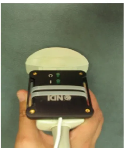
The robot has been sensorized with an optical sensor to be tracked by the optical Localizer(NDI Optotrak). The sensor is positioned for three reasons. At first to track medical instruments managed by the robot,
39 the second to obtain a closed loop control and the third one to refer robot position respect to the global frame.
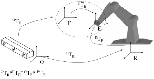
To move the robot end effector in respect to the global reference system, generally fixed or linked with the localizer, it is necessary to determine the geometric relation between the robot end-effector (E reference system) with the sensor frame (F reference system) and between the global reference system (O reference system) and the robot reference system (R reference system).
Fig. 3-2 Reference systems involved in the robot-localizer calibration, are :R= Robot Frame ; O= Global Frame; E= End-Effector Frame; F= optical sensors Frame. The transformation chain describing the relation between the four reference frames is:
OTR*RTE= OTF* FTE ( 1
Where the transformation OTF from the Optotrak base frame to the sensor frame (Fig. 3-2) is known by means of the lecture of the position sensor; RT
E is the transformation between the robot base frame to the end-effector frame, which is determined by the robot controller, which read joint encoders and calculate direct kinematic; OTR is the transformation from the Optotrak base frame to the Robot base frame,
40 which is unknown; also the transformation FT
E, from the end-effector frame to the sensor frame is unknown. The problem can be summarized in the simultaneous calculation of the last two unknown spatial relations.
Knowing OT
R and FTE it is possible to completely describe the transformation chain and so to control the robot end effector in the global reference frame (O), to track in real time robot end effector (and so a surgical instrument fixed on it), to control in a closed loop end effector right positioning.
The solution adopted in this thesis to calculate FT
E and thenOTR is shown in the following paragraph.
3.2 Robot Calibration
This problem is the same, in terms of transformation to determine, as another calibration problem, extremely important in the field of robotics, known as the ―hand-eye‖ calibration problem, where a camera ("eye") is mounted on the end effector ("hand") of a robot. For us the sensor can be considered as the camera in the ―hand-eye‖ calibration problem. A number of different solutions have been developed for this problem. The classical approach is ―Move the hand and observe/perceive the movement of the eye‖. The major part of existing solutions brings back to the resolution of a equations system of the type:
( 2
where A, B and X are transformation matrices.
It is possible reports the calibration process of the robot-localizer to the resolution of above equation, considering the reference frames in two robot poses, as shown in the following figure.
41 Fig. 3-3 Schematic representation of the AX=XB problem ; A: matrix describing the
position and orientation of the sensor frame relative to itself after the movement arbitrary; B: matrix that describes the position and orientation of the end effector with
respect to himself after the same movement; X: matrix that describe the static relation between the end effector and the sensor frame, (ETF)
To obtain an unique and exact solution it is sufficient only two pair of (Ai,Bi) satisfying some condition (independent movements).
But there are measure errors due the sensors. In particular, industrial robots are designed to be highly repeatable, but not very precise. For the Samsung robot the accuracy measured is of several millimeters (it was experimentally measured an worst case error of 7mm). Therefore K measures are performed to determine K couples (Ai, Bi). Given a set of N measurements of A and B, find X such that satisfies
42 Most approaches decompose the matrix X into its rotational and translational part and optimize for first the rotation and then the translation. The first works were of Shiu and Ahmad[61] (least squares fitting of rotation, then translation, using angle-axis representation) and Tsai and Lenz [62] (similar to [61] with closed form solution). Zhuang and Roth [63] simplified the formulation introducing quaternions for the estimation of the rotational part, in the same way as Chou and Kamel [64], who make use of the singular value decomposition (SVD). Park and Martin [65] perform nonlinear optimization using Euclidean Group. Zhuang and Shiu [66] apply nonlinear optimization for both parts, Fassi and Legnani [67] give a geometrical interpretation of these equations, making use of rototranslation and screws. Daniilidis [68] introduces the dual quaternions, an algebraic representation of the screw theory to describe motions. This enables the author to find a fast SVD-based joint solution for rotation and translation within linear formulation. Dornaika and Horaud [69] solve the rotational problem linearly with quaternions and also nonlinearly optimize both parts by one-to-one minimizing of Frobenius norms and two penalty functions. For this work, it was used an approach which was developed by Park and Martin in [65]. Despite the theoretically complexity of the algorithm (it is based on the matrix logarithm of the transformation matrix) it is extremely easy to implement.
Let ) be any rotation matrix and let be be the translation. Therefore, any valid transformation matrix M has the form:
( 3
If , the logarithm of this matrix is
43 where
and A is a matrix whose is irrelevant for solving the calibration problem.
Let be
( 5
The matrix logarithm [ω] is
( 6
This is a skew symmetric matrix
( 7
Therefore, [ω] can be parameterized as the vector [µ] where
( 8
The Park-Martin algorithm [65] attempts to find X
( 9
Equations that satisfied the hand-eye equation , and then the X is determined minimizing:
where d( .. .) is some distance metric on the Euclidean group.
Using the canonical coordinates for Lie groups the above minimization problem can be recast into a least-squares fitting problem that admits a simple and explicit solution. Specifically, given vectors x1, x2, x3, . . . xk and y1, y2, . . . , yk in Euclidean n-space it was provided explicit expressions for the orthogonal matrix Ө and translation b that minimize
k i i iX
XB
A
d
e
1)
,
(
44 b
The best values of Ө and b turn out to depend only on the matrix
By applying the canonical coordinates and this result a ―best-fit‘‘ solution to AX = XB can be obtained. The AX=XB can be expressed in term of rotational and translation part:
The algorithm decomposes the solution into two sub problems. The first is to calculate the rotation of , which can be carried out independently of the translations. The second problem calculates bX using the calculated value of .
( 10
( 11
– ( 12
The rotation matrix is chosen to minimise the cost function:
( 13
Let αi be the matrix logarithm of measurement αi and βi be the matrix logarithm of measurement Bi.
The optimal solution is
( 14