II
The completion of this work is the result of a period of collaboration and support from several people I am deeply indebted to.
First of all, I would like to express my deepest gratitude to Prof. Franco Mosca and my supervisor Prof. Mauro Ferrari for their supervision and for giving me the opportunity to make my PhD experience productive and stimulating working at the EndoCAS center. This thesis would not have been possible without their support.
I am deeply and sincerely grateful to my supervisor Dr. Vincenzo Ferrari for his valuable support, technical advices and friendly suggestions throughout my PhD course. His advices have been fundamental for the final results of this work.
I am also very grateful to Dr. Aldo Alberti, for his professional support and for all his contributions of time and ideas. The interest he has shown in my research has been stimulating for me.
I would like to thank all my current and erstwhile colleagues: Andrea, Cinzia, Cristina, Elena, Gianni, Giuseppe D., Giuseppe T., Marina, Orazio, Paolo, Liuba, Simona, Simone. I thank them for the beautiful moments we share together; I have learned something new from each one of them, and for that I am very grateful.
Among them I owe my deepest gratitude to Marina and Cinzia. Part of the work in this thesis has been developed thanks to their fundamental contribution.
III
I also would like to express my special thanks to Alessandra for her advices and her help to improve my English.
Last but not least, I thank my family, my friends and Lorenzo for their support and encouragements. Above all, I thank my parents who have always supported me during my studies.
IV
This thesis deals with two different but closely related issues: the study and development of an image guidance system for endovascular surgery and the definition of new strategies for innovative medical devices testing. More particularly, this work describes how to develop an electromagnetic navigator to aid the execution of endovascular procedures and to overcome drawbacks related to the fluoroscopic guidance modality, such as: loss of depth perception and spatial orientation (traditional C-Arms in fact provide bidimensional images); radiation exposure to staff and patient; adverse effects of contrast medium (administered for vessels visualization). Moreover an innovative methodology for the fabrication of realistic simulation environments is presented. The navigator assessment has in fact required the development of a testing environment compatible with fluoroscopy and CT imaging and able to realistically reproduce the morphology of the human vascular system. Currently available solutions on the market are in fact limited to the simulation of simplified standard models within a restricted database and thus are inadequate to reproduce technical difficulties of real endovascular procedures. For this purpose, a fabrication strategy to build an endovascular patient-specific simulator starting from the segmentation of real CT images has been developed. This procedure has been later extended to the development of silicone replicas of other anatomical structures and has been enriched with the possibility to add virtual simulation elements.
This work presents the most important outcomes obtained in each of the above mentioned research areas. A detailed description of the medical and technical background is reported; then, a strategy to develop a navigator allowing the real-time visualization of endovascular tools within the 3D model of the patient anatomy with no need for live fluoroscopy and contrast medium is proposed.
Abstract
V
Five DOFs electromagnetic sensors are calibrated and used for real-time tracking of position and orientation of endovascular catheters and guidewires, while Intraoperative 3D Rotational Angiography is used to acquire the 3D model of patient anatomy. A preliminary navigator prototype was developed to prove the feasibility of the system and to evaluate its accuracy and usefulness using an ad-hoc fabricated patient-specific simulator.
A detailed description of the fabrication strategy to build such kind of anthropomorphic simulator is reported. The proposed approach allows the fabrication of a single organ, district or apparatus, according to the need. It is not limited to the abdominal region, in fact the procedure can be extended to almost any other region of the body; moreover synthetic organs can be paired with sensors and enriched with a consistent virtual scenario. The target of this kind of surgical simulators is to offer the possibility to conduct systematic pre-clinical medical assessment of innovative devices and to obtain explicit guidelines that can improve the design process. Furthermore they can be used for surgical training purpose: they can offer resident surgeons the chance to learn how to perform a surgical task or an entire procedure, and in this way gain an improved awareness of surgical methods.
VI
Condino S., Ferrari V., Freschi C., Alberti A., Berchiolli R., Mosca F., Ferrari M. Electromagnetic Navigation Platform for Endovascular Surgery: How to Develop Sensorized Catheters and Guidewires. Accepted for Publication in: Int J Med Robot.
Condino S., Carbone M., Ferrari V., Faggioni L., Peri A., Ferrari M., Mosca F. How to Build Patient-Specific Synthetic Abdominal Anatomies. An Innovative Approach from Physical toward Hybrid Surgical Simulators. Int J Med Robot. 2011 Jun;7(2):202-13.
Condino S., Carbone M., Ferrari V., Alberti A., Cioni R., Forestieri F., Caramella D., Mosca F., Ferrari M. Fabrication Strategy to Build a Patient Specific Physical Simulator for Endovascular Training. Int J CARS 2011; 6(1): S272-S273.
Carbone M., Condino S., Ferrari V., Ferrari M., Mosca F. Surgical Simulators Integrating Virtual and Physical Anatomies. EICS4Med 2011; 1:13-18.
Condino S., Freschi C., Ferrari V., Berchiolli R., Mosca F., Ferrari M. Electromagnetic Navigation System for Endovascular Surgery. Int J CARS 2010; 5(1):S411–S412.
Contents
Contents
1
This chapter describes the background of the present doctoral work, introducing its core concepts and the main issues that will be addressed.
More in particular, it:
introduces basic concepts of endovascular surgery and analyzes in detail both the medical and technological background, pointing out advantages and drawbacks/technical difficulties, which can limit the success of the endovascular procedures. Moreover, a detailed technologic analysis highlights potentialities and limits of image-guided and robotic systems (experimental and commercial solutions), developed to improve the execution of endovascular procedures.
gives an overview of the principal applications of the simulation technologies, important not only for the preclinical assessment of innovative devices, but also for surgical/medical training purpose. The three exiting typologies of simulators (physical models, virtual reality simulators, and hybrid simulators) are described and the concept of "patient-specific" simulation is introduced.
Chapter 1 - Context of the Thesis
2
"Endovascular procedures are minimally invasive techniques that use a vessel (artery or vein) as the route to establish diagnosis or treat diseases" [1].
The growth of endovascular surgery has been characterized by innovations including stenting, balloon angioplasty, endoluminal grafting and atherectomy: techniques which allow surgeons to restore flow in occluded vessels and to repair aneurysms, percutaneously or with a minimal incision.
Endovascular procedures were initially complementary to open vascular surgical procedures in terms of the range of diseases that could be treated and endovascular options were indicated for patients with less severe vascular pathologies [2].
The continuous development of new devices and new surgical techniques has allowed surgeons to perform more complicated procedures and to successfully treat more complex lesions in older and sicker patients. Nowadays endovascular procedures appear to be a reasonable alternative to open surgery in most patients with open operations reserved for endovascular failures and complications [2-4].
Chapter 1 - Context of the Thesis
3
Wiring of an aortic aneurysm was probably the first endovascular interventional therapy. In the procedure, metal wires were introduced into the aneurysm through a thin needle to promote thrombosis. The first procedure was performed by Moore in 1864.
At that time, aneurysms could only be seen through surgical exposure: X-rays were to be discovered in 1895, and they alone would not show the arteries. In 1896, Haschek and Linderthal made the arteries in a cadaver’s hand visible under X-ray, but only through injecting chalk that obviously would have been poisonous for a living being. It was not until 1927 when Egas Moniz was able to discover a contrast agent tolerable to living humans, founding the technique of artheriography [5] and performing the first arteriogram in a human by direct puncture of the carotid artery. Since then, conventional angiographic techniques have been continuously refined to increase the procedures safety and the diagnostic effectiveness. Most important technical developments include a technique to facilitate the vessels percutaneous access, the Seldinger’s technique (Sven-Ivar Seldinger, 1953), and the development of digital subtraction angiography (Mistretta, 1973) [6].
One decade after Seldinger’s technique was first used, in 1963, Fogarty initiated the evolution of endovascular technology describing the first therapeutic use of a vascular catheter (balloon-catheter embolectomy and thrombectomy). Only one year later, in 1964, Dotter and Judkins introduced the concept of transluminal dilation and performed the first percutaneous transluminal angioplasty [7] (Figure 1.1).
Chapter 1 - Context of the Thesis
4
Figure 1.1. “If a plumber can do it to pipes, we can do it to blood vessels”: a
crossed pipe and wrench represent Dotter's “conceptual trademark”. Dotter realized that the key to a new medical specialty based upon endovascular interventions was the manufacture of catheters of various shapes and sizes. In 1963 Dotter met Bill Cook: the 1st dilation set, the “Dotter dilatation set,” was soon produced and used to perform the 1st percutaneous transluminal angioplasty [8-9]. Copyright © 2005 by Futura, an imprint of Blackwell Publishing.
Another milestone in endovascular evolution was the introduction of abdominal endograft: Parodi, in 1990, combined a Dacron graft and a balloon-expandable stent technology to build a stent-graft, which was successfully used to exclude an abdominal aortic aneurism from the systemic circulation.
Since then, many surgeons have significantly contributed in the development of endovascular procedure and ongoing technological advances have made it possible to treat the greater part of vascular diseases by minimally invasive means: nowadays endovascular procedure are performed not only by vascular surgeons but also by interventional radiologists, cardiologists, neurologists, neurosurgeons.
Chapter 1 - Context of the Thesis
5
Guidewires and catheters form the technical and conceptual basis of endovascular surgery, they enable percutaneous access and allow surgeons to reach the target area for diagnostic imaging and therapy. During an endovascular procedure, the access is obtained through arterial puncture1 (Figure 1.2 ) and catheters are advanced to the target lesion by coaxial movements of the devices along guidewires (See Appendix 6.2, "Overview on endovascular instruments" for more information on this topic).
Figure 1.2. Puncture of the common femoral artery: one of the preferred access
for most endovascular interventions. (a) A needle enters the common femoral artery. (b) A guide wire is passed through the needle. Modified from [10]. Copyright © 2007 WebMD, Inc.
1 The initial phase in endovascular surgery is the selection of the vascular access site. The
ideal access vessel is large, close to treatment site, free of diseases, and only minimally tortuous: such a vessel has lower probability to be associated with complications. For most endovascular procedure, the femoral artery is the preferred choice, even if the auxiliary, brachial, subclavian, common carotid and iliac arteries may also be used [10].
Chapter 1 - Context of the Thesis
6
The entire surgical procedure is performed under fluoroscopy and digital subtraction angiography2 guidance (Figure 1.3) in order to visualize in real-time the current position of surgical instruments (which have radio-opaque inserts) within the blood vessels (using contrast medium for their opacification).
Figure 1.3. Digital subtraction imaging (DSA) with marker pigtail catheter in
distal ascending aorta, guidewire advanced and curled around aortic valve and stent graft deployed covering left subclavian artery. Copyright © 2012 CTSNet [11].
Endovascular surgery has been widely adopted all over the world because it offers some immediate advantages over more traditional and highly invasive surgical techniques: no general anaesthesia, smaller incisions or lengthy incisions, shorter hospitalization, lower morbidity and mortality, less complicated reapplication in the event of a recurrent disease [12]. However, it also has some disadvantages.
2 Digital subtraction angiography (DSA) is a type of fluoroscopy technique used in
interventional radiology to clearly visualize blood vessels in a bony or dense soft tissue environment. Images are produced using contrast medium by subtracting a 'pre-contrast image' or the mask from later images, once the contrast medium has been introduced into a structure. Hence the term 'digital subtraction angiography' (from Wikipedia).
Chapter 1 - Context of the Thesis
7
First of all both the patient and the clinical staff are exposed to high radiation dose (13.4±8.6 mSv for endovascular aneurysm repair, EVAR [13]) and the radiographic contrast medium can have a nephrotoxic effect [14].
Moreover some technical difficulties can limit the success of the procedure and surgeons can have problems in reaching the target site (especially when the anatomy is complex). Convectional C-Arms in fact, provide only 2D projective images and the consequent lack of depth perception makes it difficult to visually estimate the position and orientation of catheters inside the patient vasculature. Furthermore, during the procedure, the physician has to perform several changes and re-adjustments of the C-Arm position and orientation: bad projection angles in fact can cause problems such as false vascular foreshortening and vessels obscuration due to overlying vessels or bones.
In addition, traditional catheters can be difficult to steer and to control, thus there being risks of complications such as vessels dissection or perforation.
The introduction of teleoperated robotic system into minimally invasive vascular surgery can effectively solve some of the above-mentioned problems. The teleoperation in fact can avoid any X-ray irradiation of the surgeon who stays away from the operating site and remotely manipulates the catheters under fluoroscopic images guidance. The robotic systems can also accurately control the tools, avoiding the tremor of surgeons’ hands: these systems in fact clamp guidewires and catheters and control their axial and rotational motions, allowing a precise positioning of these instruments within the human vasculature. In addition to these two controllable degrees of freedom (translation and rotation along catheters axis), some robotic systems also offer the possibility to control the catheter tip with a steering mechanism [15-16].
Chapter 1 - Context of the Thesis
8
Furthermore, various kinds of sensors can be integrated into catheters to measure position, force, flow, etc [17].
For all these reasons the robotic technology can certainly overcome the difficulties in controlling the instruments, while the perceptive difficulties associated with the traditional fluoroscopic guidance can be solved by using a 3D navigation system.
The following sections present the “state of the art” concerning navigations systems and robotic platforms developed for endovascular surgery, while Chapter 2 describes the innovative electromagnetic navigation system developed in the context of this PhD work.
The rapid development in the field of radiological imaging, computer graphics, virtual reality and image processing has produced initial works pertaining to the intra-operative guidance of endovascular and cardiovascular interventions.
Several methodologies can be used to acquire the representation (2D or 3D) of the patient anatomy and to monitor the position of endovascular instruments. The following paragraphs describe existing solutions, classifying them on the basis of this latter aspect.
A first class of systems is based on the segmentation of endovascular tools in fluoroscopic images. Other navigation systems aim to reduce the procedural radiation dose by using alternative localization strategies to follow the
Chapter 1 - Context of the Thesis
9
advancement of endovascular instruments inside the patient vasculature in real-time: these strategies are based on electromagnetic localization systems or rely on the measurement of electrical signals detected or emitted through electrophysiology catheter electrodes.
Moreover, several studies have proposed innovative methods to track and visualize endovascular instruments in the MRI environment.
Finally, new multimodal imaging strategies have been developed to overcome the limitations of traditional interventions: live fluoroscopic images with real time information on endovascular devices position can be registered with soft-tissue images acquired just before the intervention with a MR imaging system or a 3D C-Arm.3
A detailed state of the art and a description of the commercial systems currently available are described below.
Fluoroscopy Based Systems
Several methods have been proposed to segment and to track endovascular tools in fluoroscopic images. The reason for such research is either to enhance traditional fluoroscopic planar images and/or to generate a 3D representation of the surgical tools inside the vascular structures.
Palti-Wasserman et al. [25] began in 1997 with the tracking of guidewires during coronary arteries navigation. The aim of their work was to extract
3 An adjunctive imaging modality for the intraprocedural monitoring of endovascular
procedures is intravascular ultrasound (IVUS). This latters provide additional information superior to that of traditional angiography for the detection of endoleaks after stent-graft implantation, the identification of true and false lumen as well as the detection of slow flow in false lumens after stent-graft implantation [18]. For further information on this topic see [19-24].
Chapter 1 - Context of the Thesis
10
information about the mechanical function of the myocardium, reconstructing the movement (in 2D) of the guidewires inside the coronary arteries. Their algorithm is semiautomatic and includes a priori information about the guidewire shape and some characteristic of the images. It consists of two phases: the preprocessing and the tracking. First, radiographic images are filtered to enhance the linear structure of the guidewire. Then the guidewire is tracked in each frame with a second-degree polynomial function using the Hough transform. This algorithm is confined to a small active window to reduce calculation time and enhance tracking performance. Then the digitized tool is projected back on the live radiographic feed.
In 1999 Bender et al. [26] instead proposed an innovative image processing algorithm to extract the curve of one or more catheters in 3D space from two (or more) X-ray images (acquired with different projection angles) with an iterative reconstruction process.
Further research has subsequently proposed techniques to reconstruct the 3D catheter model from biplane images [27-29] and to visualize this 3D model in combination with pre-operatively acquired 3D images of the vasculature registered with the patient. This kind of algorithms are characterized by four main steps:
1. X-ray image distortion correction;
2. determination of the imaging system geometry (projection model); 3. tracking of the guidewire in the biplane images;
4. determination of the correspondence between structures in both projection images.
If the correspondence between structures in distortions corrected images is known, and if the C-Arm geometry is known, the 3D reconstruction is easy:
Chapter 1 - Context of the Thesis
11
the intersection of the lines from the focii to the points in the biplane images yields the 3-D reconstructed point (Figure 1.4).
Figure 1.4. Two pinhole cameras pointing at P (in real cameras, the image plane
is behind the focal point and produces a rotated image; here, the projection problem is simplified by placing a virtual image plane in front of the focal point of each camera to produce an unrotated image). OL and OR represent the focal
points of the two cameras, P the point of interest in both cameras. PL and PR are
the projections of P onto the image planes. Since the two focal points of the cameras are distinct, each focal point projects onto a distinct point into the other camera's image plane. The intersection of the lines respectively through OL and
PL and to OR and PR yields the 3-D reconstructed point (from Wikipedia).
An easy technique to determine this correspondence is to use the epipolar constraint as proposed by Baert et al. In [28] in fact they presented an automated method which tracks the guidewire simultaneously in biplane fluoroscopy images. The tracking procedure is based on the energy minimization of a spline parameterization of the guidewire in a feature image where line-like structures are enhanced. Then, to reconstruct the 3D position of the guidewire, pairs of corresponding points are determined in the two splines previously calculated in the biplane images. Knowing the projection
Chapter 1 - Context of the Thesis
12
parameters and the locations of the focal spots, the correspondences are finally solved using the epipolar constraint.
Other studies instead focalized on the segmentation of single plane fluoroscopy images. To reconstruct a 3D model of an object from only one projection image, distortion correction and imaging system geometry are as important as in the biplane case. There also is the need of additional information, such as the fixed configuration of an object as proposed by Hoffmann et al. [30] or the fixed distance between markers on the object [31]. A more complex method based on tracking a guidewire in monoplane fluoroscopic images is proposed by van Walsum et al. [32-33].
A particular application of the fusion between fluoroscopic intraoperative images and 3D models extracted from preoperative data sets is proposed by M. Feuerstein, et al. in [34]: they developed a segmentation and navigation tool for the endovascular stenting of the aortic aneurysms. In particular, their system includes a planning phase in which a modified graph cut algorithm automatically segments the aorta and aneurysm. During the implantation of the stent graft, after a landmark based registration of CT and angiography data, the current position of the stent can be visualized in the 3D CT data set: the stent position in the X-ray is marked interactively by the physician, then, an automatic visualization procedure projects back this 2D position into the 3D volume. This system aims to improve the accuracy of the placement of the stent-graft and helps in reducing the amount of contrast agents: in fact the contour of the segmented aorta can be displayed in 2D X-ray images without administering any contrast agent to the patient.
In conclusion it may be said that the segmentation and tracking of endovascular surgical tools on fluoroscopic images is useful to enhance the
Chapter 1 - Context of the Thesis
13
planar display and can be used in combination with 3D preoperative models of the patient vasculature to develop 3D guidance systems. These latter, avoid the use of any contrast agent but do not significantly reduce the radiation dose for patients and surgeons. Moreover several technical challenges still have to be overcome, for example the calculation time required for the tool segmentation is long [35].
Systems Based on the Electromagnetic Localization of Surgical Instruments
New techniques have been developed to partially replace fluoroscopic guidance with systems based on the integration of preoperative images and electromagnetic tracking data (a description of the electromagnetic tracking technology is reported in the Appendix). The main advantage of electromagnetic tracking systems over other localization systems is that no uninterrupted line-of-sight between the electromagnetic emitter (in general positioned close to the patient) and the sensors (in general mounted on the surgical instruments) is required: therefore, this strategy can be used to localize surgical instruments inside the body or under the patient’s skin [36].
Numerous studies have investigated the feasibility of navigation by using electromagnetic tracking information registered with preoperative data in order to replace the fluoroscopic guidance [37]. The accuracy and safety of electromagnetic tracking has been investigated in specific image guided procedures such as the targeting of liver tumors [38-39], guided bronchoscopy [40-43], thermal ablation and biopsy guidance [44], percutaneous puncture procedures based on C-Arm CT (CACT) images [45], percutaneous renal access [46] and transjugular intrahepatic portosystemic shunt (TIPS) procedure [47].
Chapter 1 - Context of the Thesis
14
[48-49] show the feasibility of using an electromagnetic localization technology, the Magellan, Biosense Webster Inc. (Magellan, Biosense Webster Inc., New Brunswick, NJ) to superimpose the real-time position of an ablation catheter tip on previously acquired 3D images of the heart and to perform catheter navigation without using additional fluoroscopic images. The Magellan system is based on an electromagnetic locator pad, a reference catheter and active procedural catheters. The locator pad, consisting of three coils, generates ultralow magnetic fields (5 × 10⁻⁵ to 5 × 10⁻⁶ T). Both the reference catheter and the procedural catheters have a position sensor, consisting of three orthogonal antennae, tracking the position and orientation of their tip. The system uses fiducial markers positioned on the patient skin for surface registration; the reference catheter is used to supply information about respiratory and positional changes in order to maintain the image registration. In [49] the electromagnetic data were merged with 3D MR images and the system was tested both in vitro and in vivo. During the in vitro tests, made using a phantom model, an accuracy of 1.116± 0.06mm (mean ± SEM) and a precision of 0.306 ± 0.07mm were obtained. During the in vivo test session, left and right heart catheterization was performed in 7 pigs without the use of fluoroscopy, yielding an in vivo accuracy and precision of 2.746 ± 0.52mm and 1.976 ± 0.44mm, respectively. In [48] the electromagnetic data were instead superimposed on a 3D CT. Catheter navigation was tested in the heart and the great vessels of a swine and an accuracy and precision of 4.69±1.70mm and 2.22±0.69mm were respectively obtained.
In [50] Pujol described a navigation system for an endovascular treatment of Abdominal Aortic Aneurysm (AAA) enabling a real-time localization of the endoprosthesis thanks to the registration between pre-operative CT scans, intra-operative 2.5D US data, and the magnetically tracked endoprosthesis
Chapter 1 - Context of the Thesis
15
delivery device. In [37] she also proposed a navigation system for neuro-interventional procedures which integrates the 3D visualization of the anatomy and the real-time electromagnetic localization of the endovascular tools using a point based registration algorithm (eight external fiducials are used to compute the registration matrix). The system was evaluated in vitro obtaining an overall accuracy of 2.7 ± 0.7mm and a maximal error on the distance of 3.6mm, for a set of 50 endovascular navigations to predefined targets.
More recently, in 2010 [51] a pilot study in swine was conducted to determine the feasibility of electromagnetic tracking as a method to augment conventional imaging for the positioning and deployment of thoracic aortic endografts. The study was conducted using an experimental, custom-modified, endovascular software derived of a commercially marketed image-guided intervention system (Traxtal, Philips Electronics). In vivo test demonstrated that the electromagnetic system can allow an accurate deployment of the stent graft near the target site (2.6mm deployment error).
Finally, in [52] a novel approach to arterial cannulation using the StealthStation® Guidance System [53] (Medtronic, USA) was described. The accuracy of the system was assessed in vitro by surgeons with different levels of experience in performing endovascular procedures. Each surgeon tried to cannulate the left subclavian artery using the conventional method and with the StealthStation®. The StealthStation® resulted accurate to less than 1mm and with this navigation system, every surgeon was able to complete the cannulation task with a significantly lower use of fluoroscopy than with the conventional method.
Chapter 1 - Context of the Thesis
16
System Based on Electrical Signals Detected or Emitted via Catheter Electrodes
The position of intracardiac catheter electrodes during electrophysiological procedures can be measured using an external electrical field, generated by surface electrodes positioned on the patient skin. This strategy, was proposed in 1997 by Wittkampf [54] and it is the basis for the functioning of the commercial navigation system LocaLisa® (Medtronic) [55].
Three skin-electrode pairs are used to apply three orthogonal alternating currents (1mA), with slightly different frequencies of about 30 kHz, through the patient's thorax. These currents create a voltage drop across internal organs such as the heart. The resulting voltage can be recorded via standard electrodes and it can be used to determine electrodes position. More particularly, presuming that the body behaves linearly, the location of the catheter tip can be calculated from the measured voltage after having calibrated the system. For doing that, a catheter with at least two electrodes must be employed. A simple calibration procedure, based on the knowledge of the inter-electrode distance and three quick measurements, can be in fact used to determine the correlation between the respective sensed x, y, z signals and the catheter position [54].
A similar localization strategy is employed in the CARTO 3™ (Biosense Webster): catheter electrodes are used to emit low-power/high frequency currents while surface patches are employed to detect such electrical signals. Then, a proprietary algorithm calculates the position of each electrode, based on the relative measured current (for further information see the paragraph
Chapter 1 - Context of the Thesis
17
To apply these concepts to catheter mapping and ablation procedures, cyclic variations due to cardiac pulsation and respiration must be offset and the electrical field must be harmless and must not interfere with electrocardiograms [56]. For what concerns this last point, 30-kHz signals are not expected to interfere with electrophysiological recordings and the 1-mA current level is in accordance with international safety standards.
Systems Based on Magnetic Resonance Imaging (MRI)
The non-ionizing nature of magnetic resonance imaging (MRI), its ability to combine the acquisition of high quality anatomical images and functional information, together with its inherent three dimensionality, make MRI an attractive technique for the guidance of endovascular procedures, for their planning and for the post-interventional follow-up [57]. The use of MRI allows the examination of serious complications such as vessel wall dissection or perforation. Moreover, it is very useful in case of completely blocked vessel segments (chronic total occlusions) which are virtually invisible in X-ray angiography since contrast medium cannot flow inside an obstructed lumen [58]. Another important advantage of MRI is the potential to perform functional measurements, such as flow measurements, during and after the surgical intervention [59].
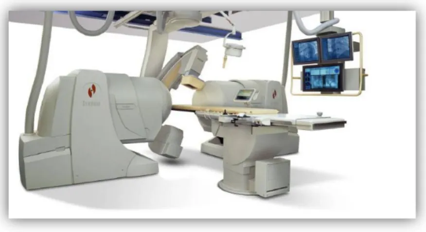
In the past, MRI has not been considered as an alternative imaging modality for endovascular surgery, mainly because of its relatively long image acquisition time, the closed nature of the magnets and the lack of MR compatible and safe equipment. Nowadays open and short-bore scanners (Figure 1.5) are available on the market and the development of stronger and faster gradient systems has enabled fast imaging: ultra-fast MRI can reach
Chapter 1 - Context of the Thesis
18
frame rates of 30/second, offering an alternative for the real-time monitoring of interventional procedures.
Figure 1.5. Different designs of interventional MR systems. a) 1.0-T vertically
oriented magnet, allowing patient access from head, foot, and from the side. b) A short (125cm) 1.5-T magnet with a 70-cm opening allowing transfemoral vessel access. Copyright © 2007, European Society of Radiology [60].
Several methods have been proposed to image and track flexible instruments (such as catheters and guidewires) in the MR environment [61], among them there are methods based on:
MR-Visible markers, positioned on the interventional instruments to amplify or reduce MR signal. Paramagnetic rings or magnetite mixture can be used to create a negative contrast small, whereas a positive contrast can be obtained with paramagnetic T1-shortening hydrogels or
contrast agents (which can be inserted inside the catheter lumen or applied to the catheter's internal/external surfaces) [61].
Direct Currents applied through catheters using integrated wires. These currents create a local magnetic field distorting the MR static magnetic field and resulting in a local signal void [61].
Chapter 1 - Context of the Thesis
19
Tracking and profiling RF coils incorporated into catheters and connected to the scanner receiver through coaxial cables. In active tip
tracking a non selective RF pulse is applied, which creates a transverse
magnetization in the MR system imaging volume. In the subsequent data acquisition only one spatial direction is encoded with a gradient echo and the signal detected with the catheter RF coils is only non vanishing at its projection onto the imaging axis. Repeating this procedure for the other two spatial directions the instrument position can be detected (within 20 ms) [61]. In a closely related technique, called MR profiling, a stretched RF coil incorporated into the device tip is used as a receiving coil for imaging. Because of the limited spatial sensitivity of such a coil, only spins in its direct vicinity will be visualized on the acquired images, leading to the depiction of the device over the total length of the coil. Graphical overlay techniques can be then used to superimpose the catheter tracking images onto any available road-map image [62].
Resonant RF micro-coils. In this case the interaction with the MR system RF field (B1) is used for instruments localization. Catheters are
designed to contain longitudinal single-loop RF resonant circuits consisting of a miniature high quality coil tuned to the Larmor frequency of the MRI system and surrounding a small container filled with a short T1 solution. The application of low flip angle4 excitation
pulses in a fast imaging sequence allows bright depiction of the coil’s interior due to the fact that the effective excitation angle inside the coil is increased because of the coil resonance (the resonant circuit locally amplifies the B1 field).
4 The flip angle is the rotation of the net magnetization vector by a radiofrequency pulse
Chapter 1 - Context of the Thesis
20
The signal from the coil's interior can be then acquired with a projection technique in all three spatial directions, to provide the position coordinate of the micro-coil [63-64].
Hall probes5
[65], coils or Faraday sensors6 [66] used to directly
measure the spatially varying gradient magnetic fields in order to determine the instruments position [61].
Table 1.1 summarizes the principal advantages and disadvantages of the above mentioned methods.
5 A Hall effect probe is a transducer that varies its output voltage in response to a magnetic
field. The measured voltage is proportional to the local magnetic field (and its orientation relative to the sensor) which, inside MR system imaging volume, is composed of the main field B0 and the spatially dependent magnetic field gradient. Since all the gradients used
during an imaging sequence are predetermined and known, the spatial position of the probe can be calculated from the measured Hall voltage [65].
6 The Faraday effect is a magneto-optical phenomenon which causes a rotation of the
polarization direction of a light beam in certain optically active media due to the application of an external magnetic field. Since the rotation angle is proportional to the magnetic field strength, the Faraday effect has found many applications in magnetic field measurements. A Faraday position sensor typically consists of a small optically active crystal connected to a light source and a detector via two optical fibres. To determine the position of the sensor, MR gradient fields are sequentially applied in all three spatial directions. The resulting rotation of the polarization direction is converted into a light intensity change, which is detected outside the MR scanner [66].
Chapter 1 - Context of the Thesis
21
Table 1.1. Advantages and Disadvantages of Published Tracking Methods for
Interventional Devices. Copyright © 2008 Wiley-Liss, Inc. [61].
As stated before, in addition to the technical difficulties connected to the instruments tracking, the translation of MR-guided techniques into clinical practice has been also limited by the lack of MR-compatible and safe equipment (such as MR guidewires) with mechanical characteristics similar to the standard one.
Standard instruments used in everyday clinical practice, in fact, contain electrically conductive components. Electrical currents, induced in those components by the RF pulses utilized in MR image acquisition, lead to redistribution of the pulses’ energy in an unpredictable manner, and cause an overheating of their conductors. Commercially available non magnetic
Chapter 1 - Context of the Thesis
22
guidewires made of Nitinol, that do not causing any artifacts in the MR images (as para or ferromagnetic wires do), can be sensitive to severe heating. It is well known that excessive and/or prolonged heating can determine undesirable, irreversible changes in the involved biological tissues [67-73].
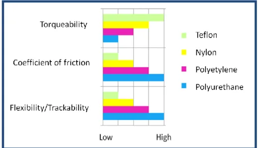
The problems related to metallic wires have led to the development of MR-visible guidewires made of fiberglass or PEEK (Polyether ether ketone) [74]. Recently, a 0.019inch guidewire prototype made with a micro-pultrusion technique using glass fiber-reinforced plastics materials was presented [75]. Although these new instruments are very encouraging, it still needs to be evaluated whether electrically non-conducting guidewires have the mechanical properties (eg, torsion stiffness, fracture stability) to replace standard metallic guidewires.
3D Multimodality Roadmapping: X-Ray Fused with Magnetic Resonance Imaging (XMR) and New 3D Rotational Angiography Systems
During minimally invasive interventions, the fluoroscopic images containing the live information on endovascular devices position can be merged with soft-tissue images acquired just before the intervention execution with a MR imaging system or a 3D C-Arm [76]. The fused image allows more accurate endovascular guidance during surgical procedures providing detailed 3D information regarding the vascular morphology and pathology. Moreover another clear advantage is that the amount of contrast agent can be reduced, since vascular structures can be visualized thanks to the preoperative data without injecting additional contrast medium [77].
Chapter 1 - Context of the Thesis
23
X-ray combined with magnetic resonance imaging, XMR, also known as XFM (X-ray Fused with Magnetic resonance imaging), can benefit from 3D information about vascular structures offered by MRI along with a large armamentarium of X-ray compatible catheters/guidewires [58]. Conventional XMR systems use an optimized patient transport system (Figure 1.6) between the angiography and MR patient table. This assures a high image quality both for the angiography as well for the MR imaging. Moreover, it enables an independent use of these modalities when a combined procedure is not planned [61].
Figure 1.6. An XMR system. An angiographic suite in front of 1.5 T MR system
in a separate room. An optimized system allows the transportation of the patient from on system to the other. Copyright © 2008 Wiley-Liss, Inc. [61].
In XMR systems, the 3D contours of anatomical structures extracted from MR are superimposed on live X-ray images. Catheter positions can be computed from 2 X-ray projections and back-displayed on a 3D MR roadmap. These views are updated as the C-Arm or table position changes. X-ray and MR can be co-registered using a shared table space, but patient movements
Chapter 1 - Context of the Thesis
24
lead to misregistration of data. To correct such kind of error, external fiducial markers positioned on the patient skin can be used to update the registration between MR and X-ray. Errors due to the respiratory and cardiac motion can be instead corrected using more sophisticated techniques [78]. XMR has been already clinically used in complex procedures such as the biopsy of the myocardial wall. Moreover it has been used in animal studies for the precise endomyocardial injections and complex repairs of membranous ventricular septal defects with significantly decreased fluoroscopy times.
An alternative approach to 3D-roadmapping is based on the fusion between the live fluoroscopy and the soft-tissue data acquired with a 3D Rotational Angiography (3DRA) system. With modern 3D C-arms, the 3D model of the vasculature can be acquired directly inside the surgical room, just before the intervention execution. Since 3DRA datasets7 are generated with the same imaging device as the 2D fluoroscopy images [79], it is possible to determine the registration matrix, based on the state of the geometry (viewing incidence angles, source-to-detector distance, etc.) and calibration data, with a
machine-based registration approach. This assumes that there is no patient motion
between acquisition of the 3DRA data and the fluoroscopic images. The advantage of machine-based registration over traditional image-based
registration is that the registration matrix can be computed also when there are
insufficient landmarks in the fluoroscopic images (due for example to the lack
7 A 3D rotational X-ray Angiography (3DRA) volume is reconstructed from a rotational
sequence of DSA images. In order to acquire a sequence of DSA images a first rotational sequence is acquired (by rotating the motorized C-arm around the patient), then the C-arm comes back to its original position and a second rotation sequence is acquired while the contrast medium is injected inside the patient vasculature. The high mechanical precision of modern motorized 3D C-Arm enables a perfect subtraction of the X-ray images. Finally, the 3D volume is reconstructed using a “back projection” technique similar to that used for CT to produce a 3D data set. The resulting volume is a high resolution 3D reconstruction of the vasculature subtracted from background material [79].
Chapter 1 - Context of the Thesis
25
of contrast medium). A further advantage of this methodology is the fact that it can be computed in real time [76-77].
Unlike XMR, 3DRA requires ionizing radiations to be used to acquire the 3D models of the patient anatomy. However recent studies have shown that using a3DRA means to cumulate a lower radiation dose than using only 2D angiography. In fact even if 3DRA series involve a larger number of 2D images (to reconstruct the 3D volume), depending on the exposed anatomical region, each single 2D image requires a dose that is 10 to 80 times lower than a traditional 2D DSA image. This means that a complete 3DRA scan is equivalent to less than 4 seconds of a 2D DSA acquisition at 4 frames per second [80-81]. To confirm this, a multicenter comparison [82] has shown that the use of 3DRA for carotid artery treatment involves a cumulative radiation dose three times lower than that used for procedures based only on 2D angiography, mainly because of a quicker selection of working projections and a consequent reduction in fluoroscopy time and number of 2D DSA series. The same study has come to the conclusion that there is a potential for significant radiation dose savings when a 3DRA acquisition is used instead of one or more biplanar DSA series in an interventional neuroradiology procedure.
Chapter 1 - Context of the Thesis
26
Commercial Navigation Systems and Catheters Locator Systems
This paragraph gives a brief description of commercial navigation systems available for endovascular surgery, cardiac mapping and minimally invasive electrophysiology procedures (EP). Finally other commercial systems to locate and track catheters are described.
The CARTO® System (Biosense Webster) [83] has been the first system to acquire, analyze, and display anatomical and electroanatomical maps of the human heart. It uses proprietary deflectable catheters available in various sizes (3.5mm, 4mm, 8mm). These catheters have an electromagnetic sensor at their distal end sending signals to the processing unit: the sensor measures the strength of the magnetic field generated by a unit mounted under the operating table (5 x 10⁻⁶ to 5 x 10⁻⁵ Tesla). A 3-D electro-anatomic map of any cardiac chamber of interest can be created with these catheters using a point by point mapping [84]. A significant advancement of this technology was the development of a hybrid magnetic and current based mapping system: the CARTO 3™ (Biosense Webster).
This is based on the following three elements:
1. ECG: the ECG subsystem supports receiving body surface ECG signals and up to 78 intracardiac (IC) electrogram channels. Local electrograms are acquired by catheters electrodes while touching the myocardial tissue.
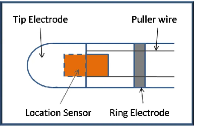
2. Location: the CARTO 3™ system includes two location technologies. • Information provided by magnetic sensors mounted on
catheters (Figure 1.7). Magnetic location technology employs an AC magnetic field generated by a location pad placed under
Chapter 1 - Context of the Thesis
27
the patient table to obtain accurate catheters location data. The mean positioning accuracy is 1mm.
• Advanced catheter location based on high-frequency, low-power current emission from every electrode in each catheter connected to the system. Six surface patches measure these currents. Then, a proprietary algorithm calculates the position of each electrode, based on the relative measured current. 3. Mapping: A mapping technology is used to build electroanatomical
maps of the heart chambers. These maps are built by combining the accurate location data and ECG data.
Figure 1.7. The locatable catheter is composed of tip and ring electrodes and a
location sensor totally embedded within the catheter.
Another important feature of this system is the possibility to merge the electroanatomical maps with preoperative images. By using an appropriate software module (CARTOMERGE Image Integration Software Module), in fact is possible to import and segment CT or MR image studies to reconstruct the three-dimensional surface of the desired cardiac structure. The system then allows the user to register the 3D surface with the electroanatomical maps
Chapter 1 - Context of the Thesis
28
with a process including a visual alignment or landmarks registration, followed by a surface registration. The surface registration is used to fit the surface image to the map surface based on the overall surface of the map (all acquired points or contours). Thus, the bigger number of points or contours are acquired, the better surface registration is obtained.
Other commercial systems are instead purely based on external electrical fields generated by electrode positioned on patient skin.
An example of this kind of system is the LocaLisa system® (Medtronic) [55] a non-fluoroscopic intracardial navigation system tracking multiple intracardiac electrodes. This system uses three skin electrode pairs, positioned in x,y,z directions around the heart to track catheters [56]. The catheters and desidered anatomical landmarks are displayed in a Cartesian reference frame.
An analogous system is the EnSite NavX™ (St. Jude Medical) for electro physiologic procedure [85]. This system consists of a set of three pairs of skin patches, a data module, a system reference patch, ten ECG electrodes, and a display workstation. It is based on currents across the thorax, developed as originally applied in the LocaLisa, but it can also allow the generation of the 3D geometry of the heart cavity. Sequential positioning of a catheter at multiple sites along the endocardial surface of a specific chamber in fact is used to establishes the chamber’s geometry (Figure 1.8). The system includes a segmentation tool and a registration module of preoperative CT or MR images [86].
Chapter 1 - Context of the Thesis
29
Figure 1.8. 3-D Graphical Displays of Cardiac Structures with EnSite System™
(from St. Jude Medical, Inc.). Copyright © 2008, Oxford University Press [87].
Finally, other commercial systems are based on the registration of live fluoroscopic image with 3D model of the patient anatomy.
An example of this kind of systems is the EP navigator (Philips) [88], for EP procedures. This navigator is based on the registration of live fluoroscopic data and a 3D image of the heart reconstructed from a pre-interventional CT image or an actual rotational angiography image. The system shows in real time the position of catheters in relation to the 3D anatomy of the heart.
The same concept underlies the functioning of the Dynamic 3D Roadmap [37] (Philips) for endovascular procedures. This system overlays real-time 2D fluoroscopy images and a 3D reconstruction of the vessel tree acquired intra-operatively or from a previous CT/MR scan (Figure 1.9). Imported data is registered to the current patient position through a low X -ray dose 3D-RA
Chapter 1 - Context of the Thesis
30
scan. This system adapts itself in real-time to changes in C-Arm angulations and rotations, field of view and source-image distance [89].
Figure 1.9. Example of stent deployment visible via 3D Roadmap. From Philips
website, Copyright ©2004-2012 Koninklijke Philips Electronics [89].
For what concerns the electromagnetic tracking of catheters three low cost catheters locator systems are currently available on the market: Cath Finder™ (Pharmacia Deltec), CathTrack™ (Bard Access Systems, Murray Hill, NJ) [90], Zortran (Lucent Medical Systems Inc.) [91].
Both Cath finder™ and CathTrack™ use a small coil in the catheter as a sensor and an external magnetic field generator. The position of the sensor can be calculated only if the emitting system is moved on a plane in order to remain close to the sensor, leaving only two degrees of freedom: depth and orientation in the horizontal plane. With a detection coil of 1mm in diameter, or less, the detection depth is 18cm and the accuracy is about 1cm [92].
Chapter 1 - Context of the Thesis
31
The Cath Finder system, was initially designed to facilitate the insertion of the PAS Port (Pharmacia Deltec), a long central venous catheter with an implantable chamber. It is based on a low intensity high frequency electromagnetic field. A pre-connected sensor guidewire is introduced into the catheter so as to make the catheter tip detectable by the electromagnetic field generated by a locator wand. When the centre of the field is being passed over by the sensor tip in the catheter-sensor assembly, a light signal is set off [93].
Similarly, the CathTrak® locator system has been designed to determine the location of the catheter tip during the placement of vascular access devices. It is a hand-held device, powered by a 9 volt battery. It provides an audible and visual signal to indicate the position and direction of a special wire stylet which has to connected to the locator, placed in the catheter during insertion, and removed when the catheter is in the desired position.
Finally, Zortran (Figure 1.10) is a system based a thin permanent magnet installed on the medical devices (for example, peripherally inserted central catheter, PICCs, and central venous catheters). It is a hand-held device for displaying the location and orientation of the distal tip of the medical instrument.
Chapter 1 - Context of the Thesis
32
Figure 1.10. Zortran system: the detector with a PICC catheter. The system is
able to display the location and orientation of the distal tip of the catheter. Copyright © 2004 Lucent Medical Systems, Inc.
Research on vascular interventional robots (VIR) has been carried out starting since the end of the twentieth century.
According to the difference in catheters actuation, vascular robots can be classified into four category: magnetic, pull-wire, smart material-actuated, and hydraulically driven. The magnetic and pull-wire technologies have already been clinically applied in two remote controlled catheter navigation systems, the Niobe® Magnetic Navigation System (Stereotaxis , USA) [94] and Sensei® robotic navigation system (Hansen Medical, USA) [95], even if they are both limited to specific surgical procedures. Other type of active catheters are now under investigation and have not been tested in vivo yet [15-16].
Chapter 1 - Context of the Thesis
33
Magnetic Systems
These systems are based on the use of a particular kind of catheter integrating small magnetic implants into their tip. These magnetic inserts act as magnetic dipoles and when immersed into a magnetic field are subjected to a magnetic moment: using two or more guiding magnets positioned near the operating table it is possible to generate an adjustable magnetic field for navigating the catheter to the desired position. In general these systems can improve both catheter propulsion, important to easily advance in the arterial tree, and catheter control, to easily perform the required curves and reach target areas.
The use of a magnetic catheter was first reported in 1951 by Tillander [96] who employed a single, moveable copper coil to navigate an articulated steel-tip catheter.
The first generation of commercial magnetic navigation systems, the Telsta® system (Stereotaxis , USA), was made of an orthogonal array of electromagnets surrounding the patient’s chest. This system was limited by the long response time (5–15 s) and the restricted working space. Moreover, liquid helium was required to cool the electromagnets and helium compressors created a thumping sound that was distracting and impaired communication between surgeons, nurses, and the patient [97].
The current generation is instead represented by the Niobe® Magnetic Navigation System (Stereotaxis , USA) [94], developed for cardiac interventional medicine, including arrhythmias, heart failure and coronary artery disease. The Niobe® is based on computer-controlled, externally applied magnetic fields that precisely govern the motion of the instruments tips
Chapter 1 - Context of the Thesis
34
(catheter, guidewire or other magnetic interventional devices); instruments advance–retract movements are instead controlled by a mechanical device (Figure 1.11). More in particular, the system (Figure 1.12) employs two permanent magnets mounted on articulating arms enclosed within a stationary housing, with one magnet on either sides of the operating table (these magnets create a spherical uniform magnetic field of 0.08T with an approximate diameter of 15cm) .
Figure 1.11. The automated catheter advancer is used to advance and retract a
catheter in the patient's heart while the NIOBE® magnets precisely steer the tip of the device. This allows the surgeon and clinical staff to perform an electrophysiology procedure from the control room, minimizing their x-ray radiation exposure (picture from [98] and Stereotaxis website).
Chapter 1 - Context of the Thesis
35
Figure 1.12. Stereotaxis Niobe® Magnetic Navigation Systems. Overview of the whole system (from http://www.device.co.nz). Copyright Stereotaxis 2011.
The remote instrument control is based on user friendly “point and click” and/or joystick-operated technology. Compared to Telstar, Niobe® is more reliable and silent, the response time is shorter (within 1–3 s) and the imaging device has a larger working space. Furthermore, it employs redesigned catheters with three small magnets in a linear array to enable smoother transition across the tip (14) (Figure 1.13). Dimensions of the magnetic catheters/ guidewires are as follows: the Celsius® RMT and Navistar® RMT diagnostic and ablation catheters are 7 Fr (1 Fr = 1/3mm) and 7.5 Fr in diameter; the magnetic coronary guidewire Titan® is 0.04 inches (0.36mm) in diameter.
Chapter 1 - Context of the Thesis
36
Figure 1.13. A magnetic catheter outside the magnetic field. This is extremely
flexible. There are magnets in the tip and underneath the two blue markers on the distal shaft just next to the tip (picture from [98] and Stereotaxis website).
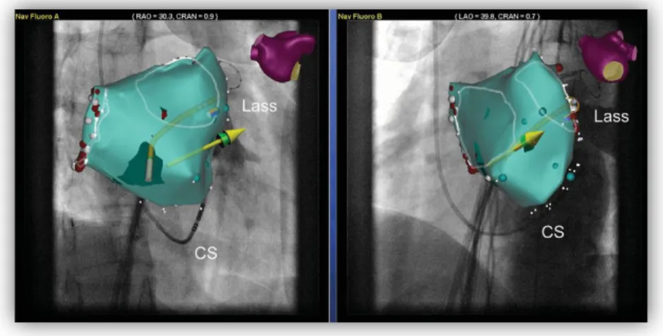
The Stereotaxis Niobe® Magnetic Navigation System can be integrated with the Electroanatomical Navigation System of Biosense Webster technology: the resulting system, the CARTO RMT Electroanatomical Navigation System (Biosense Webster) [99], enables the closed-loop navigation of magnetically steered catheters (Figure 1.14).
Chapter 1 - Context of the Thesis
37
Figure 1.14. Screenshot of Navigant workstation of the magnetic navigation
system. A three-dimensional electroanatomical reconstruction integrated in a fluoroscopic picture from two different angulations is shown. The yellow and green arrows show the vector of the magnetic field. Copyright © 2008, Oxford University Press [100].
Cable Actuated Systems
Cable actuation is another approach to develop steerable catheters and to simplify their control in the arterial tree. A simple mechanism with 1 DOF is shown in Figure 1.15. It consists of a leaf spring and a spring steel wire running parallel to each other, as well as a helical spring winding around. By fixing both sides of the leaf spring to the bending segment it is possible to provide enough rigidity, the helical spring is instead used to keep the catheter shape. By pulling a wire fixed to the catheter tip it is thus possible to bend the leaf spring and consequently the catheter. Different bending angles can be obtained by varying the extension of the pull-wire, while the number of DOFs can be increased distributing two pull-wire pairs around the circumferential direction [16].
Chapter 1 - Context of the Thesis
38
Figure 1.15. A simple cable actuation system with 1 DOF. Modified from [16].
Copyright © 2009 John Wiley & Sons, Ltd.
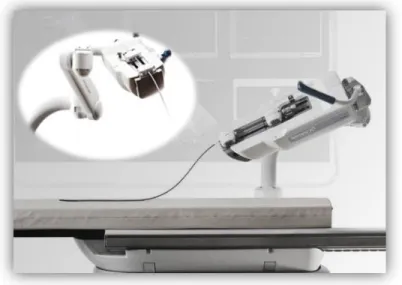
An example of cable actuated robot is the Sensei robotic navigation system (Hansen Medical, USA) [95], a novel electromechanical master/ slave system, developed for mapping and ablation procedures. The Sensei system is teleoperated via an OMEGA Haptic Device and supplies haptic feedback. Catheter navigation is obtained using an “Artisan control catheter” that is composed of two guiding steerable sheathes (ArtisanTM, Hansen Medical, USA). The ArtisanTM has six degrees of articulation and a variable bend radius which facilitates catheter maneuverability to reach difficult anatomical locations (Figure 1.16).
Chapter 1 - Context of the Thesis
39
Figure 1.16. ArtisanTM manipulator. The system has six degrees of articulation.
(from Sensei robotic navigation system brochure). Copyright © 2012 Hansen Medical, Inc.
The outer (14F) and the inner sheath (10.5F) are both manipulated via a pull-wire mechanism by a sheath carrying robotic arm fixed to the operating table. The outer sheath, controlled by two pull wires 180° apart, provides a stable base for the inner guide, the inner sheath is deflected by four orthogonal pull-wires and has toroidal workspace. Conventional 8 Fr or smaller catheters (mapping and ablation catheters) are inserted through the inner guide catheter and locked into place at the proximal end of the Artisan. An advantage of Sensei is that, unlike the Niobe® system which can only be combined with CARTO, it can be used with any 3D-mapping system (Figure 1.17). Particular application of the Sensei System in the field of endovascular aneurism repair are described in the literature by C. Riga et al. who tested innovative procedures in animal models [101] [102].
Chapter 1 - Context of the Thesis
40
Figure 1.17. Screenshot of the Sensei workstation. The blue virtual catheter
displays the intended orientation of the steerable sheath. In the right upper panel: virtual three-dimensional dots saved during a mapping procedure. Right lower panel: A camera provides a permanent view to the patient table. Copyright © 2008, Oxford University Press [100].
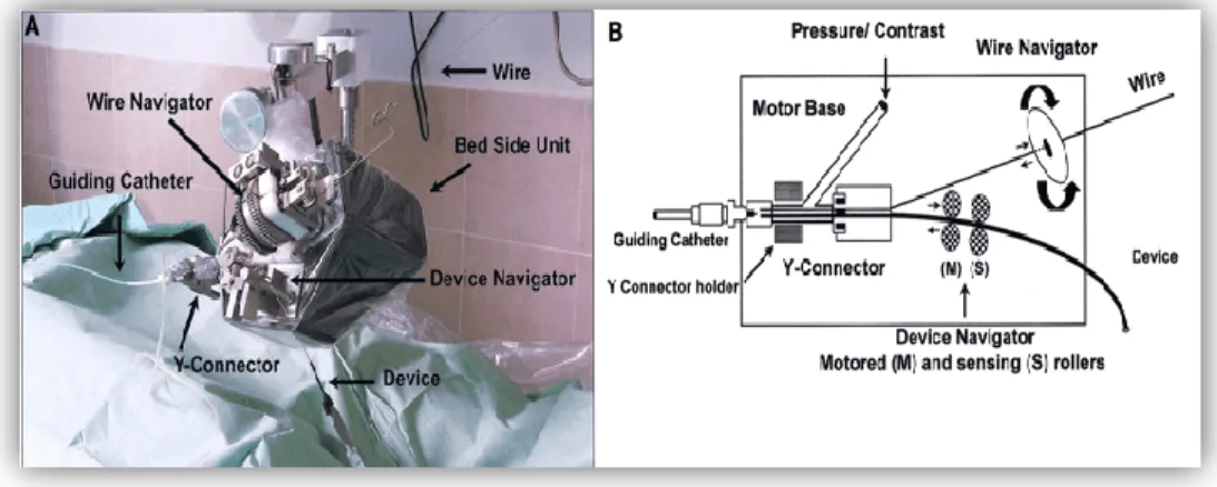
Another cable actuated system is the telerobotic system proposed in [103-104] for the remote manipulation of standard steerable electrophysiology (EP) catheters (CathROB08, Tre Esse Progettazione Biomedica s.r.l., Bologna, IT). This electromechanical system does not require dedicated catheters and devices. It allows the surgeon to remotely control the catheter movements from an X-ray shielded workstation by using a joystick connected to the control unit. The driving unit principally consists of controllable actuators which transmit to catheters: a longitudinal movement of advance/withdrawal, a clockwise/counter-clockwise rotating movement (about the catheter longitudinal axis) and a steering movement of the tip. The driving unit is equipped with a force sensor to measure the resistance encountered by the catheter while advancing [103-104].
Chapter 1 - Context of the Thesis
41
Smart Material Actuated Systems
Smart material-actuated catheters use materials with special electrical and mechanical properties as actuators. Currently two typologies are principally used: shape memory alloy (SMA) and ionic polymer–metal composite (IPMC).
The working principle of the first type of catheters is based on the heating of the SMA actuators that shrink and bend the catheter. When heating stops, thanks to its elasticity, the catheter recovers its initial state.
An SMA actuated system has been described by Fu et al. [105] who developed a system consisting on a shape memory alloy active catheter (made of a bias spring in the centre and three distributed SMA actuators) integrated with two Aurora electromagnetic sensors. The system control strategy is based on the generation of a navigation path extracted from 3D preoperative image by generating the skeleton of 3D vessel models. The position of the catheter tip (monitored with a magnetic tracking system) is automatically adjusted on the basis of the generated navigation path.
A major problem in SMA-actuated catheters is that too many lead wires are required for controlling the actuators: the total number required is at least equal to the number of the actuators used.
IPMC consists instead of a proton exchange membrane (PEM) between two metal electrodes. Applying an electric potential (1–2 V) it is possible to obtain large bending deformation toward the anode. IPMC technology was first employed as a bending actuator for a catheter by Guo et al. [106].
![Figure 1.9. Example of stent deployment visible via 3D Roadmap. From Philips website, Copyright ©2004-2012 Koninklijke Philips Electronics [89]](https://thumb-eu.123doks.com/thumbv2/123dokorg/7559847.110360/41.918.339.634.255.582/example-deployment-roadmap-philips-copyright-koninklijke-philips-electronics.webp)