Research Article
Stochastic Seismic Analysis and Comparison of
Alternative External Dissipative Systems
Laura Gioiella
,
1Enrico Tubaldi,
2Fabrizio Gara,
3Luigino Dezi,
3and Andrea Dall’Asta
1 1School of Architecture and Design, University of Camerino, Viale della Rimembranza, 63100 Ascoli Piceno, Italy2Department of Civil and Environmental Engineering, University of Strathclyde, 75 Montrose Street, Glasgow G1 1XJ, UK 3Department of Civil and Building Engineering and Architecture, Universit`a Politecnica delle Marche, Via Brecce Bianche,
Ancona, Italy
Correspondence should be addressed to Laura Gioiella; [email protected] Received 15 September 2017; Accepted 27 December 2017; Published 29 January 2018 Academic Editor: Ivo Cali`o
Copyright © 2018 Laura Gioiella et al. This is an open access article distributed under the Creative Commons Attribution License, which permits unrestricted use, distribution, and reproduction in any medium, provided the original work is properly cited. This paper deals with the seismic retrofit of existing frames by means of external passive dissipative systems. Available in different configurations, these systems allow high flexibility in controlling the structural behaviour and are characterized by some feasibility advantages with respect to dissipative devices installed within existing frames. In particular, this study analyzes and compares the performances of two external solutions using linear viscous dampers. The first is based on the coupling of the building with an external fixed-based steel braced frame by means of dampers placed horizontally at the floor levels. The second is an innovative one, based on coupling the building with a “dissipative tower,” which is a steel braced frame hinged at the foundation level, and activating the dampers through its rocking motion. The effectiveness of the two solutions is evaluated and compared by considering a benchmark existing reinforced concrete building, employing a stochastic dynamic approach, under the assumption of linear elastic behaviour for the seismic performance evaluation. This allows efficiently estimating the statistics of many response parameters of interest for the performance assessment and thus carrying out extensive parametric analyses for different properties of the external systems. The study results provide useful information regarding the design and the relative efficiency of the proposed retrofit solutions.
1. Introduction
Traditional approaches for the seismic performance enhance-ment and retrofit of buildings by means of passive damping usually involve installing the dissipative devices within the building frame in either diagonal or chevron braces connect-ing adjacent storeys [1, 2]. This type of dampconnect-ing configuration has been extensively studied in the last decades both experi-mentally and numerically, with a significant number of works focusing on design criteria and performance assessment [3– 11]. However, the use of dampers within building frames presents some disadvantages, especially when employed for the retrofit of existing buildings. The increase of internal actions in the nodes and columns adjacent to the dampers can induce premature local failures [10], strengthening the foundations is generally required, retrofitting operations cause remarkable downtime, and relevant costs must be
sustained. For these reasons, there is an increasing interest on external passive control systems, characterized by minimized interferences with the existing frame, during the installation of the retrofit system and also during the building operation. External damping systems are available in different config-urations [11–13], allowing high flexibility in controlling the structural behaviour, but their relative efficiency in terms of seismic performance has not been fully investigated to date. In fact, most of the studies in the literature focus on the most recurrent configuration involving the coupling of the structure to be protected with an external one by means of dampers placed horizontally at the storey level (Figure 1(a)). The external structure can be stiff, or it can be flexible, as in the case of adjacent buildings with different dynamic properties [14–18]. The dampers are activated by the absolute floor displacements in the first case and by the relative floor motion of the systems in the latter one. It is noteworthy that Volume 2018, Article ID 5403737, 16 pages
(a) (b)
Figure 1: Coupling of the existing frame with (a) external fixed-based (FB) structure; (b) rocking-base (RB) tower.
the first configuration can also be designed to achieve mass proportional damping, where the viscous damping constants are proportional to the floor masses [12].
Recently, an innovative external retrofit configuration, denoted as “dissipative tower,” has been proposed. This consists of an external stiff braced structure rigidly linked to the frame at floor levels and connected at the foundations by a hinge (Figure 1(b)). Fluid viscous dampers (FVDs) placed at the base of the external frame and activated by its rocking motion provide energy dissipation to the system, whereas the high stiffness of the braced frame induces a uniform distribu-tion of the interstorey drifts of the protected frame [19].
It is noteworthy that the use of rocking systems has emerged in the last few years as an efficient way to reduce seismic damage [20] and different solutions are available for coupling the frame and the external pinned rocking struc-tures [21, 22]. The rocking tower considered in this study has been employed for the seismic design of new constructions and for retrofitting existing buildings [23, 24] by using a patented technical solution [25]. However, its effectiveness has not been compared yet to the one of more diffused systems involving the coupling between two structures by means of viscous dampers placed horizontally at the floor level.
In this paper, a performance comparison between the two retrofit configurations, that is, the fixed base structure with horizontal FVDs and the rocking tower with vertical FVDs at the base, is carried out through a parametric analysis involving a reference existing building, widely studied in the past [26–28]. The performance comparison is made first in terms of dynamic properties, that is, vibration periods and damping ratios, and then in terms of seismic response of different engineering demand parameters (EDPs) of interest for the safety assessment of the building, the external brac-ings, and the dampers. In the analyses, the system behaviour is assumed as linear, and the earthquake input is modelled as a stationary stochastic process. Under these assumptions, the problem can be analyzed in the frequency-domain and already available stochastic dynamics techniques [29, 30] can be efficiently used to obtain closed-form expressions of the seismic response statistics, expressed in terms of standard deviation and peak values of the EDPs of interest for a finite time of observation. This approach allows investigating and comparing a wide range of configurations, corresponding to different levels of stiffness and damping of the external systems. The study results give useful information regarding
the design of the external configurations and their relative efficiency for retrofitting existing buildings. It is noteworthy that the elastic behaviour assumption for the problem at hand is reasonable since for practical design applications linear FVDs are often designed in external retrofit systems in such a way as to enhance the performance levels for the building avoiding damages to the structural building components (e.g., immediate occupancy or operational performance level, corresponding to negligible structural damage).
2. Problem Formulation
The reported formulation is suitable for both the two external arrangements; under the assumption of linear elastic behav-iour, the equation of motion of the system can be expressed in general as
M ̈u (𝑡) + C ̇u (𝑡) + Ku (𝑡) = Mp𝑎𝑔(𝑡) , (1)
where u(𝑡) ∈ 𝑅𝑙is the vector of nodal displacements and
rotations; the dot (⋅) denotes time-derivative; p ∈ 𝑅𝑙 is
the load distribution vector;𝑙 denotes the total number of
degrees of freedom; and𝑎𝑔(𝑡) is the external scalar loading
function describing the seismic base acceleration. The time
constant matricesM, K, and C describe the mass, stiffness,
and damping operators𝑅𝑙 → 𝑅𝑙; they account for the
con-tribution of both the existing frame and the external dissipa-tive bracing system.
Generally, the external bracing system is introduced mainly to control the stiffness and the damping of the system to be protected, while it contributes only marginally to the global mass. In order to give evidence of this aspect in the formulation, it is assumed that the bracing mass is null, and
the total displacement vectoru(𝑡) is split into the vector x(𝑡) ∈
𝑅𝑚, collecting the active components related to the inertia
forces acting on the frame, and the vectory(𝑡) ∈ 𝑅𝑛(with𝑙 =
𝑚+𝑛), collecting the other components related to the internal degrees of freedom, including the displacement of the bracing providing the damper deformation. The differential problem is consequently partitioned as follows:
[ M𝑥𝑥 0 0 0 ] [ ̈ẍy] + [CC𝑥𝑥𝑦𝑥 CC𝑥𝑦𝑦𝑦] [ ̇ẋy] + [KK𝑥𝑥 K𝑥𝑦 𝑦𝑥 K𝑦𝑦] [xy] = [ −M𝑥𝑥p𝑥 0 ] 𝑎𝑔. (2)
In the following, the plane problem is considered, by intro-ducing usual simplifications for seismic frame analysis: the floors are assumed to be rigid, only the horizontal component is considered for both the ground motion and the active masses, and these latter are concentrated at the storey levels.
In this case, the dimension 𝑚 of the vector x(𝑡) coincides
with the number of storeys, and additional𝑛 degrees of
free-dom, collected iny(𝑡), are required to describe the damper
deformation.
In the case of the “dissipative rocking tower,” the link between the frame and the bracing at the storey levels is
rigid, soy(𝑡) collects only the vertical displacements related
to the rocking motion of the tower at the damper locations.
The tower base motion described byy(𝑡) induces an elastic
deformation of the bracing and a set of reactions at the different building floor levels, described by the submatrix
K𝑥𝑦. Similarly, the motion of the building floor results in
reactions at the base of the tower, described by the submatrix
K𝑦𝑥 = K𝑇
𝑥𝑦. The damper reactions due to the motion of the
base of the tower are described by the matrixC𝑦𝑦.
In the case of the “fixed-based structure,” y(𝑡) collects
the bracing displacements at each floor level, and the damper deformations are induced by the relative motion between the frame and the external structure. In this case, the elastic
matricesK𝑦𝑥andK𝑥𝑦are null, whereas the elastic response
of the bracing is described byK𝑦𝑦. Both the motions ofx(𝑡)
andy(𝑡) produce damper forces and all the submatrices of C
are different from zero.
Nevertheless, both the retrofit configurations induce non-classical damping because the distribution of the dampers results in a damping matrix which is not proportional to the global mass matrix, nor to the stiffness matrix. The rocking tower corresponds to a highly nonclassically damped system, since the viscous energy dissipation is mainly concentrated at the base of the tower. The second configuration, with the fixed-based bracing, is often characterized by a damping distribution similar to the mass distribution, and it is closer to a classically damped system.
In the following applications, an inherent damping factor equal to 0.05 is also introduced through a Rayleigh damping matrix [31] to provide a realistic description of the response without the added dampers.
2.1. Modal Properties. For the solution of the dynamic
prob-lem, corresponding to𝑎𝑔(𝑡) = 0 in (2), a state-space approach
is convenient because it gives the opportunity to perform the complex modal analysis of the coupled system, leading to the knowledge of the modal properties in presence of nonclassi-cal damping. For this purpose, it is useful to introduce the
vector k(𝑡) = ̇x(𝑡) and the state vector z(𝑡) = [x(𝑡), k(𝑡),
y(𝑡)]𝑇, collecting the displacements and the velocities of the
active displacements and the displacements of the internal nodes. Equation (2) can be reduced to a first-order state space
form ̇z(𝑡) = Az(𝑡), where the (2𝑚 + 𝑛)-dimensional state
matrixA is expressed as A =[[[ [ 0 I 0 −M−1 𝑥𝑥(K𝑥𝑥− C𝑥𝑦C−1𝑦𝑦K𝑦𝑥) −M−1𝑥𝑥(C𝑥𝑥− C𝑥𝑦C−1𝑦𝑦C𝑦𝑥) −M−1𝑥𝑥(K𝑥𝑦− C𝑥𝑦C−1𝑦𝑦K𝑦𝑦) −C−1 𝑦𝑦K𝑦𝑥 −C−1𝑦𝑦C𝑦𝑥 −C−1𝑦𝑦K𝑦𝑦 ] ] ] ] . (3)
Assuming a solution of the formz(𝑡) = 𝜑𝑒𝜆𝑡, the
eigenvalue-eigenvector pairs ofA, that is, 𝜆, 𝜑, are obtained by solving
the eigenvalue problem:
A𝜑 = 𝜆𝜑. (4)
In general, a complex eigenvalue has the form
𝜆𝑖= −𝜉𝑖𝜔0𝑖+ 𝑖𝜔0𝑖√1 − 𝜉2
𝑖 (5)
and contains information regarding both the damping ratio
𝜉𝑖 and the corresponding undamped circular frequency𝜔0𝑖
of the𝑖th mode:
𝜔0𝑖= 𝜆𝑖
𝜉𝑖= −Re (𝜆𝜆 𝑖)
𝑖 .
(6)
It is noteworthy that the eigenvalues are (2𝑚 + 𝑛) in total: 2𝑚 of these are complex conjugates, and the remaining 𝑛 are real-valued and correspond to the motion of the degrees of freedom with no associated mass.
Closed-form expressions useful for the damper design can be obtained for both the external arrangements by intro-ducing some simplifying assumptions. In the case of coupling with a fixed-based bracing, the dampers can be designed assuming the dampers constants distributed proportionally
to the floor masses, that is, the damper constant𝑐𝑑𝑖 at the
𝑖th floor can be expressed as 𝑐𝑑𝑖 = 𝛼𝑀𝑖, where𝛼 is the
pro-portionality constant and𝑀𝑖 = [M𝑥𝑥]𝑖𝑖is the floor mass. In
the limit case of infinitely stiff contrasting structure, a multi-degree of freedom system with mass proportional damping, which is classically damped, is obtained. Thus, the circular frequencies of the coupled system are the same as those of the undamped one, and the added damping ratio for the modes of the system is
𝜉add,𝑖 = 𝛼
2𝜔𝑖, (7)
where𝛼 and thus the values of 𝑐𝑑𝑖can be calibrated to achieve
a prefixed added damping ratio in correspondence of the first mode of the bare frame.
In the case of the rocking tower, a simplified expression for the damper design can be obtained by assuming infinitely
rigid bracings. Under this assumption, the system acts as a single-degree of freedom, the displacement shape is linear along the building height and controlled by the base rotation
𝜓, that is, u = 𝜓h, where h = [ℎ1, ℎ2, . . . , ℎ7, 𝑏/2, 𝑏/2]𝑇 is
the vector collecting the floor heights and half of the external
bracing frame width𝑏. The corresponding circular vibration
frequency and added damping ratio due to the dampers located at the tower base are
𝜔2=𝜑𝜑𝑇𝑇M𝜑K𝜑 =hh𝑇𝑇MhKh
𝜉add=
𝑐𝑑𝑁𝑑𝑏2/4
2𝜔h𝑇Mh,
(8)
where𝑐𝑑is the viscous constant of the𝑁𝑑dampers located at
the tower base. As previously, the value of𝑐𝑑can be calibrated
to achieve a prefixed value of the added damping ratio for the system.
2.2. Stochastic Formulation of the Seismic Problem. The
prob-lem can be solved in the frequency-domain, rather than in the time-domain [32]. It is noteworthy that resorting to the frequency-domain has the advantage of allowing for a condensed description of the seismic problem, in terms of the active degrees of freedom only. Moreover, it permits to conveniently estimate the response to the uncertain input by exploiting already available stochastic dynamics techniques.
By denoting withx and y the Fourier transforms of the
vectors collecting, respectively, the active degrees of
free-dom and internal degrees of freefree-dom and with𝑎𝑔the
trans-formed external scalar loading function, representative of the seismic base acceleration, the differential system of (2) can be rewritten as an algebraic system:
[−𝜔2M𝑥𝑥+ H𝑥𝑥 H𝑥𝑦
H𝑦𝑥 H𝑦𝑦] [xy] = [−M0𝑥𝑥p𝑥] 𝑎𝑔, (9)
whereH𝛼𝛽= 𝑖𝜔C𝛼𝛽+K𝛼𝛽, for𝛼, 𝛽 = 𝑥, 𝑦, and 𝜔 is the circular
frequency.
Based on (9), the internal displacements can be expressed
in function ofx as
y = −H−1𝑦𝑦H𝑦𝑥x. (10)
After substituting (10) into (9) and rearranging, the following condensed problem is obtained, where the active displace-ments can be directly related to the base motion through the expression:
x = H (𝜔) 𝑎𝑔, (11)
whereH(𝜔) = −M𝑥𝑥[−𝜔2M𝑥𝑥+ H𝑥𝑥− H𝑥𝑦H−1𝑦𝑦H𝑦𝑥]−1p𝑥is
the transfer function vector for the problem.
It is noteworthy that both the external damping solutions can be formally expressed in terms of the condensed problem of (11). Thus, the transfer functions of the two systems can be directly compared one to each other and also to the transfer function of the bare frame in order to shed light on the effects of the different types of retrofit.
Moreover, the transfer functions can be useful to estimate the statistic of the response under a stochastic earthquake input. If both the earthquake input and the response are con-sidered stationary, the Power Spectral Density (PSD) of the
outputΦxx(𝜔) can be expressed as follows [29]:
Φxx(𝜔) = H∗(𝜔) Φ𝑎𝑔𝑎𝑔(𝜔) H
𝑇(𝜔) , (12)
whereΦ𝑎𝑔𝑎𝑔(𝜔) is the PSD of the earthquake input and H∗(𝜔)
is the complex conjugate of the transfer function vector.
The variance of the𝑖th floor displacement response 𝑥𝑖can
be obtained as 𝜎𝑥2𝑖 = 2 ∞ ∫ 0 [Φxx(𝜔)]𝑖𝑖𝑑𝜔, (13)
where [Φxx(𝜔)]𝑖𝑖 denotes the element of matrix Φxx(𝜔) in
correspondence of row𝑖 and column 𝑖.
Finally, approximate estimates of the peak values of
displacement 𝑥𝑖 can be obtained based on the concept of
the peak factor𝜂𝑝[30]. The expected value of𝜂𝑝, evaluated
according to the Davenport formula, is
𝐸 [𝜂𝑝] = √2 log (𝜔𝑐𝑡𝐿
𝜋 ) +
0.5772
√2 log (𝜔𝑐𝑡𝐿/𝜋), (14)
where𝜔𝑐 = 𝜎̇𝑥𝑖/𝜎𝑥𝑖, is the central frequency, that is, the ratio
between the standard deviation of the velocity and of the
displacement of the response, and𝑡𝐿is the time interval of
observation.
The expected value of the maximum displacement
response amplitude is thus given by𝑥𝑖max = 𝐸[𝜂𝑝]𝜎𝑥𝑖. The
standard deviation of the velocity response𝜎̇𝑥𝑖 can be found
as 𝜎2̇𝑥𝑖 = 2 ∞ ∫ 0 𝜔2[Φxx(𝜔)]𝑖𝑖𝑑𝜔. (15)
The Fourier transformq of the vector collecting any other
response parameter of interestq (e.g., floor accelerations, base
shears) can be related tox through the linear operator B(𝜔).
Consequently, the PSD ofq can be obtained as follows:
Φqq(𝜔) = B (𝜔) Φxx(𝜔) B (𝜔)𝑇. (16)
The corresponding peak response value for the𝑖th
compo-nent ofq can be found by considering in (14) the relevant
expression of the central frequency; that is,𝜔𝑐= 𝜎̇𝑞𝑖/𝜎𝑞𝑖.
3. Case Study and Seismic Hazard
The Van Nuys building [26–28] is a 7-storey 3 bay-by-8 bay cast-in-place r.c. moment resisting frame building, with nonductile column detailing, designed in 1965 in compliance to the lateral force requirements of 1964 Los Angeles City Building Code. The structural system consists of perimeter moment resisting frames and interior slab-column frames, as shown by the planar view and the transverse section
N 6.12 m 6.35 m 6.12 m 5.7 m 5.7 m 5.7 m 5.7 m 5.7 m 5.7 m 5.7 m 5.7 m (a) 6.12 m 6.35 m 6.12 m 2.60 m 2.65 m 2.65 m 2.65 m 2.65 m 2.65 m 4.12 m (b)
Figure 2: Van Nuys Building retrofitted with four fixed-based towers: (a) planar view and (b) transverse N-S section.
(N-S direction) of Figure 2. In the same figure, the four fixed base external braced frames, connected at the floor level to the building by means of FVDs, are illustrated. The rocking braced towers are placed in the same location of the fixed-based frames and also have the same geometrical and mechanical properties.
The dynamic system is described by considering only the motion along the N-S direction. Hereinafter, the bare Van Nuys building is denoted as not-retrofitted “NR” configura-tion, the building coupled with the fixed base external bracing as “FB” configuration, and the building coupled with the dissipative rocking tower as “RB” configuration. The floors are assumed to be rigid in the horizontal plane and the masses are concentrated at the floor levels so that the vector of active
degrees of freedomx collects the seven floors motions only,
for both the two retrofitting configurations. For the purpose of the analysis, a single, equivalent external structure is
con-sidered. Thus, the dimension ofy is seven in the case of the FB
system, since it collects the horizontal displacements of the dampers at the seven floors of the external braced frame and two in the case of the RB system, since it collects the vertical displacements of the dampers located at the tower base.
The stochastic seismic input considered in all the appli-cation examples presented in this paper is a time-modulated Gaussian process whose embedded PSD function is described by the widely used Kanai-Tajimi model modified by the Clough-Penzien filter [31]; that is,
𝑆𝐶𝑃(𝜔) = 𝑆0⋅ 𝜔4 𝑔+ 4 ⋅ 𝜉2𝑔⋅ 𝜔2⋅ 𝜔𝑔2 [𝜔2 𝑔− 𝜔2] 2 + 4 ⋅ 𝜉2 𝑔⋅ 𝜔2⋅ 𝜔2𝑔 ⋅ 𝜔4 [𝜔2 𝑓− 𝜔2] 2 + 4 ⋅ 𝜉2 𝑓⋅ 𝜔2⋅ 𝜔2𝑓 (17)
in which 𝑆0 is the amplitude of the bedrock excitation
spectrum, modelled as a white noise process;𝜔𝑔 and𝜉𝑔are
the fundamental circular frequency and damping factor of
the soil, respectively;𝜔𝑓and𝜉𝑓are the fundamental circular
frequency and damping factor of the filter, respectively. The values of the soil and filter parameters used hereinafter are
𝜔𝑔 = 15 rad/s,𝜉𝑔 = 0.6, 𝜔𝑓 = 1.5 rad/s, and 𝜉𝑓 = 0.6 [33].
Figure 3 shows the PSD function for𝑆0= 1 m2/s3.
The relation between 𝑆0 and the average peak ground
acceleration (PGA) for the stochastic ground motion model employed in this study is obtained by following the procedure outlined in [34]. In particular, a set of 10000 ground motion records is generated by means of the Spectral Representation
method [35], by assuming a duration 𝑡max = 30 s for the
seismic excitation and 𝑆0 = 1 m2/s3. The mean value
of the sample peak ground accelerations is then estimated
(PGA𝑆0=1 = 34.30 m/s2), and the value of𝑆0corresponding
to a prefixed acceleration level PGA is obtained as
𝑆0= ( PGA
PGA𝑆0=1)
2
. (18)
For example, a value of𝑆0= 0.0203 m2/s3is obtained for PGA
= 0.5𝑔, where 𝑔 is the gravity constant.
In order to set up a parametric analysis, a measure of the stiffness of the external system with respect to that of the existing frame is necessary. The global stiffness of the existing frame and that of the external bracings are measured by
the parameters𝐾𝐹and𝐾𝑇, respectively. These are evaluated
by imposing a unit horizontal displacement at the top floor and by evaluating the corresponding base reaction. For the
purpose of evaluating𝐾𝑇, in the case of the rocking tower,
a fixed base condition is considered to restrain the motion
due to rocking. Thus, the values of𝐾𝑇are identical for the
FB and RB configurations when the external steel braced frames have the same geometrical and mechanical properties.
The nondimensional parameter 𝜅 = 𝐾𝑇/𝐾𝐹 is finally used
to quantify the ratio of the external bracing stiffness to the existing frame stiffness, whereas the nondimensional
parameter𝜉add, already introduced in the previous section, is
used to measure the global added damping due to the external system. In particular, for design purposes, the target (design)
value of𝜉add, evaluated through the expression proposed in
the ASCE Standard [36], is considered:
𝜉add= 1 4𝜋𝐸𝑓 𝑁 ∑ 𝑗=1𝐸𝑗, (19)
5 10 15 20 25 30 35 40 45 50 0 (rad/s) 0 0.2 0.4 0.6 0.8 1.0 1.2 1.4 1.6 1.8 2.0 PS D ( G 2 /M 3 )
Figure 3: PSD of the earthquake input.
Table 1: Modal analysis results of the bare building and of the retrofitted building.
Mode NR FB RB 𝑇0[s] 𝑇𝑖[s] 𝜉𝑖 𝑇0[s] 𝑇𝑖[s] 𝜉𝑖 𝑇0[s] 𝑇𝑖[s] 𝜉𝑖 (1) 1.204 1.204 0.05 1.204 1.047 0.330 1.168 1.029 0.342 (2) 0.391 0.391 0.05 0.391 0.387 0.143 0.255 0.230 0.131 (3) 0.218 0.218 0.075 0.218 0.217 0.129 0.122 0.118 0.107 (4) 0.138 0.138 0.111 0.138 0.138 0.146 0.078 0.078 0.138 (5) 0.093 0.093 0.161 0.093 0.093 0.185 0.058 0.058 0.182 (6) 0.068 0.068 0.218 0.068 0.068 0.235 0.046 0.046 0.227 (7) 0.056 0.056 0.266 0.056 0.056 0.280 0.040 0.040 0.261
where𝐸𝑗 is the dissipative work done by𝑗th device in one
complete vibration cycle at the fundamental frequency of
the coupled system and𝐸𝑓is the relevant maximum strain
energy.
The response of the system is initially studied by consider-ing for both the upgradconsider-ing configurations a reference solution
related to the parameters𝜅 = 1 and 𝜉add= 0.3, in addition
to the inherent damping of the frame equal to 0.05. Once the response of this case is discussed, a parametric analysis is carried out by considering different pairs of stiffness and damping.
3.1. Modal Properties. This section provides an insight into
the modal properties of the NR frame and of the FB and
RB configurations corresponding to𝜅 = 1 and 𝜉add = 0.3,
evaluated based on the procedure outlined in Section 2.1. While the NR system has 7 vibration modes only, a total of 7 complex modes and 7 overdamped ones is obtained in the case of the FB system, and 7 complex modes and 2 overdamped ones in the case of the RB system.
Table 1 reports the vibration periods 𝑇𝑖 and damping
ratios𝜉𝑖of the 7 modes of vibration of interest, which
cor-respond to the 7 active degrees of freedom, for the different
systems analyzed. The undamped vibration periods𝑇0𝑖of the
three configurations, obtained by neglecting the contribution of the dampers, are also evaluated to estimate the effect of the added damping separately from that of the added stiffness. It is worth observing that the FB configuration exhibits undamped periods that are the same as the NR configuration.
This is because the external frame and the existing one do not interact with each other if the viscous interconnection is disregarded. On the other hand, in the case of the RB configuration, the external rocking tower interacts with the existing one through rigid connections, and this results in a reduction of the modal periods even in the undamped case
(from𝑇01= 1.204 s to𝑇01= 1.168 s). In particular, the relative
reduction of the undamped period due to the RB system is small for the first mode, around 3%, but it becomes more significant for the higher modes and it attains the values 35% and 44%, respectively, for the second and third mode.
With reference to the damped dynamic behaviour, it is observed that the first mode damped period of the FB
arrangement,𝑇1= 1.047 s, is 15% lower than the undamped
one,𝑇01= 1.204 s, and the corresponding damping ratio,𝜉1=
0.33, is close to the design value 0.35 (resulting from the target design value plus the inherent damping). The higher modes are characterized by values of the undamped and damped vibration periods close to each other, and thus similar to those of the NR configurations. The values of the damping ratios are also lower than that of the fundamental mode. The RB configuration is characterized by values of the first mode
damped period,𝑇1= 1.029 s, and of the damping ratio,𝜉1=
0.342, which are very close to those of the FB configuration. The damping ratios of the higher modes are similar to those of the FB and RB systems, whereas the damped periods are lower in the RB case.
This demonstrates again that the RB configuration induces major changes to the dynamic behaviour of the NR
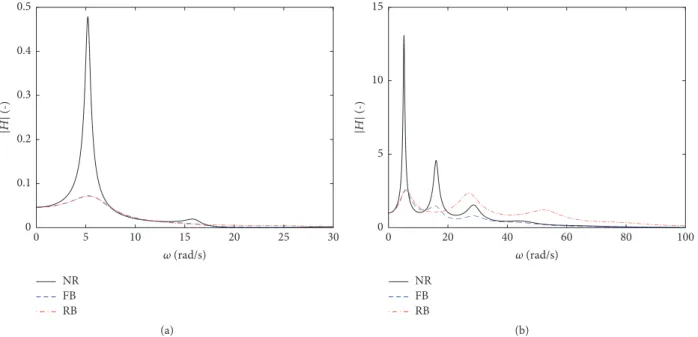
NR FB RB 5 10 15 20 25 30 0 (rad/s) 0 0.1 0.2 0.3 0.4 0.5 |H| (-) (a) NR FB RB 20 40 60 80 100 0 (rad/s) 0 5 10 15 |H| (-) (b)
Figure 4: FRFs of the NR, FB, and RB systems in terms of (a) top floor displacement; (b) top floor acceleration.
system, compared to the FB system, due to the different nature of the connection between the tower and the frame: viscous in the FB case and rigid in the RB one.
3.2. Frequency Response. This section analyzes the frequency
response of the NR frame and of the FB and RB
configura-tions corresponding to𝜅 = 1 and 𝜉add= 0.3. This analysis
provides a first insight into the modification of the dynamic response in terms of various EDPs of interest due to the retrofit. Figure 4 shows the absolute value of the top floor displacement and absolute acceleration Frequency Response Functions (FRFs).
With reference to the displacement, it can be seen that the response at the top of the NR frame is characterized by a very high peak at the fundamental circular frequency of vibration
of the system (2𝜋/𝑇1= 5.22 rad/s), as expected, whereas the
influence of higher order modes is negligible. Both the retrofit systems are effective in reducing the response peak, due to the added damping. The shift of the peak is low, because the retrofit systems do not alter significantly the first mode of vibration of the existing frame. The acceleration FRFs have a very different shape compared to the displacement FRFs. This is due to the high influence of the higher order modes, which contribute significantly to the top floor acceleration response, thus resulting in multiple peaks located in correspondence of the circular frequencies of the most relevant vibration modes of the systems, that is, modes 1, 2, and 3. Again, both the retrofit systems allow reducing the peak in correspondence of the first mode of vibration. Moreover, the peaks of the FRF for the FB system are observed in correspondence of the
same values of𝜔 of the frame, with the exception of the first
peak which is slightly shifted towards higher𝜔 values in the
retrofitted configuration. This is the result of the fact that the FB system does not alter significantly the dynamic response of the existing frame, by adding only damping and not stiffness.
On the other hand, the RB system presents a second and third peak in correspondence of higher frequency values compared to the FB and RB systems. This is the consequence of the stiffening effect of the tower, which modifies the period and shape of the higher modes of vibration of the existing frame. Figure 5 shows the FRF of the base shear of the frame and of the external bracings. It can be observed in Figure 5(a) that the second mode of vibration has a nonnegligible influence on the shear response of the frame, for all the analyzed arrangements. The RB system is more effective in reducing this EDP. On the other hand, the absolute values of the FRF of the external bracings base shear (Figure 5(b)) are always higher for the RB system than for the FB system. Thus, it is interesting to observe the changes of the total base shear due to the retrofit. This is plotted in Figure 6, showing that the addition of the retrofit system to the existing frame results in a reduction of the peak at the fundamental period. However, while the FB system reduces the response also at the other frequencies, the RB system amplifies the response around the value of the circular frequency of 28 rad/s (second mode).
3.3. Stochastic Seismic Response. This section reports and
compares the stochastic seismic responses of the NR frame
and of the FB and RB configurations corresponding to𝜅 = 1
and𝜉add= 0.3. In particular, Figure 7 shows and compares
the PSDs of the EDPs of interest for the different systems analyzed. These PSD are the results of the convolution between the FRFs, illustrated in Figures 4–6, and the PSD of the input, illustrated in Figure 3. It can be observed that the PSD of the input has a peak at the period of 0.5 s. Thus, some resonance effects with the first two modes of vibration of the systems considered are expected. In particular, it is observed in Figure 7 that while the PSD of the top displacement is dominated by the first mode (Figure 7(a)), the PSDs of the other response parameters have multiple peaks. Moreover, as
×104 10 20 30 40 50 60 0 (rad/s) 0 1 2 3 4 NR FB RB |H| (-) (a) FB RB 10 20 30 40 50 60 0 (rad/s) 0 1000 2000 3000 4000 5000 |H| (-) (b)
Figure 5: FRFs of the NR, FB, and RB systems in terms of (a) frame base shear; (b) external bracing base shear.
×104 NR FB RB 10 20 30 40 50 60 0 (rad/s) 0 1 2 3 4 |H| (-)
Figure 6: FRFs of the NR, FB, and RB systems in terms of total base shear.
in the case of the FRF, the peaks are located approximately in correspondence of the same frequencies in the case of the NR and FB configurations, while in the RB case only the first peak is close to the first peak of the other systems, as a result of the changes that the RB system induces through the added stiffness on the dynamic behaviour of the existing frame. The peak force that a damper has to withstand is an important response parameter, influencing the damper cost together with the damper stroke [37]. Figure 7(f) shows that the PSD of the sum of the damper forces is largely higher for the RB case than for the FB case. This is because the strokes of the dampers in the RB frame are reduced compared to those of the dampers in the FB configuration, and thus higher forces
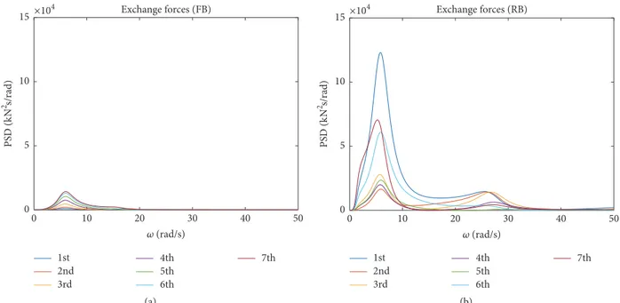
are required to obtain the same amount of energy dissipation. Obviously, the damper forces coincide with the interaction forces between the frame and the tower in the case of the FB configuration. The cost of the retrofit depends also on these mutual exchange forces between the existing and the external structures, whose PSDs are also plotted in Figures 8(a) and 8(b). It can be seen that the exchange forces are significantly higher for the RB case than for FB case. This is because in the RB case a rigid connection rather than a viscous one is used. The final part of the current section analyzes the peak values of the responses of interest for the different config-urations. Before discussing the results, the accuracy of the method of the peak factor is evaluated comparing the average
Top floor displacement ×10−4 NR FB RB 0 1 2 3 4 5 PS D ( G 2s/rad) 5 10 15 20 25 30 0 (rad/s) (a)
Top floor acceleration
NR FB RB 0 0.2 0.4 0.6 0.8 1 PS D ( G 2/M 3/rad) 10 20 30 40 50 0 (rad/s) (b) ×106 Frame base shear
NR FB RB 0 0.5 1 1.5 2 PS D ( E. 2s/rad) 10 20 30 40 50 0 (rad/s) (c)
External bracing base shear ×106 FB RB 0 0.5 1 1.5 2 PS D ( E. 2s/rad) 10 20 30 40 50 0 (rad/s) (d) ×106 Total base shear
NR FB RB 0 0.5 1 1.5 2 PS D ( E. 2s/rad) 10 20 30 40 50 0 (rad/s) (e)
Sum of damper forces ×106 FB RB 0 1 2 3 4 5 PS D ( E. 2s/rad) 10 20 30 40 50 0 (rad/s) (f)
Exchange forces (FB) 1st 4th 5th 6th 7th 2nd 3rd ×104 0 10 20 30 40 50 (rad/s) 0 5 10 15 PS D ( E. 2 s/rad) (a) Exchange forces (RB) 1st 4th 5th 6th 7th 2nd 3rd ×104 0 10 20 30 40 50 (rad/s) 0 5 10 15 PS D ( E. 2s/rad) (b)
Figure 8: PSD of the exchange forces for the FB (a) and RB (b) configurations.
MCS Peak factor 0.25 0.50 0.75 1 0 Displacements 0 1 2 3 4 5 6 7 L ev el (-) (a) MCS Peak factor 0.25 0.50 0.75 1 0 Interstorey drift 0 1 2 3 4 5 6 7 L ev el (-) (b) MCS Peak factor 0 1 2 3 4 5 6 7 L ev el (-) 0.25 0.50 0.75 1 0 Absolute accelerations (c) MCS Peak factor 0 1 2 3 4 5 6 7 L ev el (-) 0.25 0.50 0.75 1 0 Frame shear (d)
Figure 9: Comparison of the response parameters of interest for the NR configuration obtained through the peak factor estimation and through MCS approach.
peak responses of the NR case obtained with𝐸[𝜂𝑝] estimated
via (14) against the mean of the maxima resulting from a Monte Carlo Simulation (MCS) approach based on the frequency analysis of the system under 500 of sample seismic inputs.
Figure 9 shows the distribution of the floor displacements, interstorey drifts, absolute accelerations, and shear actions of the NR configuration according to MCS and to the peak fac-tor method. Each response parameter is normalized to have the estimate through the peak factor method equal to one. In particular, Figure 9(a) shows the displacements distribution along the height of the building, which presents a maximum value at the top. The interstorey drifts (IDRs) distribution, reported in Figure 9(b), is not regular and the maximum is attained in correspondence of the third storey. Figure 9(c) shows the absolute accelerations at the different floors, which have S-shaped distribution, highly influenced by higher order
modes, even though the maximum value is observed at the top. Finally, Figure 9(d) illustrates the shear actions resisted by the frame. Using the peak factor results in general in an overestimation of the maxima, with relative errors between 3.7% and 8.2% for all the EDPs of interest. The same technique applied to the analysis of the two retrofit configurations (FB and RB) also leads to a general underestimation of the max-ima, but with a maximum relative error lower than 3%. Given the high accuracy of the obtained estimates, the response val-ues reported hereinafter are those obtained via the peak factor method, which is computationally more efficient than MCS.
Figure 10 illustrates and compares the performances of the NR, FB, and RB configurations in terms of peak EDPs values estimated via the peak factor method. For each EDP considered, the peak values are normalized so that they are equal to unit in the NR case. This allows highlighting the benefits of the retrofit in terms of response reduction.
NR FB RB 0 0.25 0.50 0.75 1 Displacements 0 1 2 3 4 5 6 7 L ev el (-) (a) NR FB RB 0 0.25 0.50 0.75 1 Interstorey drift 0 1 2 3 4 5 6 7 L ev el (-) (b) NR FB RB 0 0.25 0.50 0.75 1 Absolute accelerations 0 1 2 3 4 5 6 7 L ev el (-) (c) NR FB RB 0.25 0.50 0.75 1 0 Frame shear 0 1 2 3 4 5 6 7 L ev el (-) (d) FB RB 0 0.25 0.5 0.75 1
External bracing shear 0 1 2 3 4 5 6 7 L ev el (-) (e) Total shear NR FB RB 0 0.25 0.5 0.75 1 0 1 2 3 4 5 6 7 L ev el (-) (f)
Figure 10: Comparison of the seismic performance of the NR, FB, and RB configurations in terms of parameters of interest.
Figure 10(a) illustrates the floor displacements distribution along the height of the building. It can be seen that the deformed shape of the existing frame remains the same after the retrofit in the FB case, whereas it is modified and linearized in the RB case. The relative reduction of the top floor displacements is nearly 61% for both the FB and RB configurations. The reduction values are similar for the two systems because the displacements are controlled by the first mode response, and the added damping ratio for this mode is nearly the same. The drift demand regularization in the case of the RB system can be better visualized in Figure 10(b), showing the interstorey drifts (IDRs) responses. The IDRs are lower in the RB system than in the FB system at the lower storeys and higher at the last two storeys.
Figure 10(c) shows the values of the floor absolute accelerations observed at the various levels of the building for the configurations investigated. The shape of the floor accelerations is not significantly modified after the retrofit, and both the FB and the RB configurations induce a reduction of the maximum absolute acceleration values with respect to the bare frame (NR). A better result in terms of maximum
acceleration reduction is achieved with the FB system. This system allows a maximum reduction of the accelerations of 48% in correspondence of the last floor, while the rocking tower provides a maximum reduction of 36%. This result is of particular importance for the performance evaluation of acceleration-sensitive nonstructural components and may impair the benefits of the retrofit with the rocking system.
As already discussed for the displacements, the addition of the two external dissipative systems results in a reduction of the base shear demand in the frame; in the FB case the reduction is equal to 59%, whereas in the RB case it is equal to 61% (Figure 10(d)). In general, the reduction is different from storey to storey in the FB configuration, with higher reduction at the higher storeys, while it is nearly the same at the various storeys in the RB configuration. The RB configuration also provides a more regular distribution of the shear at the different storeys compared to the other configurations. Figure 10(e) shows the values of the shear action resisted by the external structures of the retrofit configurations, normalized with respect to the frame shear of the bare building. The RB case results in higher values at
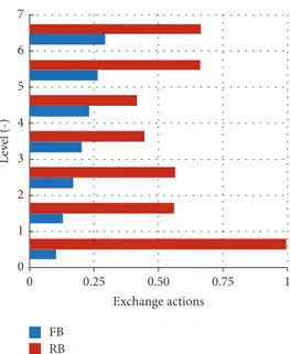
FB RB 0.25 0.50 0.75 1 0 Exchange actions 0 1 2 3 4 5 6 7 L ev el (-)
Figure 11: Exchange actions for the FB and RB configurations.
almost all the elevations, especially at lower storeys. Finally, Figure 10(f) illustrates the total storey shear. Again, the two retrofit systems exhibit similar performances in terms of base shear reduction, which is equal to 45% and 42%, respectively, in the FB and RB configurations.
Figure 11 illustrates the distribution of exchange actions for the two retrofit cases. In the FB system, where a damped connection system is used, these forces coincide with the internal axial actions in the FVDs, whose trend has already been discussed previously. In the RB configuration, the connection system is rigid, and the interaction forces are elastic and significantly higher than those of the FB case.
3.4. Parametric Study. In order to understand how the
stiffness and added damping of the external FB and RB frames influence the seismic performance of the coupled system, a parametric study is carried out by varying the
nondimen-sional parameters𝜅 and 𝜉add representing, respectively, the
external structures-to-existing frame stiffness and the added design damping ratio and by evaluating the corresponding changes in the seismic response. Three values of the
parame-ters𝜅 and 𝜉addare taken into account, that is,𝜅 = 0.25, 0.5, 1
and𝜉add= 0.1, 0.2, 0.3.
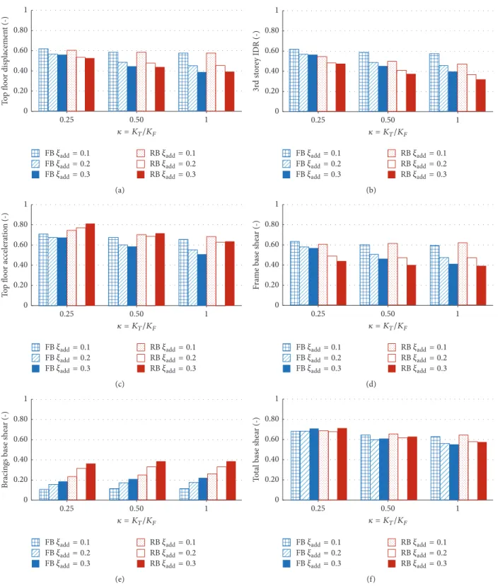
Figure 12 shows the results obtained for the two retrofit configurations in terms of the following monitored EDPs: the top floor displacement and absolute acceleration, the third floor interstorey-drift, the base shear of the frame and of the external structure, and the total base shear. The results are normalized such that the EDP values are unit in the case of the NR frame. With regard to the top floor displacement response (Figure 12(a)), it can be observed in general that both the FB and RB cases yield similar results, with a relative reduction between 38% and 61% in the FB system and a reduction between 40% and 61% in the RB system, with respect to the NR case. Higher values of the added damping result in a higher reduction of the displacement demand, as expected.
Although the best performance is achieved for𝜅 = 1 and 𝜉add
= 0.3 in both the configurations, a good response reduction
is obtained also for𝜅 = 0.5 and 𝜉add= 0.3, while for𝜅 = 0.25
the external structure is too flexible to resist the motion of the
existing structure and activate the dampers. In fact, if𝜉addis
low, the external structure does not need to be very stiff to
activate the dampers. On the other hand, if𝜉addis high, a stiff
external frame is required for the dampers to be effective. Figure 12(b) shows the third floor interstorey drifts for the different configurations and parameter combinations. The relative reduction achieved is in the range of 38% to 60% in the FB configuration, and in the range of 45%–68% in the RB configuration. As already observed for the displacements, the
best result are achieved for𝜅 = 1 and 𝜉add= 0.3, and the case
𝜅 = 0.25 is characterized by a reduced efficiency with respect to the other ones.
Figure 12(c) shows the results in terms of top floor absolute acceleration. The FB case provides the best result for
any combination of𝜅 and 𝜉add. The relative reduction of this
EDP for this case is between 28% and 48%, while it is between 18% and 37% in the RB case. Increasing the damping results in a reduction of the accelerations in the FB case but can increase
the accelerations in the RB case for some values of𝜅 and 𝜉add.
In fact, in the RB configuration the highest value of𝜉addyields
also the highest acceleration demand for both𝜅 = 0.25 and 𝜅
= 0.5, and this could affect the effectiveness of such retrofit scheme, when the protection of acceleration-sensitive
com-ponents is a design objective. For𝜅 = 1, similar acceleration
reductions are achieved for𝜉add= 0.2 and𝜉add= 0.3.
Figures 12(d)–12(f) describe the response in terms of frame base shear, external bracing base shear, and total base shear. Figure 12(d) shows that the relative reduction of the frame base shear is between 37% and 59% in the FB case, and between 38% and 61% in the RB case. Moreover, in the RB case the frame base shear reduction is not significantly
0 0.20 0.40 0.60 0.80 1 T o p flo o r disp lacemen t (-) 0.50 1 0.25 = KT/KF FB;>>= 0.1 FB;>>= 0.2 FB;>>= 0.3 RB;>>= 0.1 RB;>>= 0.2 RB;>>= 0.3 (a) 0 0.20 0.40 0.60 0.80 1 3r d st o re y ID R (-) 0.50 1 0.25 = KT/KF FB;>>= 0.1 FB;>>= 0.2 FB;>>= 0.3 RB;>>= 0.1 RB;>>= 0.2 RB;>>= 0.3 (b) 0 0.20 0.40 0.60 0.80 1 T o p flo o r accelera tio n (-) 0.50 1 0.25 = KT/KF FB;>>= 0.1 FB;>>= 0.2 FB;>>= 0.3 RB;>>= 0.1 RB;>>= 0.2 RB;>>= 0.3 (c) 0 0.20 0.40 0.60 0.80 1 F ra m e bas e she ar (-) 0.50 1 0.25 = KT/KF FB;>>= 0.1 FB;>>= 0.2 FB;>>= 0.3 RB;>>= 0.1 RB;>>= 0.2 RB;>>= 0.3 (d) 0 0.20 0.40 0.60 0.80 1 B racin gs bas e she ar (-) 0.50 1 0.25 = KT/KF FB;>>= 0.1 FB;>>= 0.2 FB;>>= 0.3 RB;>>= 0.1 RB;>>= 0.2 RB;>>= 0.3 (e) 0 0.20 0.40 0.60 0.80 1 T o ta l bas e she ar (-) 0.50 1 0.25 = KT/KF FB;>>= 0.1 FB;>>= 0.2 FB;>>= 0.3 RB;>>= 0.1 RB;>>= 0.2 RB;>>= 0.3 (f)
Figure 12: Results of the parametric analysis for the FB and RB configurations in terms of different EDPs of interest.
values. On the other hand, the retrofit effectiveness of the FB configuration reduces significantly by considering external
frames with𝜅 = 0.25 rather than 𝜅 = 0.5 or 𝜅 = 1. Figure 12(e)
describes the base shear resisted by the external structures. This parameter is more sensible to the added damping rather
than to the stiffness ratio. Generally, higher values of𝜅 and
𝜉add result in higher values of the bracing base shear. The
values of the base shear of the external structures normalized with respect to that of the bare frame are comprised between 11% and 22% in the FB case, while they are between 23% and 39% in the RB case. Finally, from Figure 12(f) it is evident that the total base shear reduction provided by the FB and RB case is nearly the same, no matter what values of the stiffness ratio or of the added damping are considered, with a relative
0 0.20 0.40 0.60 0.80 1 Ex ch an ge ac tio n (-) 0.25 0.50 1 = KT/KF FB;>>= 0.1 FB;>>= 0.2 FB;>>= 0.3 RB;>>= 0.1 RB;>>= 0.2 RB;>>= 0.3 (a) 0 0.20 0.40 0.60 0.80 1 FVD axial ac ti o n (-) 0.25 0.50 1 = KT/KF FB;>>= 0.1 FB;>>= 0.2 FB;>>= 0.3 RB;>>= 0.1 RB;>>= 0.2 RB;>>= 0.3 (b)
Figure 13: Results of the parametric analysis for the FB and RB configurations in terms of (a) exchange forces between one external frame and the existing frame and (b) sum of the forces of the FVDs.
reduction of the shear resisted by the bare frame between 32% and 45% for the FB configuration and between 29% and 42% for the RB case, with respect to the NR frame.
Figure 13(a) illustrates the values of the maximum exchange forces between the external frames and the existing structure. In the case of the FB configuration, these corre-spond to the exchange forces at the top floor, whereas in the RB configuration these correspond to the exchange forces at the first floor (see Figure 11). The values for the different
com-binations of𝜅 and 𝜉addare normalized so that the exchange
forces in the case of𝜅 = 1 and 𝜉add= 0.1 are equal to unit in the
RB configuration, which is in general characterized by higher values compared to the FB configuration. It can be observed
that, in the FB system, increasing𝜅 does not affect
signifi-cantly the force demand, whereas increasing𝜉add yields an
increase of forces. On the other hand, in the RB configuration,
increasing𝜅 results in an increase of forces, and increasing
𝜉addreduces the forces for𝜅 = 0.5 and 𝜅 = 1. Figure 13(b) shows
the maximum values of the sum of the damper forces for the two retrofit configurations. In general, these forces increase
by increasing𝜉add, whereas they do not increase significantly
by increasing𝜅. Higher values are observed in the RB system
for all the combination𝜅 − 𝜉addanalyzed.
4. Conclusions
In this paper, two alternative arrangements of external passive retrofitting systems are analyzed, each one characterized by a different kinematic behaviour. The former (FB con-figuration) consists of an external fixed base steel braced frame connected to the existing one by means of dampers placed horizontally at the floor levels. The latter system (RB configuration) is an innovative one, based on coupling the building with a “dissipative tower,” which is a steel braced frame, hinged at the foundation level, and activating the dampers through its rocking motion. The two systems are nonclassically damped and the analysis of the performance under the uncertain earthquake input is carried out by
means of a general formulation involving stochastic dynamics concepts, which allows efficiently estimating the peak values of the responses of interest and thus carrying out parametric studies for different values of the stiffness and added damping of the external structures. In particular, the FB and RB retrofit configurations are synthetically described by the parameter 𝜅, measuring the ratio between the global stiffness of the external frames to that of the existing frame, and by the
external frames design added damping ratio𝜉add.
First, the case corresponding to 𝜅 = 1 and 𝜉add = 0.3
is analyzed in detail. The results show that the two retrofit configurations are characterized by similar performances in terms of reduction of the top displacement, interstorey drifts and total shear demand with respect to the nonretrofitted (NR) case. The RB system yields the best distribution of interstorey drifts, due to a linearization of the displacements distribution. On the other hand, this solution is characterized by higher external bracing shear actions and higher absolute floor accelerations, with respect to the FB system. The peak values of the internal actions are lower in the FB system, thanks to the viscous interconnection which does not induce significant changes in the modal shapes of the existing frame. The forces exchanged between the external bracings and the existing frame at the links placed at storey levels are significantly higher in the RB case with respect to forces observed in the interconnecting dampers in the FB case.
In the following part of the paper, a parametric analysis
is carried out by considering different values of𝜅 and 𝜉addfor
the two retrofitting systems and observing the changes in the response parameters usually considered in design practice.
The cases corresponding to𝜅 = 0.5 and 𝜅 = 1 provide nearly the
same performance in terms of the response parameters con-sidered, with the exception of the exchange forces in the RB configuration, which increase significantly by passing from 𝜅 = 0.5 to 𝜅 = 1. This result has significant cost implications,
because lower𝜅 values correspond to smaller steel profiles.
The FB system provides the best performance in terms of reduction of absolute accelerations of the top floor compared
to the RB system for all the nondimensional parameter combinations. Moreover, the top floor absolute acceleration generally increases by increasing the added damping in the RB case. The total base shear in the two retrofit configurations
is nearly the same for all the values of𝜅 and 𝜉addconsidered.
The existing frame base shear and the external bracings shear,
respectively, decrease and increase by increasing𝜉add, while
they are less sensitive to variations of 𝜅. Finally the RB
configuration provides always higher values of both exchange forces and axial actions in the FVDs, with respect to the FB
case, for all the values of𝜅 and 𝜉addconsidered.
Conflicts of Interest
The authors declare that there are no conflicts of interest regarding the publication of this paper.
Acknowledgments
The study reported in this paper was partially supported by the Italian Department of Civil Protection within the Reluis-DPC Projects 2017. The authors gratefully acknowledge this financial support.
References
[1] M. D. Symans and M. C. Constantinou, “Passive fluid viscous damping systems for seismic energy dissipation,” ISET Journal of Earthquake Technology, vol. 35, no. 4, pp. 185–206, 1998. [2] C. Christopoulos and A. Filiatrault, Principles of Passive
Supple-mental Damping and Seismic Isolation, IUSS Press, Pavia, Italy, 2006.
[3] L. Ragni, L. Dezi, A. Dall’Asta, and G. Leoni, “HDR devices for the seismic protection of frame structures: Experimental results and numerical simulations,” Earthquake Engineering & Structural Dynamics, vol. 38, no. 10, pp. 1199–1217, 2009. [4] J. K. Whittle, M. S. Williams, T. L. Karavasilis, and A.
Blake-borough, “A comparison of viscous damper placement methods for improving seismic building design,” Journal of Earthquake Engineering, vol. 16, no. 4, pp. 540–560, 2012.
[5] A. Di Cesare, F. C. Ponzo, D. Nigro, M. Dolce, and C. Moroni, “Experimental and numerical behaviour of hysteretic and visco-recentring energy dissipating bracing systems,” Bulletin of Earthquake Engineering, vol. 10, no. 5, pp. 1585–1607, 2012. [6] J.-S. Hwang, W.-C. Lin, and N.-J. Wu, “Comparison of
distri-bution methods for viscous damping coefficients to buildings,” Structure and Infrastructure Engineering, vol. 9, no. 1, pp. 28–41, 2013.
[7] O. Lavan and M. Avishur, “Seismic behavior of viscously damped yielding frames under structural and damping uncer-tainties,” Bulletin of Earthquake Engineering, vol. 11, no. 6, pp. 2309–2332, 2013.
[8] A. Dall’asta, E. Tubaldi, and L. Ragni, “Influence of the nonlin-ear behavior of viscous dampers on the seismic demand haz-ard of building frames,” Earthquake Engineering & Structural Dynamics, vol. 45, no. 1, pp. 149–169, 2016.
[9] A. Dall’Asta, F. Scozzese, L. Ragni, and E. Tubaldi, “Effect of the damper property variability on the seismic reliability of linear systems equipped with viscous dampers,” Bulletin of Earthquake Engineering, vol. 15, no. 11, pp. 5025–5053, 2017.
[10] F. Freddi, E. Tubaldi, L. Ragni, and A. Dall’Asta, “Probabilistic performance assessment of low-ductility reinforced concrete frames retrofitted with dissipative braces,” Earthquake Engineer-ing & Structural Dynamics, vol. 42, no. 7, pp. 993–1011, 2013. [11] C. Passoni, A. Belleri, A. Marini, and P. Riva, “Existing
struc-tures connected with dampers: state of the art and future developments,” in Proceedings of the 2nd European Conference on Earthquake Engineering and Seismology, pp. 25–29, Istanbul, Turkey, 2014.
[12] T. Trombetti and S. Silvestri, “Novel schemes for inserting seismic dampers in shear-type systems based upon the mass proportional component of the Rayleigh damping matrix,” Journal of Sound and Vibration, vol. 302, no. 3, pp. 486–526, 2007.
[13] O. Lavan and D. Abecassis, “Seismic behavior and design of wall–EDD–frame systems,” Frontiers in Built Environment, vol. 1, 2015.
[14] Z. Yang, Y. L. Xu, and X. L. Lu, “Experimental seismic study of adjacent buildings with fluid dampers,” Journal of Structural Engineering, vol. 129, no. 2, pp. 197–205, 2003.
[15] V. Gattulli, F. Potenza, and M. Lepidi, “Damping performance of two simple oscillators coupled by a visco-elastic connection,” Journal of Sound and Vibration, vol. 332, no. 26, pp. 6934–6948, 2013.
[16] E. Tubaldi, M. Barbato, and A. Dall’Asta, “Performance-based seismic risk assessment for buildings equipped with linear and nonlinear viscous dampers,” Engineering Structures, vol. 78, pp. 90–99, 2014.
[17] E. Tubaldi, M. Barbato, and A. Dall’Asta, “Efficient approach for the reliability-based design of linear damping devices for seismic protection of buildings,” ASCE-ASME Journal of Risk and Uncertainty in Engineering Systems, Part A: Civil Engineer-ing, Special Issue on Stochastic Dynamics and Reliability Analysis of Structural and Mechanical Systems Subject to Environmental Excitations, vol. 2, no. 2, 2016.
[18] E. Tubaldi, “Dynamic behavior of adjacent buildings connected by linear viscous/viscoelastic dampers,” Structural Control and Health Monitoring, 2015.
[19] L. Gioiella, E. Tubaldi, F. Gara, and A. Dall’Asta, “Modal prop-erties and seismic response of existing building retrofitted by external bracings with viscous dampers,” in Proceedings of the 7th European Congress on Computational Methods in Applied Sciences and Engineering, ECCOMAS Congress 2016, pp. 5156– 5171, Crete Island, Greece, June 2016.
[20] N. Makris and M. Aghagholizadeh, “The dynamics of an elastic structure coupled with a rocking wall,” Earthquake Engineering & Structural Dynamics, vol. 46, no. 6, pp. 945–962, 2017. [21] Z. Qu, A. Wada, S. Motoyui, H. Sakata, and S. Kishiki,
“Pin-supported walls for enhancing the seismic performance of building structures,” Earthquake Engineering & Structural Dynamics, vol. 41, no. 14, pp. 2075–2091, 2012.
[22] D. Wu and X. L. Lu, “Structural performance evaluation of a new energy-dissipation and light-weight rocking frame by numeri-cal analysis and experiment,” in Proceedings of the 10th Pacific Conference on Earthquake Engineering Building and Earth-quake-Resilient, Sidney, Australia, November 2015.
[23] D. Roia, F. Gara, A. Balducci, and L. Dezi, “Dynamic tests on an existing r.c. school building retrofitted with “dissipative towers”,” in Proceedings of the 11th International Conference on Vibration Problems, Lisbon, Portugal, September 2013. [24] D. Roia, F. Gara, A. Balducci, and L. Dezi, “Ambient vibration
retrofitting works with external steel “dissipative towers”,” in Proceedings of the 9th International Conference on Structural Dynamics, EURODYN 2014, pp. 2509–2516, Porto, Portugal, July 2014.
[25] A. Balducci, Dissipative Towers. Application n. EP2010074723820100831, WO2010EP62748 20100831, Interna-tional and European classification E04H9/02 – Italian conces-sion n 0001395591, 2005.
[26] J. Blume, “Holiday Inn,” in San Fernando Earthquake of Febru-ary 9, 1971, vol. I, part A, chapter 29, U.S. Department of Commerce, National Oceanic and Atmospheric Administra-tion, Washington, DC, USA, 1973.
[27] K. A. Porter, J. L. Beck, and R. V. Shaikhutdinov, “Investigation of sensitivity of building loss estimates to major uncertain variables for the Van Nuys testbed,” PEER Report 2002/2003 4, College of Engineering, University of California, 2002. [28] H. Krawinkler, “Van Nuys Hotel building testbed report:
exer-cising seismic performance assessment,” PEER Report 2005/ 2011, Department of Civil and Environmental Engineering, Stanford University, October 2005.
[29] L. D. Lutes and S. Sarkani, Random vibrations: Analysis of Struc-tural and Mechanical Systems, Elsevier Butterworth-Heine-mann, Burlington, 2004.
[30] A. Preumont, Twelve Lectures on Structural Dynamics, vol. 198, Springer, 2013.
[31] R. W. Clough, J. Penzien, and D. S. Griffin Computers and Struc-tures Inc., Berkeley, 2003.
[32] L. Gioiella, E. Tubaldi, F. Gara, L. Dezi, and A. Dall’Asta, “Anal-ysis and comparison of two different configurations of external dissipative systems,” in Proceedings of the 10th International Conference on Structural Dynamics, EURODYN 2017, pp. 164– 169, September 2017.
[33] A. D. Kiureghian and A. Neuenhofer, “Response spectrum method for multi-support seismic excitations,” Earthquake Engineering & Structural Dynamics, vol. 21, no. 8, pp. 713–740, 1992.
[34] E. Tubaldi, M. Barbato, and S. Ghazizadeh, “A probabilis-tic performance-based risk assessment approach for seismic pounding with efficient application to linear systems,” Structural Safety, vol. 36-37, pp. 14–22, 2012.
[35] M. Shinozuka and G. Deodatis, “Simulation of stochastic pro-cesses by spectral representation,” Applied Mechanics Reviews, vol. 44, no. 4, pp. 191–204, 1991.
[36] ASCE Standard ASCE/SEI 41-13, Seismic Evaluation and Retrofit of Existing Buildings, American Society of Civil Engineers, Reston, VA, USA, 2014.
[37] D. Altieri, E. Tubaldi, M. de Angelis, E. Patelli, and A. Dall’Asta, “Reliability-based optimal design of nonlinear viscous dampers for the seismic protection of structural systems,” Bulletin of Earthquake Engineering, pp. 1–20, 2017.
International Journal of
Aerospace
Engineering
Hindawi www.hindawi.com Volume 2018Robotics
Journal of Hindawi www.hindawi.com Volume 2018 Hindawi www.hindawi.com Volume 2018Active and Passive Electronic Components VLSI Design Hindawi www.hindawi.com Volume 2018 Hindawi www.hindawi.com Volume 2018
Shock and Vibration
Hindawi
www.hindawi.com Volume 2018
Civil Engineering
Advances inAcoustics and VibrationAdvances in
Hindawi
www.hindawi.com Volume 2018
Hindawi
www.hindawi.com Volume 2018
Electrical and Computer Engineering Journal of Advances in OptoElectronics Hindawi www.hindawi.com Volume 2018
Hindawi Publishing Corporation
http://www.hindawi.com Volume 2013 Hindawi www.hindawi.com
The Scientific
World Journal
Volume 2018 Control Science and Engineering Journal of Hindawi www.hindawi.com Volume 2018 Hindawi www.hindawi.com Journal ofEngineering
Volume 2018Sensors
Journal of Hindawi www.hindawi.com Volume 2018 Machinery Hindawi www.hindawi.com Volume 2018 Modelling & Simulation in Engineering Hindawi www.hindawi.com Volume 2018 Hindawi www.hindawi.com Volume 2018 Chemical EngineeringInternational Journal of Antennas and
Propagation International Journal of Hindawi www.hindawi.com Volume 2018 Hindawi www.hindawi.com Volume 2018 Navigation and Observation International Journal of Hindawi www.hindawi.com Volume 2018