Titolo
Relazione Programmatica sul Simulatore
Ente emittente
CIRTEN
PAGINA DI GUARDIA
Descrittori
Tipologia del documento:
Rapporto Tecnico
Collocazione contrattuale:
Accordo di programma ENEA-MSE: tema di ricerca "Nuovo
nucleare da fissione"
Argomenti trattati:
Sommario
Reattori nucleari evolutivi
Reattori nucleari ad acqua
Controllo dei reattori nucleari
Il documento descrive il software sviluppato dal Politecnico di Milano per un simulatore di impianto che sia in grado di affrontare problematiche di controllo e gestione di reattori nucleari. La caratteristiche chiave di tale simulatore sono:
• modularità, l'intero sistema reattore è costruito connettendo i modelli dei singoli componenti, che sono indipendenti dale diverse condizioni al contomo;
• accessibilità, ogni componente è facilmente identificabile e modificabile da utenti esperti; • efficienza, la velocità di calcolo è elevata;
• affidabilità, il software è testato ed è disponibile ampia documentazione.
Per raggiungere questi obiettivi, come base per lo sviluppo del simulatore è stato utilizzato il linguaggio Modelica. Questo linguaggio è il risultato dei recenti sviluppi nel campo della modellistica "object oriented" per multi-fisica e dinamica del sistema. Esso ha il vantaggio di essere open-source ed è già stato utilizzato in diversi campi industriali.
Il caso test per l'applicazione di questo approccio "objected-oriented" è stato il reattore nucleare di tipo integrale IRIS
Note
REPORT PAR 2007 LP5.B - CERSE-POLIMI RL 114512010
Autori: A. Cammi
Politecnico di Milano, Dipartimento di Energia, Sezione Ingegneria Nucleare-CeSNEF
Copia n. In carico a:
2
NOMEFIRMA
1
NOMEFIRMA
o
EMISSIONE~"tl
1C3, ~Q~
f-F-IR-M
NOMEA-f---+-
NA--+
xr
I~.+--
l'/)
--'
Monti
'1
-
ntl'JA
-
I
-
t---I
NAPER LA
R
ICERCAT
ECNOLOGICAN
UCLEAREPOLITECNICO
DI
MILANO
DIPARTIMENTO DI ENERGIA, Sezione INGEGNERIA NUCLEARE-CeSNEF
Relazione programmatica sul simulatore
Antonio Cammi
CERSE-POLIMI RL-1145/2010
Milano, Settembre 2010
LP5.B3 - 2 - CERSE-POLIMI RL-1145/2010
INDEX
E
XECUTIVES
UMMARY... ‐ 3 ‐
1
I
NTRODUCTION... ‐ 4 ‐
2
MODELICA
‐
O
BJECT‐O
RIENTED LANGUAGE FOR SYSTEM AND PLANT SIMULATION... ‐ 6 ‐
3
L
IBRARY STRATEGY:
“T
HERMOP
OWER”
COMPONENTS AND MODELS... ‐ 7 ‐
4
“NUKOMP”
LIBRARY:
COMPONENTS AND MODELS... ‐ 11 ‐
4.1
Pressurizer Model ... - 11 -
4.2
Point Kinetics Neutronic Model ... - 12 -
4.3
Fuel Model ... - 13 -
5
IRIS
S
IMULATOR:
COMPARISON WITHRELAP
CODE RESULTS... ‐ 14 ‐
5.1
Plant Dynamics – Steam Generator Feed Water Flow Rate Step reduction (20%) ... - 16 -
5.2
Plant Dynamics – Control Rod Step Insertion and Withdrawal (20%, +5%) ... - 18 -
5.3
Plant Dynamics – Turbine Admission Valve Step opening (20%, +10%) ... - 20 -
6
C
ONCLUSIONS... ‐ 22 ‐
LP5.B3 - 3 - CERSE-POLIMI RL-1145/2010
E
XECUTIVES
UMMARYThis document presents the development of an adequate modeling and simulation tool for Dynamics and Control. The key features of the developed simulator are: “Modularity” - the system model is built by connecting the models of its components, which are written independently of their boundary conditions; “Openness” - the code of each component model is clearly readable and close to the original equations and easily customized by the experienced user; “Efficiency” - the simulation code is fast; “Tool support” - the simulation tool is based on reliable, tested and well-documented software.
To achieve these objectives, the Modelica language was used as a basis for the development of the simulator. The Modelica language is the result of recent advances in the field of object-oriented, multi-physics, dynamic system modelling. The language definition is open-source and it has already been successfully adopted in several industrial fields.
The test bed for the application of the object-oriented approach has been the new generation, integral type, IRIS nuclear reactor. To provide the required capabilities for the analysis, specific models for the nuclear reactor components have been developed, to be applied for the dynamic simulation of the IRIS integral reactor, albeit keeping general validity for PWR plants. The following Modelica models have been written to satisfy the IRIS modelling requirements and are presented in this work: point reactor kinetic, fuel heat transfer, control rods model, and a once-through type steam generator, thus obtaining a specific library of nuclear models and components. As far as other classical power generation plant components are concerned, the ThermoPower open library, developed at Politecnico di Milano as well, has been adopted and is briefly presented in the report. Originally conceived for conventional, fossil-fired plants, the highly modular approach allowed to effectively re-use the models of the balance of plant systems, which have been connected to the models of the nuclear power generation process, to obtain a system simulator for the IRIS reactor.
LP5.B3 - 4 - CERSE-POLIMI RL-1145/2010
1 I
NTRODUCTIONAcademic education and operational training of engineers and power plant operators is essential for their acquiring the necessary knowledge, skills and qualification for designing and operating a nuclear power plants, and for effective feedback of real life experience including human based operating errors. To develop, assess, monitor and improve functional competence of nuclear engineers and nuclear power plant staff, it is essential to use adequate simulation tools, assessment methods and training support and management tools working in close relation and warranting quality and traceability.
As a statement of general validity, the key features for an optimal reactor system simulator appear to be: “Modularity” - the system model should be built by connecting the models of its components, which have to be written independently of their boundary conditions; “Openness” - the code of each component model should be clearly readable, close to the original equations and easily customised by the experienced user; “Efficiency” - the simulation code should be fast running; “Tool support” - the simulation tool should be based on reliable, accurate, tested and well-documented software.
Few simulation environments and tools fulfilling all the above mentioned characteristics seem to be currently available for nuclear applications. Recent advances in the field of object-oriented, multi-physics, dynamic system modelling led to the definition of the Modelica language, representing a viable path to achieve the above-mentioned goals. The language definition is open-source and it has already been successfully adopted in different fields, such as automotive, robotics, thermo-hydraulic and mechatronic systems.
In this frame, specific models for nuclear reactor components have been developed, to be applied for the dynamic simulation of the IRIS integral reactor albeit keeping general validity for PWR plants. The reactor pressure vessel houses not only the nuclear fuel, control rods and control rods drive mechanisms, and support structures, but also all the major reactor coolant system components including the coolant pumps, the steam generators and the pressurizer, as depicted in Fig. 1.
LP5.B3 - 5 - CERSE-POLIMI RL-1145/2010 Fig. 1. IRIS reactor view and main components (arrows show primary fluid path).
Steam generator (Cioncolini et al., 2003) and pressurizer (Popov and Yoder, 2008) components, together with the internal control rod drive mechanism (Conway et al., 2004), represent innovative features with respect to current PWRs, thus requiring a further effort in terms of modelling. In particular: i) the steam generators are of once-through type, framed into modules and made up by helical coil tube bundles 30 m long, with the secondary two phase mixture generated inside the tubes and flowing upward, while the primary flow rate is in downward crossflow on the external side; ii) the pressurizer is placed into the reactor pressure vessel, therefore it represents a large volume of saturated steam and saturated or subcooled liquid, with a non regular geometry and without sprays as one of the pressure control systems; iii) the internal control rod drive mechanism (ICRDM) considered for this study has been the hydraulically driven type (Ricotti et al., 2003), with an external pump system supplying the required flow rate and pressure to sustain the hydraulic piston, to which the control rods are linked, and with a set of valves needed to temporarily modify the equilibrium pressure, thus allowing the withdrawal and insertion steps. Notwithstanding the IRIS design has recently moved towards a different technological solution, i.e. an ICRDM based on electro-magnetic motors and devices, the models library includes also this type of component, the adoption of which is foreseen in other integral type reactor designs (Xiaotian and Shuyan, 2006; Fukami and Santecchia, 2000).
Besides the inherent distinctive design characteristics of the main components, other features affect the dynamic response of the reactor and significantly differ from current plants: the large water inventory of the integral reactor is three times that of an equivalent PWR of the same power, resulting in an increased thermal inertia of the primary fluid; the large volumes of the primary side, mainly the riser and the downcomer, lead to a wide characteristic period for the primary circuit transit time, one order of magnitude bigger than current plants; on the other hand, the once-through type steam generators allow a quick response of the component on the secondary side, because of the reduced secondary fluid inventory and thermal inertia.
LP5.B3 - 6 - CERSE-POLIMI RL-1145/2010 As a consequence of the above mentioned considerations, a dynamic simulator of an innovative, integral reactor has been set up, in order to study the dynamic response of IRIS, by adopting the Modelica object-oriented language. The primary and secondary systems of the reactor have been simulated, by assembling component models already available in a specific thermal-hydraulic library and suitable nuclear component models developed for this specific purpose. Both the language and the models are described in the following sections, with preliminary results of test transients reported as well.
2 MODELICA
-
O
BJECT-O
RIENTED LANGUAGE FOR SYSTEM AND PLANTSIMULATION
The Modelica language (Mattsson et al., 1998; Modelica Association web site, 2007; Fritzson, 2004) was first introduced in 1997, as the product of an international cooperative effort toward the definition of an object-oriented language for the modelling of general physical models, described by algebraic and differential equations. The key features of the language are briefly summarised.
A-causal modelling. The equations of each model are written independently of the actual boundary conditions, without
deciding a-priori which are the inputs and which are the outputs. The causality of the model is determined automatically by the Modelica model interpreter or compiler at the aggregate level, when a system model is assembled out of elementary ones. In this way, models are much easier to write, document, and reuse, while the burden of determining the actual sequence of computations required for the simulation is entirely left to the compiler.
Code transparency. Equations written in Modelica models tightly match the way they are written on report, so that it is
very easy to understand what's inside a given model, as well as to modify or enhance it.
Encapsulation. The models of a system components are connected through rigorously defined interfaces or
“connectors” corresponding to the physical interaction with the outside whole. For example: electrical connectors carry a voltage and a current, thermal connectors carry a temperature and a heat flow, and so on. As long as two different components have compatible connectors, they can be bound together, regardless of their inner details. This feature is essential for the development of libraries of re-usable models; moreover, it allows to easily replace a part of a system model with a more detailed or a more simplified one, without affecting the rest of the model.
Inheritance. Model libraries can be given a hierarchical structure, in which more complex models are obtained from
basic models by adding specific variables, equations or even models. For example, it is possible to write the equations describing the flow of a generic gas in a tube; the model of the flow of a particular, e.g. a multi-component ideal gas mixture, can be obtained by inheriting from the general one and by adding the specific model of the ideal gas.
Multi-physics modelling. The Modelica language is general in scope, as it provides modelling primitives such as generic
algebraic, differential and difference equations, and is not tied to any specific engineering domain, such as mechanics, electrical engineering, or thermodynamics. It is then quite straightforward to model systems having a multi-disciplinary nature, such as mechatronic systems, resulting from the interaction of mechanical, electrical and control sub-systems, or nuclear plants, resulting from the interaction of thermo-hydraulic, nuclear and control sub-systems.
Reusability. A-causal modelling and encapsulation are a strong incentive towards the development of libraries of
LP5.B3 - 7 - CERSE-POLIMI RL-1145/2010 in the definition of the Modelica language, while others are being developed for more specific domains, either as open-source or as proprietary codes.
The Modelica language has already been applied to a wide range of system modelling problems in different engineering domains, as demonstrated by the topics in the annual international conference specifically devoted to it (Otter, 2002; Fritzson, 2003; Schmitz, 2005; Kral, 2006).
When developing a new application using Modelica, it is often the case that some, or most, of the needed models are already available in some previously developed library, so that it is possible to concentrate the effort on the writing of the fewer models which are not already available. In the case of the project illustrated in this work, it has been possible to develop the model of a complete nuclear power plant by only writing the models of the nuclear power generation processes, and then connecting them to taken from the ThermoPower library (Casella and Leva, 2003, 2006), which was not originally conceived to deal with nuclear power plants.
As to the efficiency of the actual simulation code obtained from a complex Modelica model, one may wonder whether the possibility of describing the process with a high-level modelling language has to be paid in terms of increased computational burden. It turns out that this is usually not the case: Modelica compilers incorporate sophisticated symbolic manipulation algorithms, which allow, among other things, to obtain index-1 systems of differential-algebraic equations from higher-index ones, to symbolically solve both linear and non-linear model equations, and to find efficient calculation sequences through sorting and automatic tearing of system equations; the resulting code is then linked to state-of-the-art numerical integration codes such as DASSL (Brenan et al., 1989). All of this process is completely transparent to the user, and the resulting efficiency is often comparable, or even higher, than that of laboriously hand-crafted Fortran, C or Matlab code, which is error-prone and hard to document and reuse.
Finally, it is worth noting that the definition of the Modelica language, owned by the non-profit Modelica Organisation, is in the public domain, so it is not tied to any specific simulation tool vendor. As of today, there are two commercial tools supporting this language: Dymola (2008), which was used in this project, and MathModelica (2008). An open-source tool, OpenModelica (2008), has been under development for several years, and is expected to be usable for industrial-strength projects in a few years. Other simulation tool vendors, such as LMS-Imagine and ITI, are currently developing Modelica-compatible front-ends for their tools. It is therefore expected that good support for this language will be available and improved in the long term.
3 L
IBRARY STRATEGY:
“T
HERMOP
OWER”
COMPONENTS AND MODELSThe complete model of the IRIS reactor has been built using models from two different libraries: ThermoPower and NUKOMP.
The ThermoPower library has been developed as an open-source library for the modelling of thermal power plants at the system level, to support the design and validation of control systems. The library has been developed according to the following guidelines:
a) models are derived from first principle equations whenever possible, e.g. mass, momentum, and energy dynamic balance equations, or from acknowledged empirical correlations;
b) the level of detail of the models is flexible, up to the maximum fidelity which is compatible with a system-level simulation, e.g. ruling out complex models with 3-dimensional CFD;
LP5.B3 - 8 - CERSE-POLIMI RL-1145/2010 c) the structure of the model interfaces is as simple as possible and is independent of the modelling assumptions inside each model (lumped-parameter vs. distributed-parameter model, one-phase vs. two-phase flow, homogeneous vs. non-homogeneous flow, inertial effects accounted for or neglected, etc.), so that models of specific parts of the process can be effortlessly replaced with more accurate or more simplified counterparts;
d) the library is structured with a limited use of the inheritance mechanism, so that the code of a particular physical component is not scattered through many different classes; in this way, it is straightforward to understand the equations of a specific model by just looking in a single place in the code;
e) the library is an open-source software and available on the Web (ThermoPower Home Page, 2008).
As for the simulator of the IRIS integral reactor, several ThermoPower models have been used without modification. Their modelling principles are summarised here; for further details, the reader is referred to (Casella and Leva, 2003, 2006), as well as to the online documentation in (ThermoPower Home Page 2008). As an example, the detailed equations and the corresponding Modelica code given in the solving system Eq.(1) and Fig. 2 refer to the header, a thermalhydraulic basic component corresponding to a control volume in the best estimate system codes. This gives a flavour of the way models are formulated in an object-oriented context.
The model of the fluid flow in a cylindrical conduit is based on the dynamic mass, energy, and momentum conservation equations, which are originally given as one-dimensional, partial differential equations. Since Modelica can only describe systems of ordinary differential-algebraic equations, the original distributed-parameter model is first discretised by using either the finite-volume method (Casella, 2006), or a Petrov-Galerkin finite-element method (Schiavo and Casella, 2007). The model is formulated in order to correctly handle possible flow reversal conditions. A homogeneous model, i.e. same velocity for the liquid and vapour phases, is adopted for two-phase flow conditions. The heat transfer coefficients are computed using Dittus-Boelter's and Chen's correlations.
The fluid flow model is used both for the primary side, i.e. the core coolant loop, and for the secondary side, i.e. the once-through steam generators.
The heat transfer model computes the actual heat flow between two 1-dimensional interacting objects, usually a fluid and a metal wall. The heat transfer coefficient can be assumed either as constant, or supplied by the fluid flow model. A cylindrical metal wall is modelled by a simplified 1-dimensional version of Fourier's equations: the thermal resistance is computed according to the formulation of Fourier's equation in cylindrical coordinates, while the heat capacity terms are lumped in the middle of the tube thickness. This model is used to represent the steam generator pipe walls.
A turbulent, lumped pressure drop model is assumed, proportional to the kinetic pressure.
Other specific models refer to typical power plant components. As an example, the coolant pump model is based on the characteristic curves of the centrifugal pumps, the first relating head, flow rate and shaft speed, the second to compute the mechanical power consumption; the thermal effects of the pump on the fluid are thus correctly represented.
The header is modelled as a rigid plenum filled with water exchanging heat, with a metal wall having a finite thermal capacitance. If the pressure P and the specific enthalpy h of the fluid and the wall temperature Tm are chosen as the state
variables, it is possible to write the mass, energy and momentum balances for the fluid and the energy balance for the metal wall as:
LP5.B3 - 9 - CERSE-POLIMI RL-1145/2010
gH
P
P
P
P
T
T
S
dt
dT
C
T
T
S
h
w
h
w
dt
dh
h
h
dt
dP
P
h
V
w
w
dt
dh
h
dt
dP
P
V
i o o m m m m o o i i o i
1
(1)where is the fluid density, P is the fluid pressure, wi and wo are the inlet and outlet flow rates (assumed positive when
entering), Pi and Po the corresponding pressures, hi and ho the corresponding specific enthalpies, T is the fluid
temperature, Cm is the metal wall thermal capacity, is the fluid-metal heat transfer coefficient, S is the fluid-metal
interface area, H the height of the inlet over the outlet.
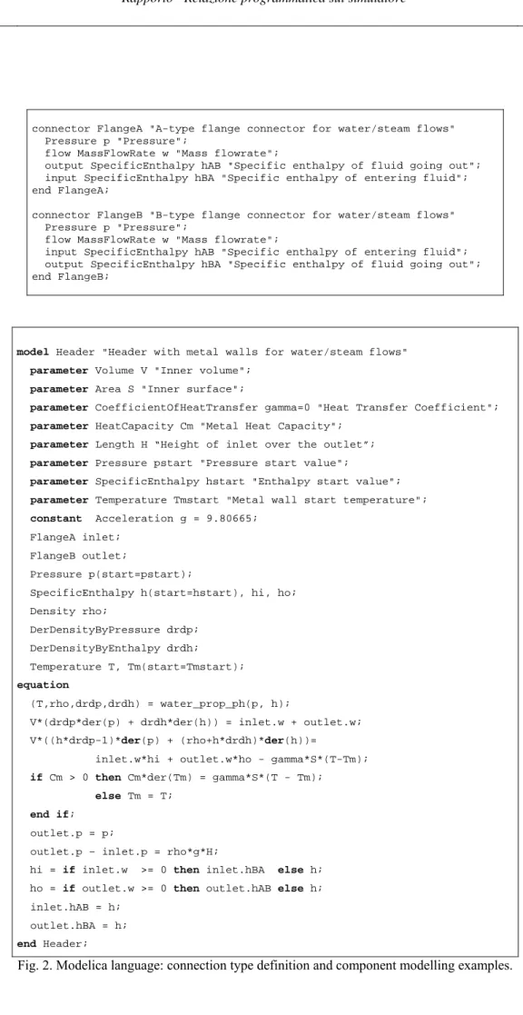
The model is connected to the outside world through two connectors of type referred as “FlangeA” and “FlangeB”, having the Modelica code definition as reported in Fig. 2.
When an A-type connector is bound to a B-type connector, connection equations are generated automatically: the sum of the flow variables is zero while the remaining variables having the same name are equalled to each other.
The Modelica corresponding to Eq. (1) can be written as shown in Fig. 2.
The actual code is slightly more complex, in order to provide features such as a replaceable fluid model, whose description is however beyond the scope of this work.
As mentioned above, two important features are worth stressing again: the model code tightly resembles the way equations are written on report, and the model equations are written using the boundary conditions provided by the two connectors, without introducing artificial causality, and without bothering how the specific model equations, coupled with the outside world equations, will be actually solved by the final simulation code.
LP5.B3 - 10 - CERSE-POLIMI RL-1145/2010
connector FlangeA "A-type flange connector for water/steam flows" Pressure p "Pressure";
flow MassFlowRate w "Mass flowrate";
output SpecificEnthalpy hAB "Specific enthalpy of fluid going out"; input SpecificEnthalpy hBA "Specific enthalpy of entering fluid"; end FlangeA;
connector FlangeB "B-type flange connector for water/steam flows" Pressure p "Pressure";
flow MassFlowRate w "Mass flowrate";
input SpecificEnthalpy hAB "Specific enthalpy of entering fluid"; output SpecificEnthalpy hBA "Specific enthalpy of fluid going out"; end FlangeB;
model Header "Header with metal walls for water/steam flows"
parameter Volume V "Inner volume"; parameter Area S "Inner surface";
parameter CoefficientOfHeatTransfer gamma=0 "Heat Transfer Coefficient";
parameter HeatCapacity Cm "Metal Heat Capacity"; parameter Length H “Height of inlet over the outlet”;
parameter Pressure pstart "Pressure start value";
parameter SpecificEnthalpy hstart "Enthalpy start value";
parameter Temperature Tmstart "Metal wall start temperature"; constant Acceleration g = 9.80665;
FlangeA inlet; FlangeB outlet;
Pressure p(start=pstart);
SpecificEnthalpy h(start=hstart), hi, ho; Density rho; DerDensityByPressure drdp; DerDensityByEnthalpy drdh; Temperature T, Tm(start=Tmstart); equation (T,rho,drdp,drdh) = water_prop_ph(p, h);
V*(drdp*der(p) + drdh*der(h)) = inlet.w + outlet.w; V*((h*drdp-1)*der(p) + (rho+h*drdh)*der(h))=
inlet.w*hi + outlet.w*ho - gamma*S*(T-Tm); if Cm > 0 then Cm*der(Tm) = gamma*S*(T - Tm); else Tm = T;
end if; outlet.p = p;
outlet.p – inlet.p = rho*g*H;
hi = if inlet.w >= 0 then inlet.hBA else h; ho = if outlet.w >= 0 then outlet.hAB else h;
inlet.hAB = h; outlet.hBA = h;
end Header;
LP5.B3 - 11 - CERSE-POLIMI RL-1145/2010
4 “NUKOMP”
LIBRARY:
COMPONENTS AND MODELSThe models available in the ThermoPower library allowed a fast assembling of the largest part of the reactor primary and secondary systems. The remaining components, i.e. the pressurizer, the reactor core and the hydraulically driven ICRDM, have been ad-hoc simulated by writing suitable models, derived from elaborating open literature (Todreas and Kazimi, 2001) or previous works (Brega et al., 1996; Vitulo, 2003), thus leading to a first release of the NUKOMP library of Nuclear Components and Models, specific for nuclear reactor components.
The pressurizer model has been written by considering a separate phases approach. The core has been simulated by assembling a neutron kinetics model and a thermal model for the fuel. The nuclear component models are briefly described in the following paragraphs.
4.1 Pressurizer Model
The physical model is based on a non-equilibrium, two regions formulation of the fluid balance equations with a control volume approach, as shown in Fig.3. The two regions are supposed to be isobaric and singularly isothermal, and will be referred to as liquid zone and vapour zone, respectively. The mathematical model is a system of coupled, nonlinear equations in five primary unknowns, namely the liquid zone mass (Ml) and the vapour zone mass (Mv), the
corresponding enthalpies (hl and hv) and the system pressure (pv). The solving system refers to the mass and energy
balance equations for the liquid zone (Eq.2 and 3, respectively) and the vapour zone (Eqs.4 and 5), plus a congruence equation on the control volume, as in Eq.6.
saf l rel l eva spr cnd sl l t d M d , , (2)
t d p d V W W W h h h h h h h M t d d v l wall l bh prh l saf l l rel l sat v eva sat l spr sat l cnd sl sl l l , , , , , , (3) saf v rel v cnd eva v t d M d , , (4)
t d p d V W h h h h h h h M t d d v v wall v spr sat l spr v saf v v rel v sat l cnd sat v eva v v , , , , , , (5) v v l l M M V (6)where the variables are: M for mass, h for specific enthalpy, p for pressure, for mass flow rate, W for thermal power,
V for volume, for density, t for time, while the following subscripts hold: l for liquid, v for vapour, sat for saturation
condition, sl for surge line, cnd for condensation, eva for evaporation, spr for sprays (note that albeit spray and relief valves are not included in the simulation presented in this work, the pressurizer model was developed to be generically applicable to PWRs), rel for relief valves, saf for safety valves, prh for proportional heaters, bh for backup heaters, wall for pressurizer wall heat losses. The closure equations needed are the evaporation and condensation flow rates, as reads
LP5.B3 - 12 - CERSE-POLIMI RL-1145/2010 in Eq.7 where eva and cnd are the bubble rising time and the droplet falling time, and the state equations (Eq.8), as
obtained from the IAPWS IF97 water properties correlations (Wagner, W., et al. 2000):
cnd
vsat lsat
v sat v v cnd sat l sat v eva sat l l l eva h h h h M h h h h M , , , , , , ; (7)
v lv
lv v
sat v l f p gh p h, ;, ,, (8)Fig
.
3. Conceptual scheme for a typical pressurizer component.4.2 Point Kinetics Neutronic Model
The neutronic power generated into the fuel is proportional to the neutronic population n, which responds to the point reactor kinetics balance equations (Eq.9 and 10):
6 1 i ici n dt dn (9) 6 ,..., 1 n c i dt dc i i i i (10)where c is the precursor concentration leading to a delayed neutron source, is the total reactivity of the core, is the fraction of delayed neutrons, is the decay constant of the precursors and is the mean neutron generation time. The model set up for the NUKOMP library is able to treat enriched uranium, plutonium or thorium-based fuels.
LP5.B3 - 13 - CERSE-POLIMI RL-1145/2010 Reactivity feedbacks are taken into account as well, by considering linear or non linear feedback coefficients, for the coolant density effect (c), the fuel Doppler effect (f), the effect of the boron concentration (B) into the primary fluid
as a neutronic poison and the level of insertion of the control rod banks into the core (CR).
These relations are reported in Eq.11:
0 0 0 1 1 C C v v T T B B c c c c eff eff f f B c f CR (11)where Teff and Teff0 are the instantaneous and reference effective fuel temperature, respectively, obtained from the fuel
model described in the next paragraph, vc and
v
c0are the instantaneous and reference specific volumes of the coolant, Cand C0 are the instantaneous and reference boric acid concentration in the coolant. The reference values are those
corresponding to the nominal, full power operation of the reactor.
4.3 Fuel Model
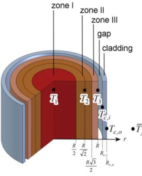
The time dependent Fourier equation in one dimensional cylindrical geometry is applied to the three fuel rod zones: pellet, gap and cladding. The main assumption of the model is to consider only the radial heat transfer, thus disregarding both the axial and the circumferential diffusions.
For the pellet, gap and cladding the corresponding balance equations read:
q r T k r r r t T cpp p p p p , 1 (12) 0 r T k r r g g (13) r T k r r r t T cpc c c c c , 1 (14)
where is the density, cp is the specific heat, T is the temperature, k is the thermal conductivity, q is the volumetric
source term, r is the radial dimension and t the time, while the subscripts stand for: p, the pellet, g, the gap, c, the cladding. Note that the heat capacity of the gap region has been neglected in this model.
The heat transfer model is represented in Fig.4, with the pellet discretized into three zones of equal volume. Eqs.12 to 14, together with the conditions of heat flux vanishing at the pellet centre and the continuity of the temperatures and heat fluxes at the three boundaries pellet-gap-cladding-coolant allow the determination of Tp( tr, ), Tc( tr, ) and Tg( tr, ).
In particular, the condition at the cladding-coolant interface reads:
Rco m
o Rc r c H T T r T k , , (15)LP5.B3 - 14 - CERSE-POLIMI RL-1145/2010 in which the rhs of Eq.15 refers to the coolant mean values into the core, i.e. H is the convective heat transfer coefficient and
T
m is the mean water temperature over the entire core height L:L dz z T T L m m
0 ( ) (16)The coolant temperature profile Tm(z) is obtained from the solution of the thermal-hydraulic model. In addition to the
above equations, five correlations synthesising the dependences of cp,p,cp,c,kp,kc as a function of the temperature
and
k
g as a function of both the reactor power and the burn-up have been adopted.The effective fuel temperature, used to evaluate the Doppler feedback contribution on neutronics, is defined as follows:
R r r
eff T T
T 49 059 (17)
Fig. 4. Fuel pellet radial scheme for heat transfer modelling.
5 IRIS
S
IMULATOR:
COMPARISON WITHRELAP
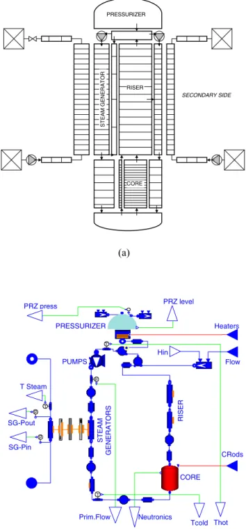
CODE RESULTSA Modelica-based simulator has been obtained by assembling the required components from ThermoPower and NUKOMP libraries, as shown in Fig.5. Both the primary and the secondary systems of the IRIS integral reactor have been simulated, the boundary conditions for the reactor being the steam generator feed water flow rate, temperature and pressure and the condenser pressure on the secondary side, and the control rod banks level of insertion into the core on the primary side.
LP5.B3 - 15 - CERSE-POLIMI RL-1145/2010 CORE RISER PRESSURIZER SECONDARY SIDE S T E A M GE NERA T O R (a) T T T p p F CORE PUMPS ST EAM G E N E RATORS PRESSURIZER R ISER CRods Neutronics Tcold Thot Prim.Flow SG-Pin SG-Pout T Steam PRZ level PRZ press Heaters Flow Hin
Fig. 5. RELAP nodalization scheme (a) and Modelica simulator (b) for the IRIS reactor.
The simulator has been validated against the well established, best estimate code RELAP, based on more complex and detailed thermal-hydraulic models. Moreover, a comparison with a simulator SIMULINK-based, which represents one of the most popular and widely adopted tool for dynamic simulation and control, has been carried out as well. The results are encouraging: the computational time required for the transient computation of 2000 seconds transient is
LP5.B3 - 16 - CERSE-POLIMI RL-1145/2010 reduced by a factor about 300 (from about seven hours to less than one minute) with the Modelica model; the effort required to implement the same component models and the whole plant simulator is roughly one order of magnitude lower for the Modelica model than the SIMULINK model, roughly equivalent to some man-months in the latter case. As far as the accuracy of the results is concerned, the same degree of accuracy has been obtained by both simulators, with better results for the Modelica model when transients with stiff parameters or boundary conditions are to be simulated.
As part of this validation process, a set of open-loop transients has been analysed for the IRIS plant, namely the responses of the reactor to instantaneous step variation of i) the Feed Water flow rate, ii) the Control Rods position and iii) the Turbine Admission Valve opening. Note that at this stage of the investigation, the interest was more on the simulator performance and benchmark with different models than on the accurate and realistic analysis of various operating sequences.
During the transients, no plant controls are in operation and the pressure in the primary side is kept to constant. At the beginning of the transient, all the neutronic and thermal-hydraulic parameters are at values corresponding to the plant nominal, full power, steady-state operating conditions. A first comparison between the Modelica simulator and the RELAP code has been performed on the steady state, nominal conditions for the reactor. Table 1 summarizes the main data, showing a good agreement both between the codes and with respect to the design data for the IRIS reactor. The mismatch in the primary flow rate is due to the different correlations for water/steam properties used in Modelica and RELAP.
Parameter IRIS design data RELAP model data MODELICA model data Thermal Power MW 1000 999.998 1000.000
Primary Flow Rate kg/s 4500 4512.120 4588.752
Core Inlet Temp. K 565.15 565.181 565.402
Core Outlet Fluid Temp. K 603.15 603.082 602.716
Secondary Flow Rate kg/s 502.8 502.801 502.800
Steam Temperature K 590.15 590.893 590.993
Secondary Pressure bar 58 58.004 58.007
Table 1
Main IRIS reactor design data at full power, nominal operating conditions, and corresponding values obtained by the RELAP code and the Modelica simulator.
5.1 Plant Dynamics – Steam Generator Feed Water Flow Rate Step reduction (20%)
The first event considered to benchmark the Modelica simulator to the RELAP5 mod3.2 plant model (Grgic et al., 2003) has been a step reduction in the steam generator feedwater flow rate by 20%. During the transient the control rod system was assumed not available, thus the core neutronics response depends only on the neutronic feedbacks. The expected plant response in these conditions is that following the reduction in feedwater flow, the heat removal rate from
LP5.B3 - 17 - CERSE-POLIMI RL-1145/2010 the steam generators will decrease and the reactor coolant system temperature will increase as more heat is generated in the system than is removed by the steam generators. Due to the core negative feedback, the power of the reactor will decrease until a new equilibrium condition is reached at a lower power level.
The results reported in Fig. 6 and 7 show an excellent agreement between the Modelica simulator and the detailed RELAP plant model.
0 200 400 600 800 time [s] 8.00x10⁸ 8.40x10⁸ 8.80x10⁸ 9.20x10⁸ 9.60x10⁸ 1.00x10⁹ 1.04x10⁹ T herm al P ow er [W ] RELAP MODELICA
Transient: FeedWater Step (-20% nominal mass flow rate)
0 200 400 600 800 time [s] RELAP MODELICA -0.04 -0.03 -0.02 -0.01 0 0.01 R eact iv it y [ $]
Transient: FeedWater Step (-20% nominal mass flow rate)
0 200 400 600 800
time [s]
MODELICA - Tout Core
RELAP - Tout Core
MODELICA - Tin Core RELAP - Tin Core 560 570 580 590 600 610 P ri m ar y Fl ui d Te m pe ra tur e [ K ]
Transient: FeedWater Step (-20% nominal mass flow rate)
0 200 400 600 800 time [s] RELAP MODELICA 4440 4480 4520 4560 4600 Pr im ar y F low R at e [ kg/ s]
Transient: FeedWater Step (-20% nominal mass flow rate)
Fig. 6. Modelica vs. RELAP comparison – Core Thermal Power, Core Reactivity, Primary Temperature and Primary Flow Rate for the Feed Water flow rate step reduction (20%) transient.
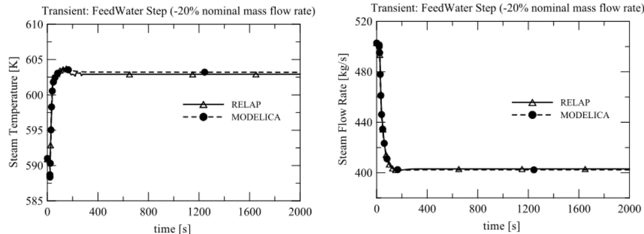
0 400 800 1200 1600 2000 time [s] RELAP MODELICA 585 590 595 600 605 610 Stea m Tempe ra tu re [ K ]
Transient: FeedWater Step (-20% nominal mass flow rate)
0 400 800 1200 1600 2000 time [s] RELAP MODELICA 400 440 480 520 St ea m Fl ow R at e [kg/ s]
Transient: FeedWater Step (-20% nominal mass flow rate)
Fig. 7. Modelica vs. RELAP comparison – Steam Generator Steam Temperature and Feed Water Flow Rate for the FW flow rate step reduction (20%) transient.
LP5.B3 - 18 - CERSE-POLIMI RL-1145/2010 During the transient the core inlet temperature increases by 6 K and the core outlet temperature decreases from 603.1 K to 602.6 K. The final equilibrium power at the end of the simulation is a function of the feedback coefficients: the more negative the doppler and moderator density coefficients, the power will be more reduced. In the presented simulation the neutronic feedback coefficients have been assumed equal to 8.86 pcm/kg m-3 for the mean coolant
density and to –3 pcm/°C for the effective fuel temperature. Note that to allow a meaningful comparison the RELAP model was modified to adopt the same core feedback model of the Modelica simulator, since the RELAP model is devoted to safety analysis, not to operational-like transient analysis.
In this simulation, at the end of the transient after about 800 s when the overall reactivity is again at zero, the thermal power decreased from the nominal value of about 1 GW down to 0.827 GW, with a 17.3% reduction.
On the secondary side, the decrease of the feed flow rate leads to a decrease of the steam pressure, from the nominal value of 58 bar to 48 bar. The superheated steam temperature is instead increased from 591 K to 603 K.
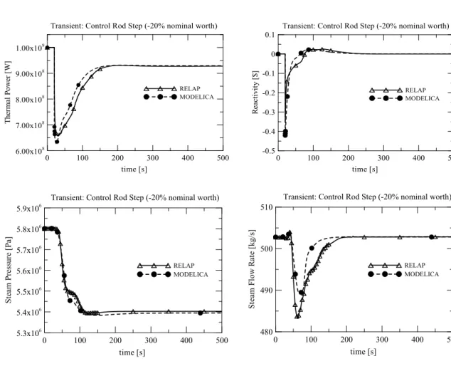
5.2 Plant Dynamics – Control Rod Step Insertion and Withdrawal (20%, +5%)
The second event considered for the benchmark has been a control rod step insertion by 20% of the nominal worth. During the transient the core neutronics response depends only on the neutronic feedbacks. The expected plant response in these conditions is that following the insertion of the control rod, the thermal power will decrease as well as the reactor temperatures (coolant and fuel); because of the core negative feedback, the power of the reactor will increase until a new equilibrium condition is reached at a lower power level. The results are reported in Fig. 8.
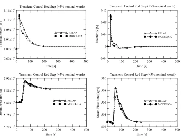
The results of control rod step withdrawal simulation (insertion of 5% of nominal control rod worth) are shown in Fig. 9.
The results reported in Fig. 8 and 9 show an excellent agreement between the Modelica simulator and the detailed RELAP plant model.
LP5.B3 - 19 - CERSE-POLIMI RL-1145/2010 0 100 200 300 400 500 time [s] 6.00x10⁸ 7.00x10⁸ 8.00x10⁸ 9.00x10⁸ 1.00x10⁹ The rm al P ow er [ W ] RELAP MODELICA
Transient: Control Rod Step (-20% nominal worth)
0 100 200 300 400 500 time [s] RELAP MODELICA -0.5 -0.4 -0.3 -0.2 -0.1 0 0.1 Re ac ti vi ty [ $]
Transient: Control Rod Step (-20% nominal worth)
0 100 200 300 400 500 time [s] RELAP MODELICA 5.3x10⁶ 5.4x10⁶ 5.5x10⁶ 5.6x10⁶ 5.7x10⁶ 5.8x10⁶ 5.9x10⁶ St ea m P ress ur e [ P a]
Transient: Control Rod Step (-20% nominal worth)
0 100 200 300 400 500 time [s] RELAP MODELICA 480 490 500 510 St ea m Fl ow R at e [k g/ s]
Transient: Control Rod Step (-20% nominal worth)
Fig. 8. Modelica vs. RELAP comparison – Core Thermal Power, Core Reactivity, Steam Generator Steam Pressure and Steam Flow Rate for the Control Rod step insertion (20%) transient.
LP5.B3 - 20 - CERSE-POLIMI RL-1145/2010 0 100 200 300 400 500 time [s] 9.60x10⁸ 1.00x10⁹ 1.04x10⁹ 1.08x10⁹ 1.12x10⁹ 1.16x10⁹ Th er mal Pow er [W] RELAP MODELICA
Transient: Control Rod Step (+5% nominal worth)
0 100 200 300 400 500 time [s] RELAP MODELICA -0.04 0 0.04 0.08 0.12 R ea cti vity [ $]
Transient: Control Rod Step (+5% nominal worth)
0 100 200 300 400 500 time [s] RELAP MODELICA 5.70x10⁶ 5.75x10⁶ 5.80x10⁶ 5.85x10⁶ 5.90x10⁶ St eam P ress ur e [ Pa ]
Transient: Control Rod Step (+5% nominal worth)
0 100 200 300 400 500 time [s] RELAP MODELICA 502 504 506 508 510 St ea m F low R at e [ kg/ s]
Transient: Control Rod Step (+5% nominal worth)
Fig. 9. Modelica vs. RELAP comparison – Core Thermal Power, Core Reactivity, Steam Generator Steam Pressure and Steam Flow Rate for the Control Rod step withdrawal (+5%) transient.
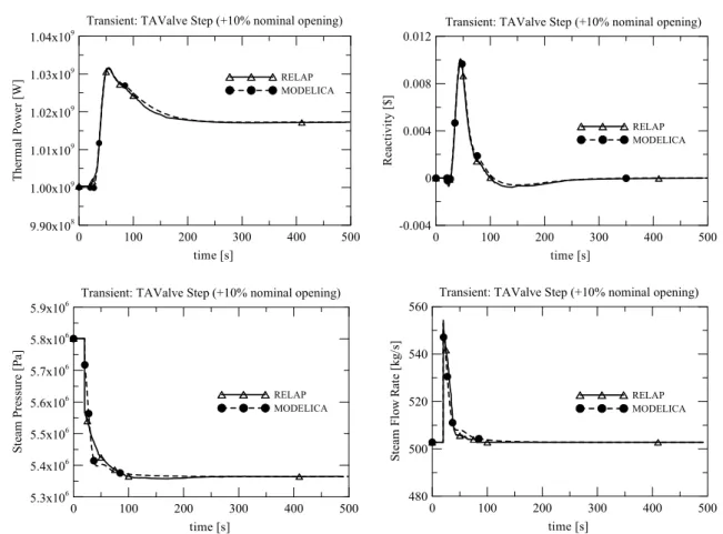
5.3 Plant Dynamics – Turbine Admission Valve Step opening (20%, +10%)
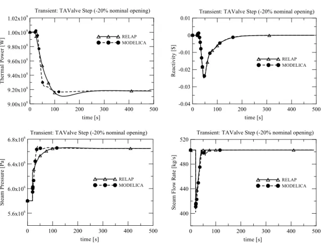
As a further example of transient analysis and comparison, useful to gain knowledge about the dynamic response of the reactor, a step opening (10% with respect to nominal value) and a step closing (-20% with respect to nominal value) of the Turbine Admission Valve has been simulated (Figs. 10, 11). The transient does not represent a real operational transient for the plant, since also in this case also the controls are supposed not to be in operation, but is a preliminary, valuable insight in order to identify the optimum strategy and configuration of the control system.
The step opening of the turbine valve allows the steam flow rate to follow with a sudden increase, due to the depressurization and corresponding flashing of the secondary fluid. The effect on the primary side is a slight overcooling, with a decrease of the coolant temperatures at core inlet (from 565.4 K to 564.6 K) while the core outlet temperature does not change (~ 601 K). The neutronic feedbacks push the core power to about 1.02 GW with an overall increase of 2 % with respect to the nominal value. The very mild response of the integral reactor is due to the limited inventory in the steam generators, that limits the amount of steam generated to the available feedwater flow into the steam generators (that is kept constant during the simulation), except for the very short spike shown in Fig. 11, where the results for the Turbine Admission Valve step closing (-20%) are reported.
LP5.B3 - 21 - CERSE-POLIMI RL-1145/2010 0 100 200 300 400 500 time [s] 9.90x10⁸ 1.00x10⁹ 1.01x10⁹ 1.02x10⁹ 1.03x10⁹ 1.04x10⁹ Th er ma l P ow er [W ] RELAP MODELICA
Transient: TAValve Step (+10% nominal opening)
0 100 200 300 400 500 time [s] RELAP MODELICA -0.004 0 0.004 0.008 0.012 R eac ti vi ty [ $]
Transient: TAValve Step (+10% nominal opening)
0 100 200 300 400 500 time [s] RELAP MODELICA 5.3x10⁶ 5.4x10⁶ 5.5x10⁶ 5.6x10⁶ 5.7x10⁶ 5.8x10⁶ 5.9x10⁶ St ea m P res su re [ P a]
Transient: TAValve Step (+10% nominal opening)
0 100 200 300 400 500 time [s] RELAP MODELICA 480 500 520 540 560 St ea m Fl ow R at e [ kg/ s]
Transient: TAValve Step (+10% nominal opening)
Fig. 10. Modelica vs. RELAP comparison – Core Thermal Power, Core Reactivity, Steam Generator Steam Pressure and Steam Flow Rate for the Turbine Admission Valve step opening (+10%) transient.
LP5.B3 - 22 - CERSE-POLIMI RL-1145/2010 0 100 200 300 400 500 time [s] 9.00x10⁸ 9.20x10⁸ 9.40x10⁸ 9.60x10⁸ 9.80x10⁸ 1.00x10⁹ 1.02x10⁹ The rm al Pow er [W ] RELAP MODELICA
Transient: TAValve Step (-20% nominal opening)
0 100 200 300 400 500 time [s] RELAP MODELICA -0.04 -0.03 -0.02 -0.01 0 0.01 R eact iv it y [ $]
Transient: TAValve Step (-20% nominal opening)
0 100 200 300 400 500 time [s] RELAP MODELICA 5.6x10⁶ 6.0x10⁶ 6.4x10⁶ 6.8x10⁶ St ea m P ress ur e [ P a]
Transient: TAValve Step (-20% nominal opening)
0 100 200 300 400 500 time [s] RELAP MODELICA 400 440 480 520 St ea m Fl ow R at e [k g/ s]
Transient: TAValve Step (-20% nominal opening)
Fig. 11. Modelica vs. RELAP comparison – Core Thermal Power, Core Reactivity, Steam Generator Steam Pressure and Steam Flow Rate for the Turbine Admission Valve step closure (20%) transient.
6 C
ONCLUSIONSThe development of a plant simulator with Modelica for control studies on integral reactors and for the IRIS reactor in particular has been presented in this report.
The development cycle of the simulator has been shortened dramatically compared to alternative approaches, due to the re-use of existing models and to the object-oriented approach to write the model code. Moreover, the system model can be easily modified to improve the modelling of the nuclear generation process, without affecting the remaining parts of the code.
The simulation time for one transient is reduced by almost three orders of magnitude, while keeping the fundamental dynamic behaviour of the plant. This makes the model usable for control system studies.
Finally, it is planned to further validate this model against experimental results obtained from scaled laboratory models of parts of the plant.
LP5.B3 - 23 - CERSE-POLIMI RL-1145/2010
7 REFERENCES
Brega, E., Lombardi, C., Ricotti, M.E., Sordi, R., 1996. Development and Initial Validation of Fast-Running Simulator of PWRs: TRAP-2, in: IAEA-TECDOC-872, 341-352, IAEA, Vienna.
Brenan, K.E., Campbell, S.L., Petzold, L.R., 1989. Numerical solution of initial-value problems in differential algebraic equations. North-Holland Ed.
Cammi, A., Casella, F., Ricotti, M. E., Schiavo, 2005b. Object-Oriented Modeling, Simulation and Control of the IRIS Nuclear Power Plant with Modelica. In Proceedings 4th International Modelica Conference, Hamburg, Germany, Mar. 7-8, pp. 423-432.
Carelli, M.D., Conway, L.E., Kling, C.L., Oriani, L., Petrovic, B., Lombardi, C.V., Ricotti, M.E., Barroso, A.C.O., Collado, J.M., Cinotti, L., Todreas, N.E., Grgic, D., Boroughs, R.D., Ninokata, H., Oriolo, F., 2005. Design and Safety of IRIS, an Integral Water Cooled SMR for Near Term Deployment, in: Kuznetsov, V., Innovative small and medium sized reactors: Design features, safety approaches and R&D trends. IAEA-TECDOC-1451, IAEA, Vienna, pp. 51-74.
Carelli, M.D., Conway, L.E., Oriani, L., Petrovic, B., Lombardi, C.V., Ricotti, M.E., Barroso, A.C.O., Collado, J.M., Cinotti, L., Todreas, N.E., Grgic, D., Moraes, M.M., Boroughs, R.D., Ninokata, H., Ingersoll, D.T., Oriolo, F., 2004. The Design and Safety Features of the IRIS Reactor. Nucl. Eng. & Des. vol. 230, pp. 151-167.
Carlson, K.E., Berta, V.T., Lenglade, C.E., Riemke, R.A., Lintner, M.A., Schultz, R.R., Fletcher, C.D., McKenzie, C.C., Shieh, A.S.-L., Jenkins, E.E., Mesina, G.L., Shumway, R.W., Johnsen, E.C., Miller, C.S., Slater, C.E. Johnsen, G.W. Mortensen, G.A., Sloan, S.M., Kelly, J.M., Murray, P.E., Warnick, M., Kuo, H-H., Nielson, R.B., Weaver, W.L., Larson, N.S., Paik, S., Wilson, G.E., 1990. RELAP5/MOD3 Code Manual. NUREG/CR-5535, INEL-95/0174, Vol. I–IV, Rev. 1.
Casella, F., 2006. Object-Oriented Modelling of Two-Phase Fluid Flows by the Finite Volume Method. In Proceedings 5th Mathmod Vienna, Austria, Sep. 6-8, pp. 631-640.
Casella, F., Leva, A., 2003. Modelica open library for power plant simulation: design and experimental validation, in: Proceedings of Modelica Conference 2003, Linköping, Sweden, Nov. 3-4, pp.41-50.
http://www.modelica.org/Conference2003/papers/h08_Leva.pdf.
Casella, F., Leva, A., 2006. Modelling of Thermo-Hydraulic Power Generation Processes Using Modelica. Mathematical and Computer Modeling of Dynamical Systems, vol. 12, n. 1, pp. 19-33.
LP5.B3 - 24 - CERSE-POLIMI RL-1145/2010 Cioncolini, A., Cammi, A., Cinotti, L., Castelli, G., Lombardi, C., Luzzi, L., Ricotti, M.E., 2003. Thermal Hydraulic
Analysis of Iris Reactor Coiled Tube Steam Generator, in: ANS Topical Meeting in Mathematics & Computations (M&C), April 6-10, Gatlinburg, TN, USA.
Conway, L.E., Petrovic, B., Kanagawa, T., Ricotti, M.E., 2004. Internal Control Rod Drive Mechanism, Design Options for IRIS, in: Proceedings of ICAPP’04, paper 4315, Pittsburgh, June 13-17.
Dymola, 2008. Dymola User’s Manual. Dynasym AB.
Fritzson, P. (Ed.), 2003. Proceedings of the 2003 Modelica Conference, Linköping, Sweden, Nov. 3-4. http://www.modelica.org/events/Conference2003.
Fritzson, P., 2004. Principles of Object-Oriented Modeling and Simulation with Modelica 2.1, Wiley-IEEE Press. Fukami, M.V.I., Santecchia, A., 2000. CAREM Project: Innovative Small PWR. Progress Nucl. En., 37 (1-4), 265-270. Grgic, D., Bajs, T., Oriani, L., 2003. Development of RELAP5 Nodalization for IRIS Non-LOCA Transient Analyses,
in: Proceedings of ANS Topical Meeting in Mathematics & Computations, Gatlinburg, USA, April 6-10.
Kral, C. (Ed.), 2006. Proceedings of the 2006 Modelica Conference, Vienna, Austria, Sep. 4-5. http://www.modelica.org/events/modelica2006/Proceedings/
Lerchl, G., Austregesilo, H., 1995. The ATHLET Code Documentation Package. User's Manual, GRS-P-1 / Vol.1. Liles, D.R., Mahassi, J.H., 1986. TRAC-PF1/MOD1: An Advanced Best Estimate Computer Program For Pressurised
Water Reactor Thermal Analysis. NUREG/CR-3858.
MathModelica, 2008. MathModelica User’s Manual. Mathcore Engineering AB.
Mattsson, S.E., Elmqvist, H., Otter, M., 1998. Physical system modeling with Modelica. Control Engineering Practice, 6, 501-510.
Micaelli, J.C., Bestion, D., Bernard, M., Porracchia, A., Miraucourt, J.M., Catalani, L., 1988. CATHARE. Best estimate thermalhydraulic code for reactor safety studies, Last developments. Proceedings of the International ENS/ANS Conference on Thermal Reactor Safety, Avignon, October 2-7
Modelica Association web site, 2007. http://www.modelica.org/.
OpenModelica, 2008. Open Modelica Project, http://www.ida.liu.se/labs/pelab/modelica/Open Modelica.html
Otter M. (Ed.), 2002. Proceedings of the 2002 Modelica Conference, Oberpfaffenhofen, Germany, March, 18-19. http://www.modelica.org/Conference2002/papers.shtml.
LP5.B3 - 25 - CERSE-POLIMI RL-1145/2010 Ricotti, M.E., Cammi, A., Carelli, M., Colombo, E., Lombardi, C., Passoni, M., Rizzo, C., 2003, Hydraulically Driven Control Rod Concept for Integral Reactors: Fluid Dynamic Simulation and Preliminary Test, in: Proceedings of GENES4/ANP2003, paper 1028, Kyoto, Sept. 15-19.
Schiavo, F., Casella, F., 2007. Object-Oriented modelling and simulation of heat exchangers with finite element methods. Mathematical and Computer Modelling of Dynamical Systems. 13, 3, 211-235.
Schmitz, G. (Ed.), 2005. Proceedings of the 2005 Modelica Conference, Hamburg, Germany, March 7-8. http://www.modelica.org/events/Conference2005
ThermoPower Home Page, 2008. http://home.dei.polimi.it/casella/thermopower/.
Todreas, N., Kazimi, M., 2001. Nuclear Systems I & II. Taylor & Francis Ed., USA.
Vitulo, A., 2003. Development of the Internal Hydraulically Driven Control Rod Concept for the IRIS reactor. Master Thesis, Politecnico di Milano.
Xiaotian, L., Shuyan, H., 2006. Dynamic behavior of upper hydraulic drive control rod. Nucl.Eng. & Des., 236, 2556– 2566.
Wagner, W., Cooper, J. R., Dittmann, A., Kijima, J., Kretzschmar, H. J., Kruse, A., Mareš, R., Oguchi, K., Sato, H., Stöcker, I., Šifner, O., Takaishi, Y., Tanishita, I., Trübenbach, J., Willkommenet, T., 2000. The IAPWS Industrial Formulation 1997 for the Thermodynamic Properties of Water and Steam. ASME J. Eng. Gas Turbines and Power, 122, 150-182.