OPTICAL ALIGNMENT OF PARABOLIC TROUGH MODULES
Marco Montecchi1
, Arcangelo Benedetti2
, Giuseppe Cara3
1 Researcher physicist at ENEA CR Casaccia, Via Anguillarese 301, 00123 S. Maria di Galeria (Roma), Italy.
Phone: +39 06 3048 3587 e-mail: [email protected]
2 Electronic technician at ENEA CR Casaccia. Phone: +39 06 30486385 3 Electronic technician at ENEA CR Casaccia. Phone: +39 06 3048 6380
1. Introduction
The future diffusion of the concentrating solar power (CSP) technology [1] strongly depends on the plant cost, which is certainly related to the solar-radiation concentration efficiency on the heat collection element (HCE). Although both structure-design and installation-procedure are conceived to ensure a good efficiency just soon after the assembling, suitable methods and instruments for the in-situ confirmation of the optical alignment are demanding [2,3]. In particular, in the case of parabolic-trough drafts, it has to be verified if: 1) the HCE is set accordingly to the torque tube and 2) the facet mirrors are shaped and aligned correctly enough to ensure a satisfactory intercept factor (IF); in the case of insufficient compliance, precise indications for fixing the problem have to be quickly available in a simple way.
Photogrammetry [4] allows to check the disposal of HCE and facet mirrors setting, from which IF can be evaluated by ray-tracing. A serious drawback of this technique is the need of stitching a large number of special-targets on facet-mirrors and HCE; after the measurement all these target have to be removed. Therefore photogrammetry can not be considered as a routinely method for large solar mirror fields.
TOP [5] was conceived to optimize the alignment of the facet mirrors and the most recent implementation can be easily used through the solar field; unfortunately TOP does not allow to measure IF and neither the quality of the facet-mirrors shape.
Based on the recently patented Visual Inspection Method (VIM) [6], a new instrument, named Visual Inspection System Field (VISfield) has been developed and successfully tested on the PCS [7], the experimental parabolic-trough of ENEA Casaccia. The VISfield inspects one module (12 m length) at time, providing in less than two minutes: i) IF map; ii) average IF, global and individualized for any facet mirrors; iii) adjustment at the fixing-points of any facet mirrors to improve its IF. Finally, after the alignment optimization, the refreshed IF map represents an useful tool to check the shape compliance of each facet mirrors. For that, VISfield completely satisfies item 2).
In the following, first of all, we describe a simple and fast method to align the HCE to the torque tube, item1), being not only a very important task, but also essential for the proper working of the VISfield.
2. HCE alignment
As matter of fact, the industrial standard of HCE components for parabolic-trough CSP is a receiver tube 4060 mm long, composed by a steel tube, coated with an absorbing layer, and encapsulated in a larger glass tube; the gap between glass and steel is under vacuum to minimize the thermal dispersion.
The module (the unit of the draft) length is about a multiple of that standard length. In the module, the ends of each HCE unit are hang to supports so that the HCE is suspended along the focal line of the parabolic-trough. In order to comply with the thermal dilatation of the HCE, only one of the two lateral supports can be completely rigid. All the others are free to rotate in the plane given by the focal line and the parabola axis, but are rigid in the orthogonal direction where the orientation of each of them can be tuned by means of a fine adjustment. It is noteworthy that the whole module, include the focal line, is slightly curved under the gravity; consequently the HCE should be aligned not along a straight line, but following the torque tube.
The geometry of the few modules composing the PCS facility was carefully characterized by means of the Leica total station TDA5005[8], which allows to measure the coordinates (x,y,z) of a special target with an accuracy better than 1 mm. Despite the adopted assembling procedure of the modules took care of the supports alignment, sometimes the final result is not completely satisfactory. On the other hand, total station is not suitable for the routinely check of large solar mirror fields because complex and time consuming. We tested a number of different techniques to verify the HCE alignment, and finally we found the simple optical sighting method as the best. The basic idea starts from the observation that the border of the facet-mirrors closer to the vertex are closely aligned along two lines which are representative of both vertex and focal lines. As shown in Fig. 1, with the module pointing just a bit lower than the horizon, the slope of the rotating support closer to the rigid support is correct when the two ends of the supported HCE unit appear from the same point of view simultaneously sighted with one of the two inner facet-mirror border; otherwise the slope of the rotating support has to be adjusted to accomplish that. For the sake of symmetry, the point of view makes an isosceles triangle with the two considered supports. The alignment of the entire module HCE can be verified, and eventually adjusted, by repeating iteratively the procedure on all the units composing the HCE, starting from the one hang to the rigid support.
Fig. 1: sketch of the sighting method; on the left (right) lateral (top) view. The sighting near the rigid support A (continue green line) is used as reference to align the closest rotating support B1 ( dashed red line); then
the operation is iteratively repeated for the couples B1&B2 and B2&B3.
We tested the accuracy of the sighting method on a 12 m long module, where the HCE is held by one rigid and three rotating supports. The sight operation was dealt by means of an old theodolite and took about 15 min, including the mechanical adjustment of the three rotating supports. The alignment was verified with the Leica total station by measuring the torque tube, the border closest to the vertex of the facet-mirrors composing the upper half parabolic-trough, and the HCE. As shown in Fig. 2, the border of the facet-mirrors is effectively representative of the torque tube, and the accuracy is better than 2 mm.
Fig. 2: distance measured with the Leica total station (projected on the parabola span) from the rotation axis of torque tube, facet border closer to the vertex of the upper half parabolic-trough, and HCE ridge near the
supports.
Recently we even obtained good results by using a binocular, without any tripod, provided that neck-rotation is the sole movement done by the observer to sight in the two directions.
Simplicity, short measurement-time and accuracy make the sighting method suitable for the application in large solar fields.
3. VISfield
3.1. TheoryThe optical behaviour of the mirror-facets composing any solar concentrator is usually well described by ray optics, because interference, diffraction and quantum effects are negligible; the following analysis will be developed in that framework.
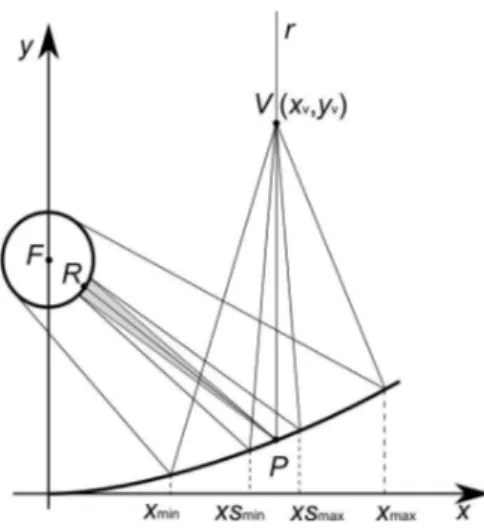
Following the VIM approach, the VISfield is based on the principle of ray reversibility, also known as the reciprocity theorem of Helmholtz [9]; that principle states that any ray of light in an optical system, if reversed in direction, will retrace the same path backwards. Let us consider the section of an ideal parabolic-trough concentrator shown in Fig. 3 and the ray r parallel to the parabola axes; r crosses the point V, hits the parabola in P, is reflected towards the focus F and finally hits the HCE in R, which is aligned with the points
P and F. Conversely, by reversing ray propagation, the ray emitted by R towards P, follows the same above
described path and crosses the point V. An observer in V see the parabolic mirror surface darkened by the HCE image spread between xmin and xmax, and in particular the image of R sighted with xv, the abscissa of V. All the rays emitted from any other point of the HCE and reflected in P do not reach V as well as all the rays emitted from R obliquely with RP. Supposing to increase the distance of V from the parabola to capture the far field image of the collector, it is clear that the ray r is very special because is the sole ray determining the far field image of P.
Fig. 3: reflected image of HCE observed from the view point V. An hypothetical spot of the solar radiation that would reflected by P will appear spread in the HCE image between xsmin and xsmax.
Anyway, for the actual purpose the important concept is that the point of the HCE which is reflected in P and sighted with xv corresponds to the spot-centre of the solar-radiation that would be reflected by P and intercepted by the HCE in perfect-tracking condition; the spot-radius would be s = FP tan(α), with FP optical-path length between P and HCE (as matter of fact, the HCE radius is much less than the focal length, then RP ≈ FP), and α the half-angle of the cone across which the solar radiation is spread. From V, the image of that hypothetical solar-spot on the mirror surface would be spread between xsmin and xsmax. As well xmin and
xmax, xsmin and xsmax can be determined by imposing the respect of the second law of reflection, i.e. the equality between incident and reflection angle; unfortunately there is no analytical solution and a numerical search is used. More precisely, as depicted in Fig. 4, given V and a point A on the HCE, let us consider the point B of the mirror and the angle αi and αr made by AB and BV with the normal of the ideal parabola, respectively; the B position is numerically adjusted to fulfils the condition αi = αr.
Fig.4: given V and a point A on the HCE, there is an unique point of the parabolic mirror where the ray coming from A is reflected towards V. In that point, incidence and reflection angles are equal, accordingly
with the second law of reflection.
Now let us suppose that for some reasons the slope in P deviates from that of the ideal-parabola for δradiant. From V the HCE image is shifted along the x axis of about 2Mδ FP, where M is the image magnification,
the reflected ray increases for 2δ , and consequently the impact point on the section of the HCE is shifted for 2δ FP; on the other hand, by the principle of ray reversibility, the image of the impact point remain sighted
with xv, then the HCE image has to shift of 2Mδ FP. A similar effect is caused also by deviation of the P ordinate, but at the typical values observed for good quality facet-mirror, about 1 mm, the amplitude is much less; therefore we neglect it.
The above considerations allow to get quantitative information about slope-deviation and local IF value (i.e. concerning the point P of the mirror) by the analysis of the position of the HCE image: said ∆ the image shift, the slope deviation is δ = ∆/ 2MFP, and with good approximation the local IF is given by the portion of the range (xsmin xsmax) appearing superimposed to the HCE image. As an example Fig. 5 show the frontal view of an experimental spare module 12 m long, oriented towards the horizon, from V in xv = 1.5 m and yv = 13 m about; in the picture are also drawn the lines corresponding to xmin, xmax, xsmin and xsmax. The lower half parabolic-trough is composed by ten facets of which only one is correctly aligned, as shown by the position of the HCE image with respect to the expected position. All the other facets should be adjusted for the reduction of the slope of 19 mrad about, being ∆ ≈ M 2 r and FP = 1810 mm. Considering the region
delimited by xsmin and xsmax, we can say that the local IF along xv is 1 trough the rightly aligned facet and 0 elsewhere.
Fig. 5: frontal view of an experimental spare module 12 m long, oriented towards the horizon, from V in xv = 1.5 m and yv = 13 m about; from the top to the bottom the lines correspond to xmin, xsmin , xsmax and xmax. In order to get the most complete information, this analysis has to be repeated on a set of frames captured from different observation points, with xv spanning the x axis from the vertex to the external parabola border; the optimal step between one frame and the following is the digital resolution of the parabola surface, that is the side of the pixel-image. With this criterion the number of frames to be captured by a Mpx camera is some hundreds.
It is noteworthy that when xv =0, the HCE is sighted with the parabola vertex. In this position the line passing along the HCE and the vertex is the reference line that has to be considered for all the others frames taken off the parabola axis; this is a fundamental criterion useful for the practical case and essential to makes the camera-pointing uncritical for the measurement results.
Once the module is completely scanned, the slope-deviation data can be organized as a two-dimensional matrix. Each sub-matrix, corresponding to a single facet, can be fitted with the simple equation b + a (z – z0 ), whose x-integral is
δ y = b (x-x0 ) + a (x-x0 ) (z-z0 ). (1) Generally the mirror-facets are hang to the mechanical structure by several fixing-points: generally 4 or 6 for the facet shaped as quarter and half of parabola, respectively. It is convenient to set x0 to the abscissa of the fixing-points closest to vertex (being the highest, they are the most difficult to adjust); then the values of Eq. 1 at the other fixing-points represent (reversed in sign) the adjustment amount needed to optimize the facet alignment.
With respect to the TOP technique this method is much more accurate because it takes into account not just a single frame, but a set of frames which gives a complete information of the facet-mirror, included the average IF. Moreover the VISfield allows to check also the shape quality of each facet-mirror: the low shape-quality facet-mirrors are those for which is not possible to improve IF; they have to be replaced if not satisfying an assigned threshold value.
In conclusion, the VISfield allows to evaluate the IF, and verify (and optimize) the mutual alignment between HCE and facet-mirrors. Therefore, the preliminary verification (and eventually optimization) of the HCE alignment with respect of the torque tube is essential, otherwise the global IF may degrade in tracking condition.
3.2 The instrument
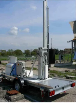
Considering the potential commercial application of the VISfield, since the beginning ENEA searched for a qualified industrial partner to produce the first prototype, and subsequently commercialize the future engineered version. MARPOSS [10], leading global supplier of precision metrology equipment, caught this opportunity and manufactured the hardware shown in Fig. 6; in the meanwhile ENEA developed the software, written in C++, using open source libraries as libdc1394, for the grab acquisition from a firewire camera, and opencv for the image management; the GUI was realized in Qt4. The image-processing is totally automated and it is based on the brightness contrast between the receiving tube of the HCE and sky.
Fig. 6: first prototype of the VISfield made by Marposs.
The prototype was conceived keeping in mind some important requirements: 1) inspection of a whole module 12 m long; 2) fast scan and image processing; 3) easy device to transfer. The first two statements have been accomplished by adopting the firewire-1394b camera Stingray F-504 B by AVT, equipped with a 8 mm objective: at full resolution (5 Megapixel), the frame rate is 9 fps; frontally, a 12 m long module is entirely viewed from 13 m about, which is compatible with the typical distance between two contiguous collector
rows in a solar field. To meet the third requirement, a 3.2 m long translational rail is installed on a cargo trailer able to travel on public roads; a special pivoting joint manually allows the operator to turn the rail horizontally or vertically, accordingly to the usage, transfer/parking or measurement.
The limit of 3.2 m length of the translational rail, about half of the typical parabola aperture width, was dictated by several reasons: i) keeping the cost of the system at a reasonable level (and then the selling price too); ii) having a device easy to carry; iii) maintain security of intervention (in the field, the adjustment of the fixing points of the mirror-facets composing the parabola above the vertex would be quite complicated and, above all, dangerous for the operators). It is in fact preferable to inspect and eventually adjust the lower half parabolic-trough, while the upper half will be analysed in a second stage with the module oriented in the opposite direction (rotated by 180 degree).
During the measurement, the cargo-trailer is stabilized by means of four hydraulically operated, retracted feet to guarantee the steadiness of the visual inspection of the module during the measurement cycle.
3.3. Results
The measuring cycle time, including the image processing performed with a notebook Toshiba Satellite A300-280 (Pentium T4200), is about 2 minutes long. Therefore the VISfield is fast enough to adjust the facets in real time, i.e. by executing a first scanning, adjusting the facets if necessary, and then checking the result with another optical scanning.
The most important output of the VISfield is the intercept-factor map; as an example the one achieved on a very old module of ENEA PCS is shown in Fig. 7; the ten facets composing the examined half-parabolic-trough are perfectly visible. In that map, dark, gray and white mean degraded-reflectance, IF < 1 and IF=1, respectively. In this case IF is evaluated in a theoretically perfect tracking condition, that is with the parabola-axis pointing the Sun. The software gives also the IF averages of the single facet-mirrors; Tab1 shown the individual IF also with Sun declination of 30 and 60 deg; in this condition the Sun lies on the plane identified by the vertex line and the parabola axis, but inclined with respect of the parabola axis. Please note that in the IF averaging the degraded-reflectance regions are not considered.
Facet-mirror
0 deg 30 deg 60 deg
1 1.000 0.998 0.979 2 1.000 1.000 0.992 3 0.999 0.998 0.977 4 0.998 0.997 0.971 5 1.000 0.999 0.974 6 1.000 1.000 0.993 7 0.998 0.998 0.984 8 0.999 0.998 0.977 9 0.995 0.992 0.965
10 0.999 0.998 0.978
altogether 0.999 0.998 0.979
Table 1. IF averaged on the facet-mirrors at the Sun declination angles 0, 30 and 60 deg.
Fig. 7: intercept-factor map of an old PCS module. Dark, gray and white mean degraded-reflectance, IF < 1 and IF=1, respectively.
Another important VISfield feature is the action to take for modifying the facet fixing-points and adjusting the facet-surface in accordance to the theoretical parabola shape. Fig. 8 resumes the indications for both central and outer fixing-points; in this specific case, the facet are mounted on the supporting-structure by 6 fixing-points: 2 inner, 2 central and 2 outer. The corrections are calculated assuming that the two inner fixing-points (the closest to the vertex) were properly set. Because central and outer corrections have the same sign, and the absolute value of the outer is always greater than the central one, a not optimal alignment of the wings departing from the torque tube is expected; that is confirmed by the simple tout-string technique shown in Fig. 9.
Fig. 9: tout-string running over the wings, near the outer fixing-points; the extreme wings of the module where the tout is hang, and perfectly adherent, are not reported.
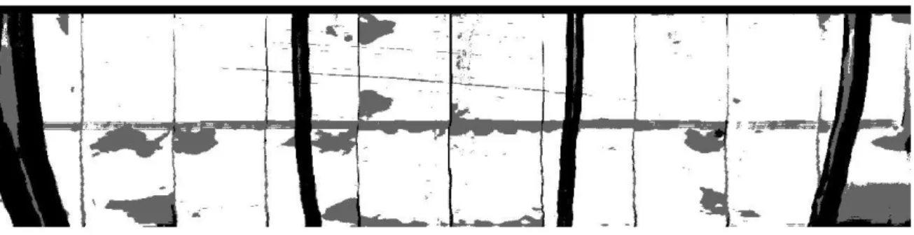
The third main feature of the VISfield is the check of facet-mirror compliance: once the fixing-points are modified accordingly with the VISfield suggestions, and the residual corrections are less than 1 mm, the compliance of each facet-mirror is related to its IF, local and mean; that gives an important tool to verify in situ the facet-mirror quality and allow to reject the ones not enough performing. As an example Fig. 10 shown the final map of a re-aligned module; disregarding the black strips because due to the thermal-insulation protection applied in the HCE-unit connections, several facet-mirrors show large regions where the shape is not sufficiently close the one of the ideal-parabola to allow the complete capture of the reflected radiation.
Fig. 10: final map of a re-aligned module; the black-grey strips are related to the thermal insulation protection applied in the HCE-unit connections, elsewhere the grey regions means that IF < 1.
References
[1] A clear overview of CSP technology is given at http://www.nrel.gov/csp/pdfs/39291.pdf
[2] T Wendelin, Proceeding of the DOE Solar Program Review Meeting, Golden, CO, October 25-28, Paper No. DOE/GO-102005-2067 (2004).
[3] E. Lupfert, K. Pottler, S. Ulmer, K.J. Riffelmann and B. Schiricke, Proceedings of ISES2005 International Solar Energy Conference, Orlando, FL, August 6-12 (2005).
[4] K. Pottler, E. Lupfert, G.H.G Johnston, M. R. Shortis, J. Sol. Energy Eng., 127 (2005) 94-101. [5] R. B. Diver, T. A. Moss, J. Sol. Energy Eng., 129 (2007) 153-159.
[6] Italian patent deposited on March 3rd, 2008, No RM2008A000151. [7] See http://www.enea.it/com/solar/lab/collettori.html
[8] See http://www.leica-geosystems.com/en/Laser-Stations-Leica-TDA5005_787.htm
[9] M. Born, E. Wolf, (2005). Principles of Optics, 7th ed., Chap. 8, pag. 423, Cambridge University Press, Cambridge.