Contents lists available atScienceDirect
International Journal of Fatigue
journal homepage:www.elsevier.com/locate/ijfatigueEffect of heat treatment on fatigue behavior of as-built notched Co-Cr-Mo
parts produced by Selective Laser Melting
Seyed Mohammad Javad Razavi
a,⁎, Andrea Avanzini
b, Giovanna Cornacchia
b, Luca Giorleo
b,
Filippo Berto
aaDepartment of Mechanical and Industrial Engineering, Norwegian University of Science and Technology (NTNU), Trondheim, Norway bDepartment of Mechanical and Industrial Engineering, University of Brescia, Italy
A R T I C L E I N F O Keywords: Co-Cr-Mo alloy Fatigue Heat treatments Notch SLM A B S T R A C T
In this paper Cobalt-Chromium-Molybdenum (Co-Cr-Mo) specimens produced by Selective Laser Melting (SLM) for biomedical field were studied. In particular, fatigue tests were carried out comparing as-built condition with Hot Isostatic Pressing (HIP) and a heat treatment under vacuum condition. The influence on microstructure and fatigue properties was investigated on plain specimens and with a V-notched geometry. Both vacuum heat treatment and HIP had effects on the microstructure and internal defects, which resulted in an enhancement of quasi-static and fatigue properties. Lastly, notch sensitivity and applicability of ASED failure criterion for fatigue life prediction notched specimens were evaluated.
1. Introduction
Cobalt-Chromium (Co-Cr) alloys were originally studied in 1907 by Haynes, who showed that by adding Molybdenum (Mo) or Tungsten (W) to the basic binary Co-Cr alloy a significant increase in strength could be achieved[1]. Over the years, thanks to their high versatility and durability, these alloys proved to be especially suitable for bio-medical applications [2]. In particular, the Cobalt-Chromium-Mo-lybdenum (Co-Cr-Mo) alloy provides one of the best balance between mechanical strength and wear, associated with remarkable corrosion resistance and biocompatibility [3]. Co-Cr alloys are generally char-acterized by high melting point, high hardness, and low machinability [4]. Traditional processing routes include investment casting, hot for-ging and subtractive processes (CAD/CAM milling). Investment casting (“lost wax” process) is possibly the most common, especially in den-tistry, because it allows manufacturing devices and components with intricate shapes that would not be feasible with forging techniques. However, the steps involved are time-consuming and many processing variables may affect the quality of cast parts. Forged constructions generally exhibit improved mechanical properties, but typical dis-advantages are higher cost and limitations on component complexity [4].
In light of this, Additive Manufacturing (AM) technologies could indeed provide an optimal trade-off between the need to increase manufacturing speed for highly customized and complex parts, while
achieving required mechanical properties with near-net-shaped com-ponents containing fewer defects and cracks. These potential benefits motivated several instigations on the possibility to produce AM parts with Co-Cr-Mo alloys. In the orthopedic field, manufacturing of a dense femoral component was reported in [5], whereas investigations on cellular structures were reported in [6,7] showing that by grading material porosity it is possible to achieve stiffness compatible with bone structures. Potential applications in dentistry include components of removable partial denture (RPD), as clasp retainer[8], whereas in the cardiovascular field, where these alloys are used for stent production [9], the possibility to use SLM Co-Cr-Mo has also been recently explored [10].
As apparent, components for such critical applications usually serve under cyclic loadings in the living body environment. Their reliability is largely determined by resistance to fatigue fracture, which has been identified as a major problem that may lead to loosening and ultimate failure[11]. In turn, fatigue failure of mechanical components depends on the combination of several factors, including intrinsic fatigue be-havior of the material in relation to processing route, surface finishing and local stress distributions due to design requirements.
From a material perspective, quite obviously, the microstructure resulting from processing technology and/or additional heat treatments has a great influence on fatigue life. Due to their relevance as bioma-terials, fatigue strength of Co-Cr alloys produced with traditional methods, such as forging or casting has long been investigated (see
https://doi.org/10.1016/j.ijfatigue.2020.105926
Received 16 July 2020; Received in revised form 31 August 2020; Accepted 1 September 2020 ⁎Corresponding author.
E-mail address:[email protected](S.M.J. Razavi).
Available online 06 September 2020
0142-1123/ © 2020 The Author(s). Published by Elsevier Ltd. This is an open access article under the CC BY license (http://creativecommons.org/licenses/BY/4.0/).
reviews in [12,13]), yet it is difficult to assume any equivalence in terms of fatigue properties between different processing routes. As re-marked in [14,15], in AM products the observed microstructure, in particular phases, grain size and defect types, can be remarkably dif-ferent. In this context, it is useful to highlight that the most widely used cast Co-Cr-Mo alloys in biomedical field contain 28%Cr, 6%Mo and up to 0.35% of C. The percentage of carbon is defined by the employed production technology (i.e. maximum limit to optimize the fluidity while the lowest limit for ductility). As the percentage of carbon in-creases, the volume fraction of carbides increases and the alloy has the highest hardness, strength and wear resistance but at the same time, reduce the ductility of the alloy. The metal matrix consists of a variable mixture of γ phase FCC (stable at high temperature) and ε phase HCP (stable at low temperature). In as-built SLM Co-Cr-Mo alloy a fine cel-lular structure is observed, and the carbides seem concentrated mainly on the grain boundaries formed by the solidification. Also in this case the carbon in solid solution influences the relationship between the metal matrix phases, but γ phase seems to be dominant in different research works[3,16]. SLM-produced Co-Cr-Mo alloys were reported to display superior homogeneity compared to cast Co-Cr-Mo alloys, which are inherently associated with large initial grain size, non-homo-geneities, and other casting defects.
When prepared by SLM, strong temperature gradients during melting and subsequent rapid cooling of the alloy results in the creation of a fine cellular microstructure, characterized, according to[17], by grain boundaries depleted in Co and enriched in Mo and minimization of carbide precipitation and formation of a martensitic ε phase at the surface.
For AM Co-Cr alloys, although investigations on the correlation between microstructure and mechanical, tribological and corrosion properties can be found in the literature[8,14,17,18], at present very few studies has considered fatigue loading condition. In particular, in [19]the effects of HIP on mechanical properties and fatigue of SLM Co-Cr-Mo were investigated, in comparison with as-cast. Fatigue testing on machined samples, under tension/compression constant amplitude loading, showed low fatigue strength in as-built condition, whereas a post densification and heat treatment step by HIP led to extraordinary high values of fatigue strength (σfA= 450–480 MPa). Fatigue perfor-mance of Co-Cr-Mo alloy produced by Electron Beam Melting (EBM) was reported in[20], for machined specimens that were subjected to HIP and heat treatment prior to testing. Additionally, in[11]the pos-sibility to improve the fatigue strength of EBM Co-Cr-Mo specimens for clasp retainer in removable partial dentures with heat treatments was reported.
Overall, these studies indicate that stress relieving heat treatment and HIP may play a relevant role on improving fatigue performances of AM Co-Cr-Mo, but the knowledge of fatigue behavior remains largely incomplete due to the complexity of microstructure and the number of factors involved. Moreover, some of the data refer to different manu-facturing methodologies (i.e. EBM, SLM, cellular structures) but prop-erties may significantly vary also depending on specific AM technology process parameters and post treatments.
On the other hand, any real component necessarily includes geo-metrical features dictated by structural or functional design require-ments, that may locally act as discontinuities, resulting in stress gra-dients in localized areas that commonly affect fatigue performances negatively. Limited research studies have evaluated the fatigue beha-vior of AM parts in the presence of geometrical discontinuities con-sidering the effect of surface roughness and internal defects [21–26]. Unfortunately, very limited design criteria were presented for AM components considering stress concentration phenomena[26–28]. This is particularly true for SLM Co-Cr-Mo alloys for which, to the best of authors' knowledge, there are currently no investigations concerning the fatigue behavior in the presence of a notch. Basing on the above-mentioned observations, the present work aims to investigate how microstructural changes induced by heat treatments may affect fatigue
life in the presence of notches acting as a stress raiser. In order to in-vestigate the influence of HIP and selected heat treatment under va-cuum condition in comparison with as-built, fatigue tests were carried out on Co-Cr-Mo specimens produced by SLM for both smooth and V-notch condition, with as-built surface.
In the first part of the paper, details of the manufacturing method and heat treatments that were used for the fabrication of the specimens are described and the theoretical background of Average Strain Energy Density (ASED) criterion is provided. Afterward, the microstructures and fatigue test results of smooth and notched Co-Cr-Mo specimens are presented and compared. Lastly, applicability of ASED failure criterion for fatigue life prediction notched specimens is evaluated.
2. Materials and methods
2.1. Powder, processing parameters and specimen geometry
A commercial Co-Cr-Mo powder produced by LaserForm® was used. Its nominal composition is reported inTable 1.
The size and shape of powder particles were preliminarily in-vestigated on three samples which were analyzed using scanning elec-tron microscope (SEM) (LEO EVO-40 XVP), acquiring ten different images at the 5000× magnification for each sample. As shown inFig. 1, the powder consisted of particles with spherical shape and different diameters (range 1.1–23.8 µm, average dimension 6.9 ± 1.95 µm). Assuming as a reference UNI EN ISO 643 and ASTM E112 for grain's dimension in steels, the particles could be further classified according to their average dimensions as large (12 ± 1.91 µm), medium (5.8 ± 1.45 µm) and small (2.8 ± 1.45 µm) size.
The specimens for mechanical characterization and fatigue were produced by means of SLM with a ProX® DMP 100 system.Fig. 2shows the geometries of dogbone specimens for tensile tests and smooth and V-notched specimens used for fatigue testing.
The specimens were built along the vertical direction (seeFig. 3a), with a layer thickness of 30 µm, and a hatching distance of 10 µm. For each printing session 20 specimens were printed (see example for smooth V-notched specimens in Fig. 3b). No surface treatment was applied to the fabricated specimens.
2.2. HIP and vacuum heat treatment
In SLM products post-fabrication heat treatments have a consider-able influence on the mechanical properties of Co-Cr-Mo alloys. In fact, in as-built condition, the microstructure usually consists of fine elon-gated grains with preferential orientation associated with the build
Table 1
Nominal chemical composition (wt. %) of the commercial LaserForm powder.
Cr Mo Si Mn Fe C Co CoCrMo 28–30 5.0–6.0 0.0–1.0 0.0–1.0 0.0–0.50 0.0–0.02 Balance
10 μm
M
L
S
Fig. 1. Powder particles classification based on size; small (S), medium (M),
direction, which may result in a directional dependency of tensile and fatigue properties. Post-treatments may help to remove accumulated thermal stresses and modify the microstructure in terms of phases, grain size, and porosity, potentially improving associated tensile or fatigue properties.
In the present study, two types of post-production treatments were considered, HIP and vacuum heat treatment, so as to provide evidence of the differences between pressurization and vacuum conditions.
HIP is a form of heat treatment combined with high pressure in which time at elevated temperature and pressure allows plastic de-formation, creep, and diffusion to occur. It was selected because it is often considered as the most effective post-manufacturing treatment available for remedying process-related defects of AM parts and im-proving their fatigue performance [19]. HIP is a special process that requires dedicated technologies and a high-pressure chamber, to deal with elevated temperature and the high involved pressures, usually applied by means of an inert gas (argon). In the present study, HIP process was carried out at the Bodycote plant of Coordonnées (Magny Cours France) and specimens were treated at 1200 °C under a pressure of 1020 bar for four hours in a shared cycle in argon environment that the company specifically adopt for this alloy.
Considering heat treatments, a survey of different heat treatments reported on technical datasheets from the manufacturers of Powder Bed Fusion (PBF) technologies and the literature showed that for this type of alloy different approaches are possible[14,17,29,30]. The main heat
treatments include stress relief at 800 °C for 20 min, solution heat treatment with a sequence of steps at a temperature between 650 °C and 1050 °C and heat treatment at 1150 °C for 6 h (Laserform, Renishaw, EOS).
Among these, the heat treatment at 1150 °C for 6 h was chosen, which should promote significant changes in the microstructure, with homogenization and recrystallization leading to isotropic properties of the metal matrix. Moreover, for comparison purposes, this heat treat-ment features a combination of temperature and times closer to HIP and according to[17]is an effective method for eliminating the residual stress, leading to a homogenized microstructure and satisfactory duc-tility.
Heat Treatment on Co-Cr-Mo samples was performed by the com-pany TAV Vacuum Furnaces (Caravaggio (BG), Italy) using a horizontal furnace for vacuum heat treatment. The specimens, before being in-serted into the thermal chamber, were placed over alumina plates and then covered with a metal ring in order to keep them isolated and en-sure uniformity of temperature. After reaching a high vacuum level in two minutes, the heat treatment at 1150 °C for 6 h was carried with the following steps:
•
Heating 1: Heating from room temperature to 950 °C (10 °C/min) with 1 mbar of partial pressure (Pp) of Ar;•
Maintaining 1: Maintaining at 950 °C for 90 min with 1 mbar of Ppof Ar;Fig. 2. Specimens geometries (a) dogbone, (b) smooth, and (c) V-notch with a thickness of 3 mm. (unit: mm).
(a)
(b)
2 mm 2 mm
•
Heating 2: Heating from 950 °C (10 °C/min) to 1150° with 1 mbar of Ppof Ar;•
Maintaining 2: Maintaining at 1150 °C for 360 min with 1 mbar of Pp of Ar;•
Cooling: Radial cooling from 1150 °C to room temperature with 3 bars of Ar.During the cooling phase from 1150 °C to 400 °C the cooling rate (265 °C/min) was monitored with a thermocouple. The specimens were subdivided into three groups referred to in the paper As-Built (AB), heat treated in vacuum (HT), and HIP depending on post treatment. 2.3. Metallography
For metallographic observations, the SLM specimens, AB, HT and HIP, were sectioned both orthogonally and parallel to their axis in order to evaluate the grade of anisotropy/isotropy in each condition. Successively, they were mechanically prepared following the conven-tional metallographic grinding and polishing procedures (ground with SiC papers and polished with 1 μm diamond paste). A preliminary ex-amination of the as-polished samples was carried out to study the porosity; subsequently the samples were etched using an electrolytic solution (5 ml HCl, 10 g FeCl3, 100 ml water, 6 V for few seconds), according to ASTM E-407 Standard (section for Cobalt base alloys), which allowed the microstructure observations. The microstructures were investigated on a macro scale using a LEICA DMI 5000 M optical microscope (OM) (Wetzlar, Germany) equipped with Leica Application Suite (LAS) image analyzer.
2.4. Mechanical characterization: tensile and hardness tests
The influence of post-treatment on the mechanical properties, in comparison with AB conditions, was investigated through hardness and tensile tests. Tensile tests were carried out on dogbone specimens as per Fig. 2a. For each specimen condition (i.e AB, HT, HIP), three dogbone specimens were subjected to tensile test on electromechanical testing machine Instron 3369 universal testing machine (50 kN) (Massachu-setts, USA) using extensometer for strain measurement (approx. strain rate 0.01 s–1) following UNI EN ISO 6892-1:2009.
The influence of microstructural changes induced by HT and HIP was also investigated by carrying out micro hardness measurements, along the transversal and longitudinal direction with respect to building axis Z. Vickers micro-hardness (HV) tests were carried out on the po-lished cross-sections of the specimens under 300 gf load applied for 15 s, by means of a Mitutoyo micro Vickers hardness tester (Kawasaki, Japan), according to ASTM E92-16. In particular, for the Vickers micro hardness test, ten measures on mid-length cross section of each sample were carried out.
2.5. Fatigue test
Fatigue tests were carried out on an average of ten specimens for each geometry (smooth and V-notched). Axial fatigue loading was ap-plied using an MTS Landmark servo-hydraulic test machine (Minnesota,
USA) equipped with a 50 kN load cell. All tests were carried out at room temperature, under load control using a sinusoidal signal in uniaxial tension, with a frequency of 30 Hz and a load ratio of R = 0. The run-out limit was set to 2 × 10⁶cycles. The fracture surface of failed spe-cimens were analyzed using scanning electron microscope (SEM) (FEI, Quanta™ 650 FEG, Oregon, USA) to evaluate the fatigue failure me-chanisms.
2.6. Theoretical fatigue assessment method 2.6.1. Strain energy density as a design parameter
Local failure approaches consist of a wide category of fatigue failure prediction methods in components with complex geometries. According to the fundamentals of these approaches, fatigue failure occurs when the key parameter (e.g. stress, strain, strain energy density (SED), etc.) reaches its critical value at a material-dependent critical distance from the notch root [31]. Among the available local fatigue approaches, average strain energy density (ASED) criterion has been widely used for failure prediction of various materials and geometries showing pro-mising predictions by use of relatively simple procedure[32–34]. Ac-cording to the ASED criterion, failure occurs when the average value of SED in a control volume around the notch is equal to a critical value. Under plane stress or plane strain states of stress, the control volume becomes an area as shown inFig. 4, where the size of control volume, R0is independent of the notch geometry[35,36]. InFig. 4, 2α is the notch opening angle, ρ is the notch root radius, R0is the radius of control volume, and r0is the distance between the notch root and the center of the circle defining the outer boundaries of the control volume in blunt notches.
Lazzarin et al.[35,37]extended the concept of ASED criterion for the synthesis of fatigue data obtained by experimentally testing dif-ferent geometries of welded joints. According to their findings, ASED can provide a master curve for fatigue data of a certain material, in-dependent of the geometry of the tested specimens. This master curve can later be used to predict the fatigue behavior of notch components of different geometries without the need to perform new experiments.
Under mode I fatigue loading, the radius of control volume, R0can be estimated as a function of the fatigue limit of smooth specimen, ΔσA and the notch stress intensity factor range at fatigue limit of notched specimens, KAV using the following equation[35,37]:
= R 2e KAV A 0 1 1 1 1 (1) in which e1is a function dependent on the notch opening angle 2α and λ1is the Williams’ series eigenvalue[38]. The use of fatigue limit of smooth specimen in this formula is to quantify the influence of surface roughness and internal defects in the specimen, in the absence of any global stress concentration effect. In the current study, the fatigue limit of tested specimens was obtained at 2 × 10⁶cycles.
The average SED range for smooth specimens is defined as =
W¯ 2E, in which Δσ is the applied stress range in the net section of the specimens and E is the elastic modulus of the material [35]. Dealing with blunt notches under mode I fatigue loading, the following expression can be employed to obtain the average strain energy density range[36]: = × × W F H R E ¯ (2 ) 2 , 0 tip2 (2) where the function F is dependent on notch opening angle 2α, the function H is a dependent on notch opening angle 2α and the ratio of control volume radius to notch root radius (i.e. R0/ρ) and tip is the tensile stress range at the notch tip. Alternatively, the average SED range can be directly obtained using linear elastic finite element (FE) analysis.
Fig. 4. Control volume (area) for (a) crack, (b) sharp notch, and (c) blunt
2.6.2. Numerical analysis
Two-dimensional linear elastic analyses were performed to obtain the stress concentration factor, Kt, and SED values. For this aim, elastic moduli and Poisson’s ratios of the tested materials were used as input in the numerical analyses. In order to assure the accuracy of the FE results, mesh convergence analyses were performed resulting in a minimum element size of 2 µm for stress analyses and a larger element size of 200 µm for SED analyses. Due to independency of SED values to the mesh size, larger element size could be used for that aim[33]. Unit stress was applied to the net section of double symmetric FE models and the peak stress at the notch tip, representing the stress concentration factor was obtained for both smooth and notched models. The fatigue notch factor, Kfwas then obtained using the experimental values by dividing the fatigue limit smooth and notched specimens at 50% probability of survival considering 2 × 10⁶cycles as the limit number of cycles (i.e. Kf= Δσ50%|smooth / Δσ50%|notched). The notch sensi-tivity of material in various post-treatment conditions was calculated using the expression q = (Kf– 1)/(Kt– 1). According to the definition of notch sensitivity, q = 1 (i.e. Kf= Kt) represents a material which is fully sensitive to the presence of geometrical discontinuities, while
q = 0 (i.e. Kf= 1) represents equal fatigue strength of smooth and
notched specimens revealing a material insensitive to the presence of geometrical discontinuities.
3. Results
3.1. Mechanical properties
InTable 2key mechanical properties from the tensile test are re-ported together with average values of hardness. Representative stress–strain curves of the tested material are provided as supplemen-tary data. Overall the range of values of yield stress Rp02and ultimate tensile strength Rmis similar to literature data reported in[39]and, as a reference, in all cases these properties compare favorably with minimum requirements stated in class 5 of ISO 22674 standard[40] concerning metallic materials for parts requiring high stiffness and strength, as fixed and removable restorations and appliances in den-tistry.
Yield stress Rp02is slightly decreased by post-treatments whereas ultimate tensile strength Rmis slightly increased. A remarkable increase of Young's modulus E and Elongation at failure Atcan be instead ap-preciated. In particular, the change induced by HIP and examined HT is more apparent considering the increase of ductility related to the dra-matic change of elongation at failure (At), from approx 6% to 25–30%, as a consequence of re-crystallization processes. The HV hardness va-lues of AB samples are slightly lower compared to literature[41]. A porosity analysis was also carried out on micrographs using the method showing a decrease of porous area from an average value of 1.25% ( ± 1.08%) in AB condition to 0.92% ( ± 0.66%) after vacuum HT and 0.54% ( ± 0.27%) after HIP.
3.2. Metallurgical characterization
Micrographs taken along different planes are reported inFig. 5, in which a comparison of the three examined conditions helps to under-stand the significant differences originating from post-treatments. OM
investigations on AB samples highlight the stacking scheme of the process. Micrographs taken on the longitudinal section (i.e. parallel to building directions) show typical arch-shaped boundaries on average normal to the building direction. The transversal section revealed a columnar appearance of structure along the hatching line.
Previous investigations reported in the literature indicate that SLM Co-Cr-Mo alloys in AB condition exhibit a fine cellular microstructure containing carbide precipitation, as a consequence of strong tempera-ture gradients during melting and subsequent rapid cooling of the alloy occurring during SLM. As mentioned earlier, Co–Cr–Mo alloys are also well-known to contain two main phases, HCP (ε) and FCC (γ). According to the phase diagram, the HCP phase is more stable at room temperature, but as summarized in[17], FCC-to-HCP transformation rarely occurs under normal cooling conditions. This transformation can be induced thermally (by quenching from temperatures corresponding to the FCC region of stability), isothermally (by aging at temperatures between 650 °C and 950 °C) or through plastic strain.
Due to the rapid solidification associated with SLM process, this process, inhibits martensite formation and according to[14,42], the γ-phase is predominant in AB condition, since the alloys remain in the martensite field for short time. In particular, for an as-built SLM Co-Cr-Mo alloy in[29]XRD spectra revealed the presence of a mixture of γ-phase and ε-γ-phase and quantitative analysis indicated a percentage of ε phase of about 30%.
According to the macroscopic analysis of HT samples (Fig. 5), a completely modified microstructure could be immediately seen, com-pared to AB samples. First of all, the stacking scheme of single weld beads was no more visible. The carbides are highly dissolved resulting in very small precipitates within the grains and on the grain boundaries. Longitudinal and transversal views show the presence of equiaxed grains without apparent differences of orientation and size, a sign of complete recrystallization occurred. The most important consequence that can be expected from this microstructural modification is the iso-tropy, which may be an advantage in all steps of the manufacturing process and in service.
The heat treatment can change the ratio of the γ-phases and ε-phases in Co-Cr-Mo alloys manufactured by SLM and the volume frac-tion between γ and ε phases varies upon the heat-treatment tempera-ture[16]. In particular, in[17], it is reported that the volume fraction of the ε-phase decreases with the increasing heat treatment tempera-ture.
For the present work, the micrographs show the presence of large number of annealing twin boundaries, characteristic of a low stacking fault energy material suggesting that recrystallization occurred. As re-ported in [17]for Co-Cr-Mo heat treated at 1150 °C, the γ-phase is prevalent, where at the same temperature used in the present work the ε-phase approached very low values (lower than 5%). Since ductility increases with the increasing volume fraction of the γ phase[17], this interpretation could explain the significant increase of elongation at break observed in tensile test after HT.
Dealing with residual stress, Bawane et al.[43]reported a range of 550–950 MPa residual stresses in laser powder bed fused (LPBF) Co-Cr-Mo specimens. Lower levels of residual stresses equal to 265 MPa were later reported by Chimmat and Srinivasan[44]using different process parameters. In both cases, performing heat treatment at 1150 °C re-sulted in drastic reduction of residual stress to a negligible level
Table 2
Mechanical properties.
At(%) Rp02[MPa] Rm[MPa] E [GPa] HV
AB 5.88 ± 0.21 590.92 ± 13.54 898.40 ± 2.26 166.8 ± 2.4 393.9 ± 14.9
HT 26.26 ± 3.78 536.75 ± 7.47 972.42 ± 0.71 226.9 ± 5.1 309.4 ± 20.4
HIP 25.23 ± 0.15 514.35 ± 28.91 936.12 ± 8.05 202.7 ± 3.7 321.8 ± 10.2
approved by X-ray residual stress analysis. The presence of residual stresses in AB components were reported to be the driving force for transformation of columnar dendritic microstructure of AB material to equiaxed grains after heat treatment. It is worth mentioning that heat treatment up to 1050 °C does not eliminate the residual stresses in LPBF Co-Cr-Mo specimens[17,44].
Even in the case of HIP process both in the longitudinal and in the transversal view it is possible to observe the presence of the equiaxed grains, which reveals the disapperance of anisotropy. According to [19], after the HIP process, the microstructure is completely re-crystallized with a regular grain structure. In particular, the micro-structure of the HIP is homogenous with a presence of γ-phase, as confirmed by[19]: a possible reason for this fact may be due to slow cooling rate typical of the HIP process, which favored their formation. After these observations emerge as the mechanical properties data obtained are strictly linked to the microstructural modification, as also remarked in[45]in which work additively manufactured Co-Cr alloys were found to exhibit microstructural inhomogeneity and a dependency of mechanical properties on the evolution of microstructure as a con-sequence of heat treatments. In particular, for the present work, it is possible to observe that AB sample consist in a fine cellular structure, and small precipitates seem concentrated especially on the grain boundary between the grains formed by solidification of the liquid front. Considering that the carbon content can form different types of
carbides in matrix and the size, phase and content of carbides influence the microstructure and mechanical properties of cobalt alloys[16], in this case, for AB samples, γ phase was dominant. The observed AB microstructure leads to a reduction in dislocation mobility, conse-quently high hardness and high mechanical strength are obtained. Vacuum heat treatment and HIP eliminated the inhomogeneity and uniformed the microstructure. The HT and HIP specimens consist al-most entirely of the γ phase according to literature where it has been demonstrated that the volume fraction of the ε phase decreases with the increasing heat treatment temperature, reaching extremely low values for temperatures above 1150 °C [17]. Therefore, the observed mod-ification of mechanical properties could be attributed mainly to the differences in the grain size and the precipitate distribution resulting from different time, temperatures and pressure conditions of post treatments. In particular, HT was conducted at 1150 °C for 6 h under high vacuum (10−6mbar) followed by cooling step in argon with a cooling rate of about 5 °C s−1. HIP process was realized at 1200 °C under a pressure of 1020 bar for 4 h in a shared cycle in argon en-vironment. The cooling step was in the furnace with argon protection and an estimated cooling rate of about 0.09 °C s−1. The HT faster cooling generated a finer microstructure, more advisable for structural purposes, whereas for the HIP grain growth occurred and larger grain could be observed also in comparison with AB specimens. For the HT and HIP specimens recrystallization occurred due to the fast
Z Y X HIP HT AB YZ XY
solidification during SLM that is the driving force for this phenomenon; in fact, the sequence rapid heating/cooling of the powder during SLM causes thermal stress that induces the recrystallization at high tem-perature in the HT and HIP processes. Because of recrystallization, all precipitates dissolved into the matrix, increasing the elongation of the specimens and decreasing their hardness and tensile yield strength [46]. The high temperatures of HT and HIP treatments also encouraged the formation of annealing twin boundaries in CoCr alloys during re-crystallization from the stacking fault bands[47–49]. Previous studies have shown that twin boundaries in FCC alloys increase the resistance to carbide precipitation [50] intergranular stress corrosion cracking [51]and have reduced susceptibility to hydrogen embrittlement[52]; however, grain and twin boundaries represent specific sites for cyclic slip localization and fatigue crack nucleation sites in FCC materials [53–55]. For the materials examined in the present work, in the HT specimens many annealing twin boundaries were detected into equiaxed grains, on the other hand, for HIP a decrease of annealing twins is observed with respect to HT ones. The presence of a large fraction of annealing twins contributed to the increase of ductility of the material, more marked for HT.
3.3. Fatigue test results
Results obtained from fatigue test data and statistical elaborations for smooth and samples are reported inFigs. 6 and 7for AB, HT and HIP conditions. Values of stress amplitude related to survival probabilities of 10, 50, and 90%, the inverse slope of the Wöhler curve, k and the scatter index Tσ(the ratio between the stress amplitudes corresponding to 10% and 90% of survival probability) are reported in the above-cited figures. Specimens survived over 2 million cycles are considered as run out and marked up with an arrow. The fatigue strength of smooth specimens with AB, HT, and HIP conditions at 2 × 10⁶cycles were 135, 380, and 318 MPa. While in the case of notched specimens, fatigue strengths of 89, 225, and 209 MPa were obtained. The material in AB condition exhibited a remarkably lower fatigue strength compared to both HT and HIP conditions, and also the reported values in the lit-erature for CoCr alloys manufactured with casting or forging processes. Both post treatments examined in this study significantly improved the fatigue performance, up to a range of maximum applied stress between ~300 and 400 MPa, which is comparable with fatigue strength reported for cast CoCr alloys[13]. The HT specimens show 181% and 153% higher fatigue strength compared to the AB parts revealing the sig-nificant influence of residual stress and microstructural features on fatigue behavior. Dealing with HIP specimens, although the fatigue strength of smooth and notched specimens was improved by 136% and 135% compared to the AB condition, however, the enhancement level is lower than the case with heat treatment at 1150 °C. Quite interestingly, the improvements of fatigue achieved with pressureless vacuum HT were higher than the ones subjected to HIP, despite the presence of some internal defects at the microstructural level in this case.
For notched samples, the general observed trend when comparing AB, HT and HIP cases were similar to the smooth specimens. As ex-pected, a reduction of fatigue strength could be noticed in comparison with smooth specimens. According to the fatigue data presented in Figs. 6 and 7, the notched specimens generally show lower the scatter index, Tσcompared to the smooth counterparts. Exception for this is the HT parts, which show similar scatter index for smooth and notched specimens. The highest scatter was observed for the smooth AB speci-mens. In this case, where the highest number of internal defects are present, the interaction between the surface defects and internal por-osity can intensify the stress at the root of surface defect, facilitating the initiation of the fatigue crack from these areas. Depending on the size and distance of internal porosities from the surface defects, the fatigue crack initiation life can vary. This dependency of the fatigue crack in-itiation life to the presence of internal porosities is thought to be the main reason for the highest scatter of the fatigue data for the AB smooth
specimens.
Both post treatments resulted in a higher inverse slope of the S-N curve compared to the AB condition. For higher stress levels HIP spe-cimens were slightly more resistant than HT counterparts whereas at lower stress levels the situation was reversed. As expected, lower in-verse slopes were obtained for the notched specimens compared to the smooth specimens. The HT and HIP specimens show a higher difference between the inverse slopes of the two geometries. For the sake of completeness, the detailed fatigue results are also summarized in Table 3. By comparing the reduction of fatigue strength in the AB notched specimens to smooth ones, one determines a fatigue notch factor Kfequal to 134.68/89 = 1.51 referred to 2 × 10⁶cycles, which is lower than the theoretical stress concentration factor Kt= 2.28 ob-tained from FE analyses. This reveals a notch sensitivity of 0.4 for the AB specimens. It is worth mentioning that the notch sensitivity for AB specimens not only is representative of the surface condition, internal porosity and microstructure of the material, but also the residual stresses within the specimens. Among the studied cases, HT specimens show the highest notch sensitivity of 0.54.
3.4. Theoretical fatigue assessment results
Finite element analyses were performed on different specimens geometries using the material properties of AB, HT, and HIP specimens. Critical radii of R0= 0.5, 0.39, and 0.49 mm were calculated respec-tively for AB, HT, and HIP specimens using the formulation given in Section 2.6.1.Fig. 8illustrates the results of ASED analyses with con-fidence bands of 10, 50, and 90%. All the analyzed fatigue data are presented in scatter bands of TW= 2.08, 2.13, and 1.48 for the speci-mens in AB, HT, and HIP condition, respectively. The mentioned SED scatter bands become equal to Tσ= 1.44, 1.46, and 1.22 when con-verted to an equivalent local stress range ( =T TW), which is sa-tisfactory considering the scatter index of every single series, sum-marizing the data from a single geometry and post treatment condition, expressed in terms of maximum applied stress. The reported SED scatter index values are well within the common values reported for welded joints and notched specimens made of various metallic materials [32,33].
3.5. Fractography
The fracture surfaces of the smooth and V-notched samples were analyzed using SEM. For comparison purposes, the specimens tested at σmaxof 400 MPa were selected. This stress level was common for all configurations (i.e. AB, HT, and HIP), and therefore, under the same applied stress, the influence of post-treatments could be better appre-ciated.Fig. 9 illustrates the representative fracture surface of fatigue tested specimens. Two distinct regions of fatigue crack growth and sudden failure are indicated on all tested specimens. The fatigue crack initiation in smooth specimens regardless of their post treatment always occurred only from one side of the cross section propagating toward the other side followed by sudden static failure. In the case of notched specimens, fatigue crack mostly initiated from both notches, propa-gating toward the center of the net section, revealing a central overload region in these specimens. Despite the equal applied stress to the spe-cimens shown inFig. 9, morphology of the fracture surfaces seems to be different. The fatigue failure portion of the total fracture area tends to be larger in post treated specimens (i.e. HT and HIP). This reveals higher stability of fatigue crack growth in these parts resulting in a higher number of cycles to failure under the same applied load.
Fig. 10shows the SEM fractography for the AB smooth specimens and the specimens subjected to different post treatments. According to the overall morphology of the fracture surfaces, the AB specimens show the highest roughness of failure features. This roughness was less sig-nificant for HT specimens and finally, a regular fatigue failure surface followed by sudden failure could be observed in HIP specimens. This
high tortuosity is thought to be directly related to the presence of large internal defects in AB specimens. The overall number of internal defects (mainly lack of fusion (LOF)) tends to decrease in the specimens
subjected to heat treatment. The higher ductility of the HT specimens together with a lower number and smaller size of internal defects re-sulted in a smoother texture of fracture surface compared to the AB 10
100 1000
1E+4 1E+5 1E+6 1E+7
Max stress, σmax [M Pa ] Cycles to failure, Nf AB, Smooth k = 3.21, Tσ= 1.64 PS= 10% PS= 50% PS= 90% 134.68 k 1 10 100 1000
1E+4 1E+5 1E+6 1E+7
Max stress, σmax [M Pa ] Cycles to failure, Nf AB, Notched k = 2.97, Tσ= 1.24 89.00 10 100 1000
1E+4 1E+5 1E+6 1E+7
M ax s tre ss , σm ax [M Pa ] Cycles to failure, Nf HT, Smooth k = 8.79, Tσ= 1.24 379.79 10 100 1000
1E+4 1E+5 1E+6 1E+7
M ax s tre ss , σm ax [M Pa ] Cycles to failure, Nf HT, Notched k = 4.82, Tσ= 1.25 224.65 10 100 1000
1E+4 1E+5 1E+6 1E+7
Max stress, σmax [M Pa ] Cycles to failure, Nf HIP, Smooth k = 5.44, Tσ= 1.23 318.58 10 100 1000
1E+4 1E+5 1E+6 1E+7
Max stress, σmax [M Pa ] Cycles to failure, Nf HIP, Notched k = 4.22, Tσ= 1.20 208.74
Fig. 6. Results of fatigue test for smooth and notched Co-Cr-Mo specimen tested under loading ratio of R = 0 and 30 Hz loading frequency.
10 100 1000
1E+4 1E+5 1E+6 1E+7
Max stress, σmax [M Pa ] Cycles to failure, Nf AB, Smooth HT, Smooth HIP, Smooth 10 100 1000
1E+4 1E+5 1E+6 1E+7
Max stress, σmax [M Pa ] Cycles to failure, Nf AB, Notched HT, Notched HIP, Notched
parts. Following this trend, the HIP specimens with the lowest number of LOF defects revealed the lowest tortuosity. For the HIP and HT conditions, it is possible to observe a transition from brittle to ductile behavior in the fatigue crack propagation and sudden failure regions testified by the presence of dimples and reduction of area due to necking in the specimens.
The detailed locations of fatigue crack initiation from the edge of the net section for different cases are shown. The initiation zone, similar in all conditions, is constituted by a faceted morphology. Due to pre-sence of fine solidification patterns in AB specimens, finer texture of failure facets could be observed in these specimens compared to the post treated specimens. The fracture in this area is “quasi-cleavage”, i.e. it does not occur in a single well-defined crystalline plane and the surface is made up of less smooth facets than in the case of a purely brittle fracture. This type of fracture occurs mainly in polyphasic alloys. The fatigue crack initiation in the specimens was governed by the presence of surface defects such as open LOF defects on the specimens. Fig. 11shows the SEM fratographies for notched specimens for all the post treatment conditions. It is noted that fatigue cracks nucleate on the surface also in V-notched specimens due to the roughness and SLM defects that operate as crack initiation points. Similar morphologies of fatigue features in the initiation and propagation zones were observed
for the notch specimens with two zones of symmetrical nucleation. The overall failure features in AB notched specimens have still brittle be-havior as compared to the post treated counterparts, as already seen in the case of smooth sample. The internal defects in AB specimens seem to follow the hatching pattern during fabrication, revealing the im-proper integrity of the sintered layers. This pattern is shown inFig. 11 using white dashed lines. The number and size of these internal defects seem to be reduced by heat treating the test specimens. In the case of HIP specimens, similar to smooth specimens, traces of internal porosity were significantly diminished.
Unlike the smooth specimens that the fatigue failure mainly started in a planar way, the notched specimens revealed multiple planes of crack initiation and growth which eventually merged after certain propagation through the net section. The crack initiation in AM com-ponents with as-built surface condition is thought to be controlled by the size of deepest surface defects. Dealing with components of complex geometries, both the geometry of part (i.e. global discontinuities) and the surface morphology (i.e. local discontinuities) play role in defining the location of fatigue crack initiation[56]. In the small region ahead of notch root, fatigue crack starts from the deepest surface defect. The interaction between the intensified stress due to the global notch and the local intensified stress ahead of surface defects can result in multiple critical locations on the surface for the crack to initiate. On the other hand, due to the larger stress gradient in the notched specimens, early fatigue crack initiation and longer fatigue crack propagation (due to lower driving force) is expected in these parts[57]. Due to lower crack initiation lives for the notched specimens, multiple cracks from dif-ferent planes can start at the same time in these specimens resulting in multi-planar fatigue propagation.
4. Discussion
Quasi-static and fatigue behavior of SLM Co-Cr-Mo specimens in the
Table 3
Fatigue behavior of the tested Co-Cr-Mo specimens.
Condition Geometry Δσ50%*[MPa] Tσ k Kt Kf q
AB Smooth 134.68 1.64 3.21 1.07 – – Notched 89.00 1.24 2.97 2.28 1.51 0.40 HT Smooth 379.79 1.24 8.79 1.07 – – Notched 224.65 1.25 4.82 2.28 1.69 0.54 HIP Smooth 318.58 1.23 5.44 1.07 – – Notched 208.74 1.20 4.22 2.28 1.52 0.41
* Fatigue strength at 2 × 10⁶cycles.
0.01 0.1 1 10
1E+4 1E+5 1E+6 1E+7
Av er ag e st ra in ene rg y den si ty , W [N mm /m m 3] Cycles to failure, Nf AB, Smooth AB, Notched 1 k R0= 0.50 mm k = 1.56, TW= 2.08, Tσ= 1.44 W50%= 0.05 Nmm/mm3(N = 2 × 10⁶) 0.01 0.1 1 10
1E+4 1E+5 1E+6 1E+7
Av er ag e st ra in ene rg y den si ty , W [N mm /m m 3] Cycles to failure, Nf HT, Smooth HT, Notched R0= 0.39 mm k = 2.89, TW= 2.13, Tσ= 1.46 W50%= 0.33 Nmm/mm3(N = 2 × 10⁶) 0.01 0.1 1 10
1E+4 1E+5 1E+6 1E+7
Av er ag e st ra in ene rg y den si ty , W [N mm /m m 3] Cycles to failure, Nf HIP, Smooth HIP, Notched R0= 0.49 mm k = 2.36, TW= 1.48, Tσ= 1.22 W50%= 0.22 Nmm/mm3(N = 2 × 10⁶)
presence of V-Notch has been evaluated in this study, comparing AB with HIP and HT conditions. The difference in mechanical properties of the studied SLM specimens was correlated to their microstructures and failure mechanisms. A theoretical synthesis of the fatigue data was performed using an energy-based fatigue model.
The results showed a very low fatigue strength of the material in AB condition, which is significantly improved by HIP and HT. Considering AB condition a first comparison can be made with results reported in [19], in which case fatigue testing was carried out on machined samples under tension/compression constant amplitude loading (stress ratio of R = −1). Also in this case fatigue strength in the SLM state (σfA= 128 MPa at 10 × 106cycles) was remarkably lower compared to the as-cast condition (σfA= 296 MPa at 10 × 106cycles)[19]. This was interpreted as the result of residual thermal stresses in the material induced by the laser process and of the remaining porosity, whose unfavorable shape served as fracture origin. Similar reasoning could apply for the present study, with the additional unfavorable effect of higher surface roughness associated with using as-fabricated geome-tries. This may explain the even lower values observed in this study, in combination with comparatively higher porosity, although it is worth mentioning that porosity measurement techniques were different, and with different load ratio (R = −1 instead of R = 0 in this research).
In the present study, HIP led to a significant increase in fatigue properties. Again, this is in line with findings reported in[19], where a post densification and heat treatment step by HIP led to extraordinary high values of fatigue strength (σfA= 450–480 MPa). Overall the re-sults observed in the present work seem to confirm the positive effect of HIP, although, differently to what reported in[19], they were not so close to the range reported for forged or cast-HIPped CoCr. HIP can increase the quality of additive manufactured components mainly through the reduction of internal defect sizes or microstructural changes. In fact, for SLM Co-Cr-Mo, the remarkable improvement of fatigue strength reported in[19]on machined samples after HIP, was interpreted by the authors as a consequence of the closure of all re-maining pores and complete recrystallization of the microstructure. However, the fatigue strength for additive manufactured samples can be reduced also due to several reasons, including rough as-built surface. Surface irregular features act as stress concentrations thus raising the
local stress and causing a fatigue crack initiation[22–24]. Accordingly, it has been observed that beneficial effect of HIPping on internal defect size and microstructural inhomogeneities may affect the fatigue per-formance especially for milled specimens[58], because in this condi-tion internal porosity, serving as a crack initiacondi-tion site, could play a more relevant role compared to surface defects where fatigue failure usually initiates. Recent studies on AM titanium alloys in[22]indicates that HIP has no enhancing effect on fatigue strength for EBM and SLM materials with rough as-built surfaces since the fatigue behavior will be dominated by the roughness rather than by internal defects. This may explain, the differences between the findings of the present work and [19]. It should be noted that due to complexity of AM parts produced for biomedical applications and also the need of the rough surface for better bone growth in the implants, machining would not always be an option for surface post treatment. In this scenario, the ultimate goal is to improve the fatigue properties of the AM parts with as-built surface. It should be mentioned that a combination of studied post treatments with recently proposed surface treatments such as chemical etching [59]requires further analyses.
On the other hand, HIP requires special procedures and dedicated plants. Therefore, any possibility of improving fatigue strength with heat treatment only, is particularly attractive when AM is concerned. Interestingly, in [19] it was observed that a pressureless post heat treatment, while not eliminating the remaining porosity of the SLM material, should reduce the thermal stresses, lead to a more favorable geometry of the cavities and also should influence the grain structure. In the same work, it was surmised that this might suffice to increase the fatigue strength of the SLM material to the level of as-casted Co-Cr-Mo. The influence of different types of heat treatment on mechanical properties of AM Co-Cr alloys has been examined in some recent studies [17,18,39]. Instead, investigations on fatigue are limited to data re-ported in[11]for EBM Co-Cr-Mo, in which two heat treatments were investigated (solution with/without aging). Aging at low temperature resulted in the transformation of initial as-built EBM γ + ε dual phase to the ε-HCP phase; after subsequent treatments, the ε-HCP phases re-verse transformed to the γ-FCC phase with refined grains. This latter condition allowed the most remarkable improvement in fatigue beha-vior, and showed that it is possible to improve fatigue performances by
d
e
h
c
t
o
N
h
t
o
o
m
S
As
-buil
t
H
ea
t tr
ea
te
d
HIP
1 mm 1 mm 1 mm 1 mm 1 mm 1 mmFig. 9. SEM fractograph of the tested smooth
and notched SLM specimens with different post treatments under maximum applied stress of 400 MPa. White arrows indicate the direction of fatigue crack growth from initiation location toward the interior region of the net section. The dashed white lines indicate the boundary be-tween the fatigue failure and sudden failure. Note the reduction in area due to plastic de-formation in the final stage of failure for HT and HIP specimens.
heat treatment only.
While results reported in [11]seem to support the possibility to improve fatigue performances, a more complete investigation for SLM Co-Cr-Mo was still missing, since in that study fatigue tests were carried out on small dogbone shaped specimens which were sliced from the middle part of a vertically built cylindrical rod and only low cycle number regimes (i.e. Nf< 10000) were considered for a single level of stress or strain amplitude.
Overall, the result of the present work seems promising, because the
increase of fatigue strength achieved with the proposed heat treatment in[17]is slightly higher than HIP, possibly thanks to the highly con-trolled vacuum condition which was maintained during the HT. On the other hand, a direct comparison with data in[11]is not straightfor-ward, since a different heat treatment cycle was considered.
Since HIP and HT basically shared the same surface roughness, the similarity of fatigue behavior raises interesting questions about the possible underlying motivations. Considering microstructures, both treatments resulted in re-crystallization, with a dramatic change of the
Heat treated
1 mm
I II III
Crack propagation direction
I II
III
1 mm 200 µm 20 µm 20 µm 20 µmI
II
III
Crack propagation direction
20 µm 20 µm 20 µm
I II III
I
II
III
Crack propagation direction
20 µm 20 µm 20 µm 200 µm 200 µm Defects Secondary crack LOF LOF LOF LOF LOF 1 mm As-built HIP I II III
microstructure which is clearly reflected in their mechanical properties. The increased ductility compared to AB seems a favorable condition for both treatments.
The analysis of porosity shows that HIP specimens have lower porosity, so better performances compared to HT could be expected. However, further investigations would be necessary on this point, since compared to HT, HIP is conducted at a slightly higher temperature, with a shorter time, presence of pressure and a different cooling rate, resulting in a different microstructure.
The results obtained on the analyzed fracture surfaces seem in line with mechanical and microstructural characterization. In particular, it is possible to note that both perfomed treatments (heat treated at 1150 °C for 6 h and HIP) have contributed to modify the mechanism of fracture of the alloy, passing from an almost brittle fracture (which occurred in the AB condition) to a completely ductile fracture in the sudden failure zone of HT and HIP specimens. This behavior is con-firmed by the change in mechanical properties. In fact, the results of A% of the HT and HIP specimens were significantly higher than the AB condition and, in a reverse way, the lower Rp02occurred. Similarly, the hardness has also seen a decrease in values after heat treatment and HIP compared to the AB condition.
The fracture mechanism has also influenced the fatigue properties.
As a matter of fact, the mechanism of ductile fracture in HT and HIP conditions has meant that the treated specimens had a higher fatigue resistance compared to what happened in the AB condition.
Behavioral correlations can also be made from a microstructural point of view. In fact, the specimens characterized by a predominantly ductile failure (HT and HIP) were found with the prevalence of γ-phase (softer phase which guarantees higher ductility) and less presence of ε-phase (harder ε-phase resulting in higher brittleness) in their micro-structure. In the opposite way, the AB specimens, which are broken in a predominantly brittle way, have the highest presence of ε-phase in their microstructure.
Considering the presence of residual stresses in the AB specimens, the obtained notch sensitivity of these parts is highly dependent on these stresses. In this case, the obtained notch sensitivity value is not only material or geometry dependent but also dependent on how the process parameters have been selected. Overall, since SLM parts are commonly subjected to stress-relieve heat treatment, the challenges regarding the residual stress can be easily overcome. Dealing with HT and HIP specimens, notch sensitivities of 0.54 and 0.41 were obtained showing a higher reduction of fatigue strength in notched specimens subjected to HT compared to the HIP counterparts. Since the surface roughness in these two sets of specimens is nearly identical, the main
500 μm 500 μm 500 μm 200 μm 200 μm 200 μm As-built Heat treated HIP Internal defect Surface defect
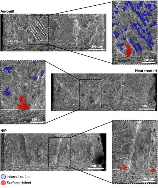
Fig. 11. Fractography of the V-notched samples tested at at σmaxof 400 MPa. The internal and surface defects shown by blue and red markers. The representative edge of the specimen is shown by white solid line.
sources of difference in fatigue behavior should be explored in the presence of defects and microstructure of the material after the post treatments. In this context, the presence of internal defects in the HT specimens is expected to reduce the fatigue strength and notch sensi-tivity. However, the experimental results represent higher fatigue strength and notch sensitivity of HT specimens compared to HIP counterparts.
In this scenario, the sensitivity of fatigue strength on the presence of internal defects can be evaluated using Atzori-Lazzarin diagram [60,61]. Considering an arbitrary defect with constant notch acuity of a/ρ in a material, the diagram evaluates ASED at fatigue limit as a function of defect size, a.Fig. 12shows a schematic illustration of this diagram. According to the diagram, defects which are smaller than a0in size, will not have an impact on fatigue limit (left plateau). For a defect larger than a*, linear notch mechanics can be used for obtaining the ASED at fatigue limit using stress concentration factor (right plateau). In the transition area between these two regions, the effect of defect on fatigue limit can be evaluated by means of linear elastic fracture me-chanics. The material length parameter, a0 [62]was reported to be related to the size of control volume obtained according to ASED cri-terion and for a material with Poisson’s ratio, ν of 0.3 under plane strain and plane stress conditions it is equal to 1.183R0 and 0.976R0, re-spectively [61]. Considering a plane strain condition for the tested specimens in this study, the material lengths of 0.592, 0.461, 0.580 mm were obtained for AB, HT, and HIP conditions. By comparing the maximum defect size in HT specimens (seeFig. 11) with the material length, in all cases, the defects fall in the plateau region for short cracks meaning that the presence of these defects will not have influence on the overall fatigue limit of HT specimens.
Considering the microstructural analysis, the approximate average grain sizes of 57 and 73 µm were obtained for HT and HIP specimens, respectively. The finer grain size in HT specimens results in higher ul-timate tensile strength and since the high cycle regime of fatigue is mainly controlled by the strength of the material, although some in-ternal porosities were present, higher fatigue strength was observed in these parts. Furthermore, due to fewer internal porosities, the notched HIP specimens may experience more localized plastic deformation ahead of the surface defects compared to the HT notched specimens. This results in a stronger shielding effect in HIP specimens and conse-quently leads to lower notch sensitivity of these parts.
As a rule, numerous factors namely the geometry of the part, pro-duction defects (i.e. surface roughness and internal defects), residual stress, and microstructure govern the overall behavior of AM compo-nents under quasi-static and fatigue loading conditions. Therefore, the application of a general failure criterion that is capable of taking into
account all the mentioned factors would be of great importance for the design of AM components. The volumetric local approaches for fatigue life assessment count for the mentioned factors by averaging all the material inhomogeneities in a control volume, resulting the metho-dology to be valid for the design of complex components produced by novel techniques such as AM. Three sets of SLM specimens were fab-ricated and post treated and the experimental results revealed different mechanical properties under quasi-static and fatigue loading condi-tions. Hence, three separate sets of theoretical analyses were under-taken using ASED criterion to evaluate fatigue behavior in the presence of a notch. Using the average SED as the key parameter to represent the fatigue data, three master curves were obtained for different case stu-dies. In all cases, the scatter index of the master curves was comparable to the value obtained for every single geometry. According to ASED criterion, only by performing fatigue tests on two sets of specimens namely smooth and notched specimens, it is possible to calculate the size of control volume, plot the master curve, and consequently obtain the driving equation of the master curve asW¯ =ANfB. By performing the theoretical analysis on AB, HT, and HIP specimens, the ASED con-stants were obtained for each case and reported inTable 4. According to this criterion, regardless of the geometry of notch, all fatigue data will follow the trend of the master curve. Therefore, the equation obtained from the reference specimens (i.e. smooth and notched) can be used to predict the fatigue behavior of specimens with other notch geometries. To conclude, considering the AM material as new input material for theoretical evaluation, it is possible to have an engineering prediction of fatigue life using the conventional local criteria such as ASED that take into account the effect of geometrical and material discontinuities.
5. Conclusions
The main aim of the current research was to evaluate the effect of two different post treatments namely heat treatment at 1150 °C in va-cuum and HIP on notch fatigue behavior of Co-Cr-Mo alloy produced by SLM process. Based on the experimental results and theoretical analysis, the following conclusions can be drawn:
(1) Performing heat treatment at 1150 °C in vacuum and HIP at 1150 °C–1020 bar resulted in the reduction of internal porosity in the SLM specimens from 1.25% in AB condition to 0.92% and 0.54% for HT and HIP specimens, respectively. Although the heat treatment process was performed in vacuum, the lack of fusion defects tend to reduce in size and number as a result of sintering the two faces of the defects during the process.
(2) In general, a ductility increase of 347 and 329% was observed for the SLM specimens subjected to heat treatment and HIP, respec-tively. This increased ductility is due to the prevalence of γ-phase. The ultimate tensile strengths of the post treated specimens were about 8 and 4% higher than that of as-built counterparts. (3) The presence of residual stresses together with a high number of
internal defects resulted in very poor fatigue behavior of as-built SLM parts. This aspect was significantly improved in the post treated parts, showing fatigue strength improvements of 180% and 136% for smooth specimens and 153% and 135% for notched 2a ρ σ0
1/
W
[m
m
3/Nmm
]
a [mm]
a
0a*
Linear notch mechanics Short cracks Long cracksNo sensitivity to defects
Fig. 12. Schematic representation of Atzori-Lazzarin diagram expressed as
in-verse ASED versus the defect/crack/notch length[61].
Table 4
Synthesis of the fatigue data by use of ASED.
Condition W¯ versus Nf
relationship
Tσ[Wohler
curve] T[Master curve]W(Tσ) R0[mm]
AB W¯ =594Nf0.641 Smooth: 1.64 V-notch:1.24 2.08 (1.44) 0.50 HT W¯ =49.14Nf0.346 Smooth: 1.24 V-notch:1.25 2.13 (1.46) 0.39 HIP W¯ =101.73Nf0.424 Smooth: 1.28 V-notch:1.20 1.48 (1.22) 0.49