2016
Publication Year
2020-11-25T12:02:32Z
Acceptance in OA@INAF
AGP (Astrometric Gravitation Probe) optical design report
Title
RIVA, Alberto; GAI, Mario; LANDINI, FEDERICO; Lazzarini, Paolo; Gallieni,
Daniele; et al.
Authors
10.1117/12.2232769
DOI
http://hdl.handle.net/20.500.12386/28536
Handle
PROCEEDINGS OF SPIE
Series
9907
Number
AGP (Astrometric Gravitation Probe) Optical Design Report
Alberto Riva
a, Mario Gai
a, Federico Landini
b, Paolo Lazzarini
c, Daniele Gallieni
c, Matteo
Tintori
c, Alberto Anselmi
d, Stefano Cesare
d, Deborah Busonero
a, Mario Gilberto Lattanzi
a,
Alberto Vecchiato
aa
INAF - Osservatorio Astrofisico di Torino, Strada Osservatorio, 20, I-10025 Pino Torinese
(TO), Italy
b
INAF - Osservatorio Astrofisico di Arcetri (Italy), Largo Enrico Fermi, 5, I-50125 Firenze
(FI), Italy
c
A.D.S. International Srl, via Roma, 87, I-23868 Valmadrera (LC), Italy
d
Thales Alenia Space Italia S.p.A., Strada Antica di Collegno, 253, I-10146 Torino, Italy
ABSTRACT
This paper describes the current opto-mechanical design of AGP, a mission designed for astrometric verification of General Relativity (GR) and competing gravitation theories by means of precise determination of light de-flection on field stars, and of orbital parameters of selected Solar System objects. The optical concept includes a planar rear-view mirror for simultaneous imaging on the CCD mosaic detector of fields of view also from the direction opposite to the Sun, affected by negligible deflection, for the sake of real time calibration. The precision of astrometric measurements on individual stars will be of order of 1 mas, over two fields separated by few degrees around the Sun and observed simultaneously. We describe the optical design characteristics, with particular reference to manufacturing and tolerancing aspects, evidencing the preservation of very good imaging performance over the range of expected operating conditions.
Keywords: AGP, Medium Mission, Diluted Pupil
1. INTRODUCTION
The Astrometric Gravitation Probe (AGP) is the concept of a space mission using high precision astrometry for determination of the light deflection and Solar System Ephemerides, related to the γ and β parameters of the Parametrized Post-Newtonian (PPN) formulation of Einstein’s General Relativity (GR) and competing gravitation theories.
An experiment located in space is able to overcome the limitations of the 1919 eclipse experiment[1], due to the short duration of the phenomenon, the high background flux from the solar corona, atmospheric disturbances and the limited number of accessible bright sources. We propose the concept of a dedicated mission for high precision astrometry in regions close to the Sun, in order to take advantage of the associated strong level of deflection. The space environment allows for large angle measurements unhindered by atmospheric turbulence, over a large time elapse. Averaging over several million stars, it is possible to improve on the limited individual measurement precision (due to the source magnitude and instrument resolution).
Light deflection reaches a peak value of 1”.74 at the solar limb, and decreases rapidly at increasing angular distance, and therefore, in order to estimate the γ parameter at the 10−6level and beyond, µas level measurements
of relative star positions are required at a few degrees from the Sun.
The design of the AGP instrument and operation is focused on minimization of systematic errors by enforcing measurement symmetry on the design of the instrument and of operation. Calibration on sky sources, which also benefits from imposed symmetry, allows identification and factorization of several error sources in the medium to long time scale.
Observation close to the Sun limb impose adoption of a coronagraphic system, aimed at rejection of the high photon flux from the solar disk and inner corona, with thorough control of the internal diffraction. A detailed study of such critical aspects is reported in the accompanying paper by Landini et al.[2].
The AGP concept has been previously presented in the form of either a small or medium class mission (i.e. GAME[3]), aimed at the measurement of the gravitational deflection of the light close to massive objects, in
particular the Sun.
2. OPTICAL DESIGN
In this section we describe the AGP optical design and its main features. The design is tailored onto the ESA-M4 call constraints (e.g. launcher, fairing, mass budget, etc.).
The implementation of the AGP differential measurement scheme is achieved by means of a dual-line-of-sight telescope with the addition of a rear-view mirror, i.e. a flat mirror using the non populated parts of the pupil mask (better described later) to feed the field of view in the anti-Sun direction. [see section 2.4]
Hereafter we will speak of optical channels (or branches) for the specific part of the system related to each line of sight. The initial part of the optical train is common to all optical channels, which are separated at the level of the third mirror and follow different (and symmetric) paths up to the common focal plane. In the following two sections we describe separately the two stages.
2.1 Telescope: common section
The telescope optical design is an evolution of the GAME [4][5] and ISAS [6] concepts, and it is derived from a
classical Korsch Three Mirror Anastigmatic configuration, e.g. the SNAP telescope [7].
The AGP telescope is designed with two channels, but it is compatible with up to four/eight channels. The two channels are pointing symmetrically to about +/- 1deg with respect to the optical axis of the telescope, which in nominal operation is set on the Sun. This corresponds to a base angle of 2 degrees. Each channel has a field of view of 16 arcminutes x 16 arcminutes. In some cases the two channels will be labelled conventionally as North (N) and South (S). Each channel has a similar and symmetric layout with respect to the telescope incoming beam (a.k.a. z-axis).
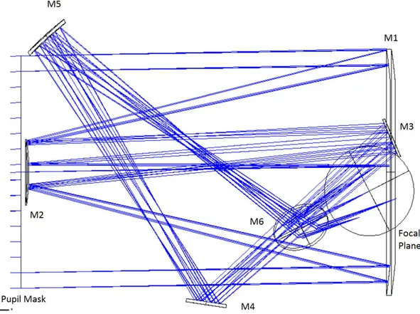
The optical design for the North channel is depicted in Figure 1.
The first stage of the instrument starts from the pupil mask and ends at the level of the fold mirrors (i.e. M3) that separate the two fields of view.
At the entrance, the pupil mask is the first element that the light encounters in the optical train. It is essentially a disk of diameter 1080.00 mm, with a set of 92 holes of diameter 21.4 mm, drilled in three coronae differently populated as shown in Figure 3.
After the mask, the light travels for 1.75 m and reaches the first mirror (M1). It is an annular concave mirror with external diameter 1148.26 mm and internal diameter 760.0 mm, with 92 holes of diameter 48.0 mm, placed in front of each elementary aperture on the pupil mask as shown in Figure 3. Their function is to dump to space the photon flux from the Sun disk; their size is defined in order to cope with the beam divergence that occurs in 1.75 m.
The beams from the desired field of view are collected by the primary mirror, and sent to the M2 mirror. M2 is a convex mirror of diameter 309.08 mm, directing the optical path toward the central region of M1, where the two channels are picked up by the folding mirrors (M3, one per channel). The two M3s are tilted symmetrically with respect to the optical axis.
Details on Mask, M1, M2, and M3 prescriptions are resumed in Table 1. Figure 4 shows the path of both channels at the same time (blue-green).
M5 M1 M3 M2
\\\ -
----\...:,/
'
Pupil Mask M4 Focal PlaneFigure 1. Optical layout of AGP for the single channel.
Table 1. Table of the most important parameters of optical path of each channel. All values are expressed in [mm].
Element Diameter Radius Conic Distance to next element Mask 1080.00 flat 0 1750.00 M1 1148.26 -4367.56181 -0.99265207 -1730.00 M2 309.08 -1045.77804 -1.65031622 1760.00 M3 200.00 flat 0 -1000.00 M4 180.00 flat 0 1650.00 M5 220.00 -1340.96793 -0.71077101 -1280.00 M6 240.00 flat 0 860.00
2.2 Telescope: individual channels
In this section we describe the optical path of each channel (North-South). As mentioned, the nominal configu-ration of each channel is symmetric with respect to the z axis.
After field pick-up on M3, the beam is further folded by M4. It is a fold mirror of diameter 180.00 mm, bending the beam to the off axis mirror M5. M5 is an off-axis mirror with diameter 220.00 mm and prescriptions given in Table 1.
The beam reflected by M5 is bent by M6 in the plane perpendicular to the z axis (Figure 5) toward the focal plane. M6 is a fold mirror of diameter 240.00 mm; its placement is anti-symmetric between channels, since its task is to combine the light coming from the two fields into a single focal plane.
Pupil
Mask 40 20 0 -20 -40 -40 -20 0 20 40Figure 2. 3D Optical layout of AGP.
Figure 3. Scheme of the 92 holes drilled in pupil mask (left) and in M1 mirror (right).
2.3 Focal plane
The common focal plane ”re-combines” the two channels, providing a superposed image of the two fields of view (North-South), This superposition is exploited for calibration, crucial for the AGP measurements.
The focal plane of AGP will be fitted with a number of 32 CCDs (2k x 4k with pixel size of 10 micron). The mosaic has a complexity comparable to those of Gaia and Euclid. We foresee the presence of some proximity boards to drive the CCD and receive the output data, while the data processing unit will be positioned farther away in a Service module.
The optical quality of the entire system is described by Figure 6, where the spots of 16 arcminutes of North field of view are depicted, while Figure 7 show the Point Spread Function (PSF).
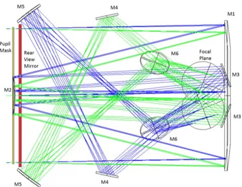
2.4 Rear-view mirror
The purpose of the rear-view mirror is to allow simultaneous measurements of the same stellar sample, in conditions of maximum and minimum deflection, in order to get rid of systematic errors. It takes advantages of
Pupil Mask M5 M4 M1 Focal Plane
.eviiAI
..;. .
--:''.
Figure 4. Optical layout of AGP for the two channels (North-South).
the non transmissive parts of the pupil mask, and it is fed by the apertures on the primary (M1) mirror, and its surrounding regions.
The rear-view mirror is a flat annular mirror with a set of 92 holes properly resized (diameter 30.0 mm), in order to provide clearance for the front beams crossing the pupil mask.
Figure 8 shows the position of the rear-view mirror in red. According to AGP measurements principles, star light coming from sources in the direction opposite to the Sun, are not affected by any deflection, and should improve the calibration issues of the experiment. The focal plane therefore images at the same time the two front and the two rear fields of view.
2.5 Tolerances
In this section we report on the values of the tolerances for the payload.
Table 2 lists the results of the tolerancing and sensitivity analyses performed on the basis of the spot size, that has to remain below the limit of the Airy disk (i.e. diffraction limit). Thanks to the differential mea-surement concept, the optical design requirements are satisfied even with a layout featuring rather reasonable manufacturing and alignment tolerance budget.
3. AGP STRUCTURAL DESIGN
The AGP structure is composed by the following elements.Focal Plane
M3 M4
Figure 5. Optical layout lateral (left) and frontal (right) view of AGP for a single channel.
Table 2. Table of the tolerances for the positioning of the AGP optical elements. Values are [mm] for translations (Tx Ty Tz) and [°] for rotations (RαRβ Rγ). All values must be intended as +/−.
Optical element Tx Ty Tz Rα Rβ Rγ Pupil Mask 0.01 0.01 0.10 0.10 0.10 0.10 M1 0.01 0.01 0.10 0.10 0.10 0.10 M2 0.01 0.01 0.10 0.10 0.10 0.10 M3 0.10 0.10 0.10 0.10 0.10 180.00∗ M4 0.10 0.10 0.10 0.10 0.10 180.00∗ M5 0.10 0.10 0.10 0.10 0.10 0.10 M6 0.10 0.10 0.10 0.10 0.10 180.00∗ Rear-Mirror 0.01 0.01 0.10 0.10 0.10 0.10 ∗
This number means that the item is substantially not affected by any variation of such degree of freedom
OBJ: 0.1340, 0.8660 (deg) IHA:-92.518, -597.960 mm 0117: -0.1340, 0.8660 (deg) OBJ: 0.1340, 1.1340 (deg) IHA: -94.791, -802.287 am OBJ: OBJ: -0.1340, .1340 (deg) 0.0000, 1.0000 (deg) IMA: 0.000, -697.763 mit IMA:94.791, -802.287 mm IMA: 92.518, -597.960 mm
Surface IHA: Focal Plane
0.5500
Spot Diagram
AGP Proposal
28/10/2014 Units are }un. Airy Radius: 22.48 }un
Field 1 2 3 4 5
RMS radius : 15.183 17.885 7.889 15.183 17.885
GEO radius : 22.783 37.345 16.187 22.783 37.345 Game 7.2.O.ZMX
Scale bar : 100 Reference : Chief Ray
Configuration 1
of 4
700 J00 -3000 -2000 0 1000 2000 3000 x [mas] -0.5 -2.5 300 200 100 0 100 200 300 -300 -200 -100 0 x [mas] 100 200 300 -0.5
Figure 6. AGP spots for one channel.
Figure 7. AGP Point Spread Function computed at 3000 degrees (left) and the same in zoomed in the central region computed at 9000 degrees (right).
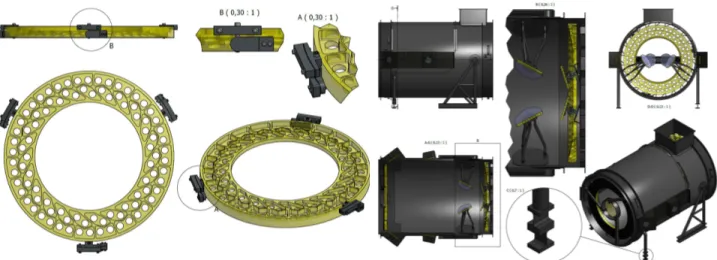
• Two circular extremities built from titanium (in white in the Figure 9)
• A large Carbon Fiber Reinforced Plastics (CFRP) central element (in red in the Figure 9) • A CFRP removable cover (in yellow in the Figure 9)
• Two CFRP open boxes, obtained by the same mold (in green in the Figure 9). These two elements provide the housing for the two M4s and M5s
• The four legs, built from stainless steel welded pipes (in cyan in the Figure 9). The extremities of three of the four legs end with flexible elements, to separate the thermal deformations of the AGP module from those of the satellite.
Pupil Mask
M2
Figure 8. Optical layout of AGP for two channels, with the rear-view mirror (in red).
The Carbon Fiber Reinforced Plastics (CFRP) components are glued to the titanium extremities. Reinforce-ments are used to cover all the glued joints. The removable cover is fixed by bolts to the other parts, the bolts are tightened to small metallic elements glued to the reinforced plastic. The mirrors are machine from Zerodur ceramic. The two larger optical elements, M1 and the rearview mirror, are light weighted. As a first and con-servative assumption, light weighting is obtained by milling only in the axial direction, also for the convex M1. This last point decrease the specific stiffness of the obtained structure, but makes the manufacturing process a lot easier. A good reference on the feasibility of such light-weighted mirrors which implements also the holes on the mirror surface as demanded by the proposed design is given by the ESO VLT-DSM reference body produced by Thales-SESO (i.e. Light weighted Zerodur reference body for the Adaptive Secondary Mirror of the VLT telescope. Diameter 1100mm, height 120mm, weight 45Kg.[8]).
M1, the rearview mirror and M2 could be held by three flexible interfaces glued at 120 degrees on the external flank of the glass. These flexible elements limits the print through of the thermal deformations in the titanium structures. No axial support is used for these three mirrors, because of the absence of dead weight effect; launch loads management is discussed in the analysis results. The support of these mirrors implements also a set of elements that allows the piston, tip and tilt adjustment. Three screws correct piston, tip and tilt, and the lateral support of the mirror is fixed to the titanium once that the optical element is aligned.
The mounting of the smaller mirrors M3, M4 and M5 is proposed to be made by a single support mechanism that corrects piston, tip and tilt. A spherical joint, driven by two screws, governs the tip and the tilt, and it is then fixed by a spherical clamping. A large central screw with a fixing nut governs instead the piston.
Two stainless steel tripods hold instead the two M6. The length of the three legs changes by moving telescopic elements, to regulate the piston, tip and tilt. The three legs split in two other legs near the interface to the glass, to add more stability.
M3s, M4s, M5s and M6s are glued in three points on their back. While M1, the rearview mirror, and M2 are glued on their side to the three lateral flexible supports. The weight of the AGP results 270Kg. Almost 100Kg is the weight of the mirrors alone.
4. AGP STRUCTURAL ANALYSIS
A first study of the structure has been performed by FEA. In the model the CFRP parts are modeled using an equivalent isotropic material. The interfaces to the mirror have a good level of detail and a first computation of the stress, even if still purely indicative, is thus realistic. The focal plane assembly is not present, its mass is
Figure 9. AGP structure elements
Table 3. FEM materials table
Material Density (Kg/m3) Young (GPa) Poisson CTE (micron/m ∗ K)
Zerodur 2530 90.3 0.2 0.01
Titanium (grade 5) 4100 105 0.33 14
CFRP (equivalent) 1750 90 0.3 1
Stainless steel 7850 200 0.3 14
anyhow negligible (10Kg) and its housing, inside a closed profile built from titanium, is not critical. Here after the properties used for the materials.
Maximum tensile stress has been computed for the Zerodur mirrors. Equivalent von Mises has been computed for the titanium and the steel parts. CFRP should be studied considering the shear and normal stress in the various layers, but, being an isotropic equivalent material used to reproduce the reinforced plastic behavior, Von Mises equivalent stress has been computed to have an indication of the criticality of stress in the carbon fiber main part.
The values of stress reported above must be taken as a preliminary indication by these initial analysises, in spite of the good level of detail in the FEM. The main point that emerges is that the solicitation levels are
B(0,30:1)
A(0,30:1)
Figure 10. Left: M1 and its flexible support. The mounting concept, shown in details A and B, is the same for the rearview mirror and M2. Note the light weighting milled glass. Right: Detail of assembly views of the unit
Table 4. Static analysis stress results summary.
1-g acceleration direction X Y Z
Glass (S1, Mpa) 2.4 2.1 4.5
Main structure (Von Mises, Mpa) 107 (CFRP) 89 (CFRP) 6.31 (titanium)
relatively high. Stress is considered safe in the Zerodur when it is below 10M P a, so the margin is very low and the design of the glass and of its interfaces must be accurately developed. Titanium, in its grade five alloy, is a very tough material, its yield stress is above 1000M P a, so the stress level is far from being a problem. CFRP must be studied more in detail, considering it’s orthotropic properties and the effect of the glue. Anyhow, it is not hard to predict that the Main CFRP element in the structure must be reinforced and its weight will increase. The legs of the telescope in the current configuration can withstand an acceleration of only a few Gs. Their design must be reviewed after that the load are defined in detail, especially the point regarding the separation of the thermal deformations of the AGP telescope from those of the satellite. This last point, regarding the thermal deformations, could be the main driving factor for the design of the flexible elements, whose presence must be carefully evaluated, because it has some serious drawback (stiffness and safety in primis). Results regarding the stress in the legs are not present here, because they are not representative of anything until some real load case is known and studied.
Some Eigen modes of the structure have been studied. The first modes are those significant for the relative motions of the mirrors inside the telescope. As it is valid for the stress, the Eigen modes involving the flex of the four legs are not significant. The interface between the telescope and the satellite must be reviewed, but the design of this part it is everything but a technical challenge. Currently, the first Eigen mode, with the telescope on the legs, is at only 10Hz, as it is visible in the image below.
5. CONCLUSIONS
The present paper summarizes the Optical Design for the AGP mission, whose main goal is the measure of positions of stars for light deflection and high precision solar system dynamics. It is designed through the diluted pupil concept and beam combining of two fields separated by few degrees around the Sun, with constraints of the Vega launcher. The design shows a good optical quality over the two 16’ x 16’ fields, and good tolerancing. The initial analysis presented in this document shows that the proposed concept of the AGP telescope is a viable base in terms of structural performances and initial mass budget for the development of the telescope design.
0o0'0 aL86£'S- L884Z Sa4968'S 9a9451'1 9,611'I 9a6£BZ'Z 9aL848'Z 9a4£1Y£ 9aZ8L6'£ WV9a6ibSb £f21 418UZ1/81 1 :awil ed:yu s s a1lç lednuud wnwxeyd ssailS iednuud wnwixey.l T80M.M.N83
Figure 11. Tensile stress in the glass for 1G along Z. Max stress is 4.5M P a
ACKNOWLEDGMENTS
The activity described in this paper is supported by the Italian Space Agency through contract I/058/10/0 and 2014-025-R.1.2015 to the italian National Institute of Astrophysics.
REFERENCES
[1] Dyson, F. W., Eddington, A. S., and Davidson, C., “A determination of the deflection of light by the sun’s gravitational field, from observations made at the total eclipse of may 29, 1919,” in [Philosophical Transactions of the Royal Society of London. ], A, Containing Papers of a Mathematical or Physical Character 220, 291–333 (1920).
[2] Landini, F., Riva, A., Gai, M., Baccani, C., Focardi, M., and Pancrazzi, M., “Stray light evaluation for the astrometric gravitation probe mission,” in [Optical and Infrared Interferometry and Imaging V ], Proc. SPIE 9907, 9907–149 (2016).
[3] Gai, M., Vecchiato, A., Ligori, S., Sozzetti, A., and Lattanzi, M. G., “Gravitation astrometric measurement experiment,” Experimental Astronomy 34, 165–180 (Oct. 2012).
[4] Gai, M., Vecchiato, A., Ligori, S., Riva, A., Lattanzi, M. G., Busonero, D., Fienga, A., Loreggia, D., and Crosta, M. T., “Gravitation astrometric measurement experiment (game),” in [Optical and Infrared Interferometry III ], Proc. SPIE 8445, 844513 (2012).
[5] Gai, M., Riva, A., Busonero, D., Vecchiato, A., Lattanzi, M. G., Gallieni, D., Lazzarini, P., Guglieri, G., Musso, I., and Navone, P., “Game/isas development status,” Proc. SPIE 9150, 91501I (2014).
[6] Gai, M., Fienga, A., Lattanzi, M. G., Riva, A., Vecchiato, A., Gallieni, D., Chaillot, S., Ligori, S., and Loreggia, D., “Isas: interferometric stratospheric astrometry for solar system,” in [Ground-based and Airborne Instrumentation for Astronomy IV ], Proc. SPIE 8446, 84464G (2012).
[7] Sholl, M. J. and et al., “SNAP Telescope,” Optical 5487, 1473–1483 (Oct. 2004). [8] “http://www.eso.org/public/announcements/ann1056/,”