A 1.7 GHz Fractional-N Frequency Synthesizer
Based on a Multiplying Delay-Locked Loop
Salvatore Levantino, Member, IEEE, Giovanni Marucci, Student Member, IEEE, Giovanni Marzin,
Andrea Fenaroli, Carlo Samori, Senior Member, IEEE, and Andrea L. Lacaita, Fellow, IEEE
I. INTRODUCTION
F
REQUENCY synthesizers based on the phase-locked loop (PLL) have a stringent tradeoff between integrated phase noise and dissipated power. Furthermore, this compromise is directly affected by the typical noise/power tradeoff of voltage-controlled oscillators (VCOs) [1]. For this reason, high-perfor-mance applications such as wireless frequency generation still rely on PLLs based on LC oscillators [2]–[5], which have better noise/power compromise than ring oscillators. Unfortunately, monolithic inductors do not benefit from technology scaling.Manuscript received April 27, 2015; revised July 26, 2015; accepted August 20, 2015. Date of publication September 14, 2015; date of current version October 27, 2015.
S. Levantino, C. Samori, and A. L. Lacaita are with the Politecnico di Milano, 20133 Milano, Italy (e-mail: [email protected]; [email protected]; [email protected]).
G. Marucci and A. Fenaroli were with the Politecnico di Milano, and are now with Qualcomm, Inc., San Diego, CA 92121 USA (e-mail: [email protected]; [email protected]).
G. Marzin was with the Politecnico di Milano, and is now with Blue Danube Systems, Warren, NJ 07059-2706 USA (e-mail: [email protected]).
Color versions of one or more of the figures in this paper are available online.
Fig. 1. Block diagram of a conventional multiplying DLL (MDLL).
Additionally, when more synthesizers on the same die must op-erate simultaneously in nearby bands (e.g., in carrier aggrega-tion), the electromagnetic coupling among VCO coils causes unwanted spurious tones in the spectra. This impairment has been recently counteracted by means of both elaborated cali-bration techniques [6], and suitable shapes of inductor coils [7] that reduce coupling but compromise quality factor.
For all these reasons, ring oscillators would be more desir-able than LC ones for radio transceiver design in scaled CMOS technologies. Thus, methods and schemes to aggressively filter or cancel out the phase noise of ring oscillators are being inves-tigated. Remarkable steps in this direction are the feed-forward cancellation schemes introduced in [8] and [9]. Most likely, LC oscillators will continue to be needed in integrated transceivers for wireless cellular standards. However, ring oscillators com-bined along with those techniques will be potentially employed as local oscillators in systems requiring moderate spot noise levels but tight integrated noise (e.g., high-bit-rate WLANs, or clocking of high-resolution data converters).
An effective way to significantly reduce the phase noise of a ring oscillator without appreciably increasing its power consumption is to rely on the so-called recirculating or multi-plying delay-locked loop (MDLL) [10]–[17]. This architecture schematically shown in Fig. 1 overcomes the typical limi-tations of PLLs in terms of noise-filtering bandwidth. In an MDLL, a multiplexed ring VCO let in the clean edges of the low-frequency reference signal (ref) and discards periodically the noisy edge of the oscillator. The reference edge is typically selected by means of a pulsed sel signal. While the phase noise
Fig. 2. Signal waveforms for the MDLL in Fig. 1: (a) ideal case, (b) case of PD time offset , (c) case of dithering the divider modulus from to .
of a free-running oscillator integrates indefinitely [18], [19] and the phase noise of a VCO closed into a PLL is filtered out within its bandwidth (inevitably set well below the reference frequency [20]), the periodic refreshing of the signal edge in the MDLL substantially limits jitter accumulation. As rigorously demonstrated in [14], [21], [22] (using alternative approaches) and intuitively described in [23], the output phase noise of the MDLL is given by the (discrete-time) first difference of the phase noise of the free-running VCO, sampled at the refer-ence rate . Thus, the output phase spectrum is given by filtering the spectrum of the free-running VCO via a first-order high-pass-shaped transfer function, with pole located at about
and high-frequency gain equal to 3 dB.
As a result, the phase noise of the free-running VCO in an MDLL is filtered out within a bandwidth much wider than in a typical PLL. This difference leads to the superior performance of MDLLs in terms of integrated jitter and dissipated power. Note that the same effect of wideband filtering of VCO phase noise is obtained by using the so-called injection locking PLL (IL-PLL), where a sub-harmonically injection-locked oscillator is enclosed in a PLL loop [24]–[31]. Unfortunately, MDLLs (as well as IL-PLLs) have two well-known limitations. First, the output frequency can only be changed by integer multiples of the reference frequency. The few attempts to extend MDLLs and IL-PLLs to fractional- synthesis have achieved just coarse frequency resolution [32], [33], preventing their use in prac-tical RF systems. The second problem is the large determin-istic jitter, or equivalently the large reference spur, which is mainly caused by the phase offset of the phase detector. Known solutions to the latter issue typically require additional hard-ware, increasing power consumption and silicon area. They en-tail either the realization of an additional feedback loop de-tecting the time offset and retiming the injected pulse [13], [24], [26]–[28], or the adoption of techniques aiming to decouple the feedback of the PLL loop from the reference injection (such as the dual-pulse oscillator in [14], [34], or the dual loop in [29]).
This paper describes the first published fractional- MDLL, achieving low jitter and power. Fractional- operation is ob-tained by inserting an automatically calibrated digital-to-time converter on the reference path. Deterministic jitter is mini-mized by adopting an automatic cancellation of the time offset that eliminates the main source of reference spur with little extra hardware. The paper is organized as follows: In Section II, the operating principle and the key issues of the classical MDLL are briefly recalled. Section III illustrates the proposed fractional-MDLL. Section IV describes the technique to automatically cal-ibrate the time offset. The overall implementation and the key building blocks are described in Section V. Section VI presents the measured results and, finally, the conclusions are drawn in Section VII.
II. MULTIPLYINGDLL BACKGROUND
The system in Fig. 1 without phase detector and integrator block is essentially a free-running ring oscillator periodically “realigned” by the signal ref. In fact, the pulser generates a pulse signal sel once every rising edges of the out signal (being an integer number), which allows the multiplexer to inject the
ref edges into the ring VCO. Since, in general, the free-running
frequency of the ring VCO, , differs from , the injec-tion of ref causes a periodic phase error in the signal out, with period . The larger the offset of from , the larger is the phase error, and the more powerful is the spu-rious tone in the output spectrum at offset from the carrier. This issue is in principle solved by the tuning loop in Fig. 1 [10], [11]. A phase detector (PD) senses the phase error between the reference signal and the frequency-divided output, and drives an integrator that provides the VCO tuning voltage. Thus, at steady state, the loop tunes the VCO, so that the output frequency is times the reference frequency ( ), and aligns the positive edges of ref and out, as shown in Fig. 2(a). We are as-suming, for the sake of clarity, zero time delay in the frequency divider. On the other hand, the periodic injection of ref causes a
falling edge of out after (being the output period), because of the odd number of inverting delay stages in the ring VCO. The resulting out in Fig. 2(a) is an ideal periodic waveform with no phase modulation, and, thus, no unwanted spurs in the spectrum. In contrast to a conventional PLL, the filter of the tuning loop is a simple integrator, and does not re-quire a stabilizing zero [10], [17]. This comes from the fact that the periodic injection of the reference signal into the ring VCO eliminates the intrinsic integration from the tuning voltage to the output phase. In other words, if a step signal is applied at the tune node, the excess output phase of the VCO will not di-verge, being periodically realigned by ref. Nevertheless, thanks to the integrator after the PD, the phase error between ref and div is always zero, even when differs from the free-running frequency of the VCO. In practice, like in a type-II PLL, there is no static phase error.
However, in contrast to a PLL, the time (or phase) offset at the input of the PD causes a spurious tone in the MDLL output spectrum at from the carrier, or, equivalently, a
determin-istic component of jitter [13], [14], [17]. The time offset is induced by both systematic and statistical mismatches between the two inputs of the PD, as well as by delay mismatches be-tween the two gates of the multiplexer in Fig. 1. The time offset causes a time shift equal to between ref and div, at steady state [see Fig. 2(b)]. In this case, the output period cannot be constant: the first period, , is longer than the average period , while the following ones, , must be shorter to get the correct average. The tuning loop sets the period of the
ring oscillator, , such that . The first
rising edge of out will be aligned to div, while the subsequent falling edge of out will occur seconds after the ref edge. Thus, . Combining the two previous equations,
we get . As a consequence,
the output excess phase [that can be seen as the phase error between out and the ideal out without offset, shown in gray in Fig. 2(b)] goes from zero to about
(for large values) and, then, decreases linearly reaching again zero after . This sawtooth shape of gives rise to a reference spur in the output spectrum.
Beside the offset problem, the use of the classical MDLL is bounded to integer- clock multiplication only. To explain this fact, we can analyze the signal waveforms in Fig. 2(c), where the modulus of the frequency divider in Fig. 1 is varied from to ( ) at every second reference cycle, and, for the sake of simplicity, the PD has zero phase offset. Thus, the average
output period is (being ).
Similarly to a fractional- PLL, the div signal is not aligned to the ref signal, but it exhibits a periodic phase error. However, in contrast to a fractional- PLL, the periodic injection of the ref edge into the ring VCO causes the subsequent falling edge of out to occur after . As sketched in the diagram in Fig. 2(c), this time shift induces and phase errors in the out signal, whose values can be as large as and . As a result, the output spectrum would be totally degraded by fractional spurs.
III. FRACTIONAL-N MULTIPLYINGDLL
Fig. 3 shows a simplified block schematic of the proposed fractional- MDLL. The synthesizer has a mostly-digital
ar-Fig. 3. Block diagram illustrating the operating principle of the proposed frac-tional- MDLL.
chitecture, where the phase error is detected and digitized by a time-to-digital converter (TDC), processed by a digital accu-mulator, and applied to the digital tuning input of a multiplexed ring-type digitally-controlled oscillator (DCO). With respect to the analog MDLL, this digital architecture offers lower area oc-cupation and power consumption [17], as well as easy and ac-curate implementation of calibration schemes.
Besides, a digital modulator dithers the modulus control of the frequency divider, to achieve on average fractional-frequency division. As highlighted above, the periodic injec-tion of the reference signal into the ring DCO produces an ex-tremely large modulation of the output phase , giving rise to very high fractional-spur levels. Assuming a first-order , the phase modulation is within rad, and it would be even larger for higher order 's. This problem that is inherent to fractional- synthesis is caused by the induced phase delay between ref and div, whose value is proportional to the ac-cumulated quantization noise .
To eliminate this unwanted modulation, we introduce a dig-ital-to-time converter (DTC) in the reference path, which adds a delay to the ref signal, according to the input digital word , and generates a delayed version of the reference signal, ref1. The sequence is obtained as the accumulated quantization noise times a gain . In this way, if has a proper value, the phase delay between ref and div, induced by dithering, is removed from the reference signal. In practice, ref1 is realigned to div. The gain is regulated by an accumulator driven by the product between the error detected by the TDC, , and . This feedback loop sets , such that is uncorrelated with , or, in other words, such that the component of induced by quantization is cancelled out.
The resulting signal waveforms are shown in Fig. 4. Since the new reference signal injected into the ring DCO, ref1, is perfectly aligned to div, no phase modulation of the out signal is produced, and no fractional spur is ideally generated in the output spectrum. As the quantization error is cancelled out via the DTC, it does not need to be converted by the TDC of the MDLL. Hence, a single-bit TDC can be employed to reduce
Fig. 4. Signal waveforms for the MDLL in Fig. 3.
power consumption and improve the jitter/power efficiency of the synthesizer [3].
In practice, the DTC has finite time resolution and, in gen-eral, nonlinear relationship between its control word and the time delay introduced. As a result, the cancellation of quan-tization error will be imperfect, giving rise to a residual modu-lation . An ideally linear -bit DTC would scale down the output excess phase shown in Fig. 2(c) by a factor of , leading to a residual within rad (i.e., for a first-order modulator). Nonlinearity in the DTC has the same impact of TDC nonlinearity in a digital PLL. In both cases, nonlinearity affects the reference signal path, and ultimately produces output spurs. Simulations and simple intu-itive models, [35], suggest that the integral nonlinearity (INL) has to be lower than one LSB, to keep the spurs induced by non-linearity below those induced by finite resolution.
IV. TIME-OFFSETCANCELLATIONMETHOD
The second typical impairment of an MDLL is the time offset of the PD, and in general any time mismatch between the two reference paths. As we have already highlighted in Section II, this offset gives rise to significant reference-spur levels. To sub-stantially mitigate this problem, two modifications to the orig-inal MDLL in Fig. 1 are made, and the resulting block dia-gram is shown in Fig. 5. First, an additional DTC is introduced which adds a delay between ref1 and the input of the multi-plexed ring DCO, ref2. Besides, a digital de-multiplexer is in-serted at the output of the TDC, that allows diverting either to the loop filter or to an accumulator controlling the second DTC input word. If always feeds the loop filter, the second DTC just adds a fixed delay between ref1 and ref2, that, with no loss of generality, we can assume to be zero. In this case, the input-referred TDC time offset generates a static time error between ref1 and div, producing the output phase modula-tion already sketched in Fig. 2(b). Unfortunately, the TDC that measures at each reference edge produces a sequence with all the samples equal to zero (if we neglect noise). So, to cancel this offset , we need to first find a way to detect it.
To this purpose, we halve the rate of the sel signal, which gets close to . The resulting signal diagrams are shown in Fig. 6(a). Since the reference signal, ref2, is not injected into the ring DCO at every second cycle and the phase of out is not reset, the TDC is now able to detect the offset at every second sample. So, we divert the TDC output with odd
Fig. 5. Block diagram of the automatic correction of the time offset in the MDLL.
to the tuning loop, and the sequence with even to an accumulator. The output, , of such accumulator is then used to control the delay of the second DTC. As a result, when converges, the signal ref2 is automatically delayed by a time that nulls with even , or, in other words, the offset-induced time error. In this way, the reference spur is removed [36]. The signals after the convergence of the offset-cancellation loop are shown in Fig. 6(b).
The offset-cancellation loop continuously runs in the back-ground of the MDLL, so it is able to track any variation of the PD time offset. Note that, in this mode of operation (that can be denoted as half-rate mode), the reference edges are injected into the ring DCO at rate, so the filtering bandwidth of DCO phase noise is halved. It is still possible to switch back to the full rate of injection of the reference edges. In this mode, which can be denoted as full-rate mode, the sort signal is kept constant and the steady-state value of is frozen. The signal waveforms are shown in Fig. 6(c). In this mode, we recover the maximum filtering bandwidth of DCO phase noise, although we may need to periodically switch on the offset-cancellation loop, to track offset drifts.
In contrast to the offset-cancellation scheme in [13], which is based on a correlated double sampling technique, the pro-posed scheme does not require a precise multi-bit TDC that measures the time offset, but it can operate with a low-power single-bit TDC. In practice, the achieved offset cancellation is limited by DTC finite resolution. An -bit DTC with resolution
leads to a residual amplitude of the phase error equal to rad. Because of the single-bit TDC, the time needed to correct an offset is in the order of
clock cycles, which typically does not represent a limitation. V. IMPLEMENTATION
The overall synthesizer, embedding a single-bit (or bang-bang) TDC, is shown in Fig. 7. The MDLL is designed to synthesize an output frequency between 1.6 and 1.9 GHz, from a 50 MHz oscillator. To remove the phase-noise contri-bution of the multi-modulus frequency-divider, the output of the multiplexed ring oscillator is directly fed to the TDC input [17]. This choice saves power in the frequency divider, which is only used to derive the selection pulse sel for the ring DCO.
Fig. 6. Signal waveforms for the MDLL in Fig. 5: (a) half-rate mode, without offset cancellation, (b) half-rate mode, with offset cancellation, (c) full-rate mode, with offset cancellation.
Fig. 7. Block diagram of the implemented fractional- MDLL.
Both the automatic cancellation of the quantization error and the TDC offset, discussed in the previous sections, are implemented using digital standard cells and automatic synthesis tools. The first algorithm applies the same delay correction on the two paths via the coarse DTC (common to both paths) and the common mode signal applied to the two fine DTC blocks. On the other hand, the TDC offset correction is applied differentially at the input of the fine DTC of the two paths. This guarantees concurrent operation of the two calibration loops, similarly to what happens in a fully differential operational amplifier, where common mode and differential mode feedbacks operate concurrently. Note that
any time mismatch between the two fine DTC blocks is not a concern, since it has the same impact as TDC time offset, and will be corrected by the offset cancellation loop as well.
The three control loops: (i) frequency tuning, (ii) offset can-cellation, and (iii) quantization-error cancellation operate simul-taneously and start up at the same time. Frequency tuning has a fast time constant (about 1.3 s), while the two calibration loops have a time constant of about 30 s, leading to an overall settling time from startup of about 150 s. The MDLL can be switched from full-rate to half-rate mode by relying on the mode input. When mode is asserted, the MDLL is in half-rate mode: the div signal rate is halved, and div is used to control the demultiplexer
Fig. 8. Schematic of the single-bit time-to-digital converter [37].
following the TDC. Doing so, the demultiplexer diverts every second sample of to the accumulator of the offset-cali-bration loop. On the contrary, when the mode signal is zero, the MDLL is in full-rate mode: div has the reference rate and every sample of is delivered to the tuning loop.
A. Time/Digital Converter
As already mentioned, the TDC is implemented as a single-bit TDC, which saves considerable power and area with respect to a multi-bit converter. The circuit schematic shown in Fig. 8 con-sists of the cascade of two CMOS latches in master-slave config-uration. A non-overlapping clock generator provides the clock phases to the two latches, to reduce kickback noise and limit flip-flop hysteresis [37]. The additional inverters between the latches increase isolation, so to further reduce hysteresis. The TDC drains about 62 from the 1.2-V supply, and it con-tributes to a flat phase noise of dBc Hz (referred to the MDLL output).
The asymmetry between the input paths of the TDC is the cause for a typical systematic time offset of about 9.6 ps, which is dominant over statistical mismatches. The time offset varies from 2.7 to 13.7 ps across the voltage supply range (1.1–1.3 V), and from 10.2 to 8.1 ps across the temperature range (0–125 ). Zero systematic offset (in typical conditions) can be achieved by employing a modified sense-amplifier flip-flop, as in [38]. However, in this case the power consumption would be much larger because of the static DC current. Moreover, the random offset and its variation over corners as well as the mismatches in the DCO multiplexer, would still force to employ an offset calibration circuit.
B. Multiplexed Ring DCO
The quantization introduced by the single-bit TDC, together with the DCO truncation error, may potentially generate limit cycles and, thus, spurs in the output spectrum [39]–[41]. To avoid them, the DCO resolution must be such that the power of
Fig. 9. Circuit schematic of the multiplexed ring DCO.
Fig. 10. Circuit schematic of the pulser and signal diagrams.
the deterministic truncation noise is lower than the true-random phase noise. The circuit schematic of the multiplexed-ring DCO is illustrated in Fig. 9. Five delay cells are closed in a
Fig. 11. Block diagram of circuits driving the frequency divider and the DTC converter: (a) Divider modulator, (b) Adaptive pre-distorter.
loop by means of a pass-transistor multiplexer. The delay cells employ a pseudo-differential topology [13], while frequency tuning is achieved by means of nMOS current starvers. A segmented tuning scheme is used to improve phase noise, increase maximum achievable frequency and reduce layout complexity. Coarse tune, which covers a frequency range between 1.3 and 2.4 GHz, is obtained by turning on and off 63 thermometer-coded nMOS transistors in each half of delay cell. A frequency-locked loop, not shown in figure, controls in the background the coarse tune, and helps speed up the locking transient of the MDLL. DCO fine tune is realized by means of an 8-bit DAC controlling the gate voltage of an nMOS transistor. The achieved resolution is about 500 kHz/bit. The DAC is implemented as a string of thermometer-coded poly-silicon resistors of about 90 . To further refine frequency resolution, a first-order modulator, clocked by the ref signal, drives the DAC input, and a 1 MHz pole set by a first-order RC filter at the DAC output help suppress the quantization noise. The multiplexed ring DCO dissipates about 1.4 mA, and exhibits SSB phase noise of 123.5 dBc Hz at 10 MHz offset from the carrier at 1.6 GHz.
Fig. 10 illustrates the pulser circuit along with the signal di-agrams. The pulser generates a periodic pulse signal sel and drives the selection input of the DCO multiplexer, which re-places an edge of the signal travelling in the DCO with a refer-ence edge, every output periods. To work properly, the pulses of sel must be centered on the DCO signal edge to be replaced. Since the tuning of the delay stages acts just on the pull-down network, the time offset between positive and negative outputs of the delay cell varies over the synthesized channel frequen-cies. To avoid this dependence, the negative edges of two sub-sequent signals of the delay line, and , both generated by the pull-down networks, are used as start/stop triggers for the rising/falling edges of sel. Two cascaded flip-flops sampling div guarantee the occurrence of the sel falling edge only after its rising edge. On the other hand, the NOR gate ensures that the
falling transition of sel occurs only after the reference edge has been allowed to enter the delay line.
C. Digital/Time Converter
As described in the previous sections, the DTC needs to cancel both the time offset of the TDC and the quantization noise induced by the dithering the frequency-divider modulus. So, the DTC range must accommodate both compo-nents. The driving the divider is a MASH 1–1 modulator, whose schematic is shown in Fig. 11(a). Therefore, the induced quantization error at the output of the divider is as large as two output periods, (i.e., 1.25 ns for the lowest output frequency, 1.6 GHz). The TDC offset and the statistical mis-matches between the two inputs of the DCO multiplexer are lower than about 20 ps.
On the other hand, DTC resolution must be lower than about 500 fs (about 12 equivalent bits), and the INL lower than one LSB, to get residual level of reference and fractional spurs below dBc. Moreover, being in a feedback loop, the DTC needs to have a monotonic characteristic. These linearity constraints over the wide dynamic range are combined with the requirement of sharp signal edges for low jitter. Thermometer coding guarantees monotonicity. However, the random mismatch of the unity delay piles up along the DTC characteristic. So, the RMS value
of the INL is , being the number of
bits and the RMS value of [42]. Thus, should be kept below few percent of the LSB in a 12-bit DTC. This requirement would be tight, as the required LSB is in the order of hundreds of femtoseconds. A simple increase of the size of unity delay elements should be compensated by a proportional increase of current consumption, to maintain the same slope of the voltage waveforms.
To reduce power and area occupation, the DTC is instead split into a coarse and two fine blocks, and an adaptive pre-distortion of DTC input word, , is adopted (Fig. 7). The adaptive pre-distortion relies on the technique described in [35] and shown
Fig. 12. Circuit schematic of the DTC converter: (a) coarse section, with tri-state delay element, and (b) fine section.
schematically in Fig. 11(b). Instead of simply multiplying by one gain, is mapped from the set of integer numbers
into the set . Thus, the
non-linear delay characteristic, , of the DTC is linearized from to , when the DTC is driven by the set of coeffi-cients . The resulting characteristic is the function in Fig. 11(b). To automatically estimate the -th coefficient in the background, the error , detected by the TDC when the signal , is integrated in the -th accumulator. Mean-while, the other ( ) accumulators integrate zero. In this fashion, every will converge to a value that minimizes the error due to the nonlinearity of the DTC characteristic. To reduce hardware, the adaptive pre-distorter is implemented with 16 accumulators. In this way, the will provide a piece-wise linear approximation of the inverse function of the DTC characteristic.
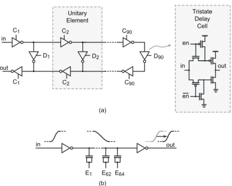
Fig. 12 shows the transistor-level implementation of the DTCs. The coarse DTC is implemented as a digitally control-lable delay line, which employs 93 unitary delay elements. Each delay element is made of tri-state inverters and allows to digi-tally shortening or lengthening the delay line. In simulations, the delay line covers a typical full-scale range from 320 to 2770 ps, with resolution of about 26 ps. This allows covering the required range of with margin over process, temperature and voltage (PVT) variations. Current consumption and phase noise vary linearly across the delay range. In the middle of the range, DC current is 330 , flat phase noise is estimated to be equal to dBc Hz (referred to MDLL output), while the supply sensitivity, obtained from transistor-level simula-tions, is about 1.6 ns/V. The 8-bit fine DTC that is cascaded to the delay line is instead implemented as an inverter stage loaded by an array of thermometer-coded MOS varactors and a subsequent CMOS inverter stage restoring the sharpness of the voltage edges at the output. The full-scale range of the fine
Fig. 13. Die photograph.
DTC covers with wide margin the LSB of the coarse one, while its resolution is equal to about 400 fs, in nominal conditions. The current consumption is 60 per each fine DTC, and their contribution to the output phase noise is dBc Hz.
VI. EXPERIMENTALRESULTS
Fig. 13 shows the photograph of the chip, fabricated in a 65 nm CMOS process [43]. The size of the die is pad limited to 1 mm . For this reason, a decoupling capacitance of about 900-pF is included in the die (left side), and about 800 pF is spread over the standard-cell-based digital section (right side),
Fig. 14. Measured spectrum for a fractional- channel: (a) disabling DTC cor-rection, (b) enabling cancellation of noise and disabling offset correction, and (c) enabling both cancellation of noise and offset correction. which is not optimized for density. When the circuit is em-bedded in a system on chip, a voltage regulator to avoid coupling
Fig. 15. Reference-spur level, measured hand-tuning the fine-DTC control word: 25 MHz (squares) and 50 MHz (diamonds) spur levels in half-rate mode; 50 MHz spur (circles) in full-rate mode.
among blocks can be used in place of most of the decoupling ca-pacitance, with negligible area occupation [17]. The digital core area, excluding the capacitance, is only about 0.04 mm . The analog blocks occupy about 0.05 mm , whose main contribu-tors are the DTC (25%) and the crystal reference oscillator (XO, 20%). Thus, the total core area of the synthesizer is 0.09 mm . The synthesized frequency covers the 1.6–1.9 GHz range with a frequency resolution of about 190 Hz from the 50 MHz reference. The total power consumption (excluding pad drivers and XO) is 3.0 mW from a 1.2 V supply, when a fractional-channel is synthesized. When the circuit synthesizes an in-teger- channel, the coarse DTC is bypassed. So, its dissipation is reduced to a negligible value, and the overall power drops to about 2.4 mW.
The impact of both the cancellation of noise and TDC time offset via the DTC was experimentally assessed. Fig. 14(a) shows the output spectrum of the MDLL, when the dithers the divider modulus and the two algorithms are disabled. The large modulation visible in the spectrum is related to the mechanisms described in Fig. 2(c), which would prevent the use of a plain MDLL for fractional- synthesis. The spec-trum measured after enabling the cancellation of noise is shown in Fig. 14(b). The noise is substantially cancelled, but the reference spur level is still about dBc, and a dBc fractional spur at 720 kHz offset and its harmonics are visible in the spectrum. The fractional spurs, which are typically caused by the nonlinearity in the path from injection point to output, were not expected from simulations, and they may be ascribed to unwanted coupling between the harmonics of the input reference and the sensitive nodes of the ring DCO and of the DTC. As the offset cancellation is enabled in full-rate mode, the refer-ence-spur level drops at dBc, as shown in Fig. 14(c), while the level of fractional spurs is unaffected. This result further sustains the hypothesis of a parasitic coupling at the origin of the residual fractional spurs. Offset cancellation is verified also opening the calibration loop and manually sweeping the fine DTC input in Fig. 5. The measured reference-spur level is reported in Fig. 15. In half-rate mode, the injection rate is halved to 25 MHz. So, the spur induced by the TDC offset lies at 25 MHz, and its level (squares in Fig. 15) goes from to dBc, sweeping the fine-DTC input word. In the same experimental conditions, the 50 MHz spur level (diamonds) is
Fig. 16. Measured phase noise of the free-running multiplexed ring DCO. TABLE I
PERFORMANCECOMPARISONWITHINDUCTOR-LESSFRACTIONAL- FREQUENCYSYNTHESIZERS
about 6 dB lower than the 25 MHz one (far from the minimum of the curve), which is consistent with level of the second harmonic of the sawtooth phase error described in Fig. 2(b). Instead, the minimum level of the 50 MHz spur saturates at about dBc, revealing an unwanted coupling of the 50 MHz reference signal. In full-rate mode, the 50 MHz spur follows the level measured in half-rate mode and reaches a minimum of dBc1. So, even in the full-rate mode, the minimum
reference-spur level is not limited by the DTC resolution, but by unwanted coupling of the reference to the output signal. If the voltage supply is varied across the 1.1–1.3-V range, the minimum of the curves in Fig. 15 is shifted at different values of the DTC input word, but it shows the same behavior.
Fig. 16 displays the measured phase noise of the free-run-ning multiplexed ring DCO. The phase noise extends up to about 1.2 MHz offset, the value at 100 kHz is about dBc Hz, while phase noise at 10 MHz offset is about dBc Hz. The MDLL phase noise plots measured for integer- ( ) and fractional- channel ( ) 1The measured level of the reference spur is lower than the value reported in [43], and it was obtained improving the ground shielding of the die bonded on the test board.
are shown in Fig. 17. Those measurements were compared against numerical simulations in Fig. 18. Perfect agreement is obtained for the integer- case in Fig. 18(a). The phase noise of the free-running DCO, filtered up to about 25 MHz (i.e., ), and that of the TDC at low frequency dominate MDLL noise. Instead, the phase noise of the reference path, mainly induced by the fine DTC (shown in the plot), is negligible. In the fractional- case shown in Fig. 18(b), the reference noise introduced by the DTC is higher, as discussed above. How-ever, even this component does not fully justify the measured spectrum. The peak measured at high offset frequency may be ascribed to an imperfect cancellation of the quantization noise. A residual -quantization-noise component (shown in the same plot), 52-dB lower than the theoretical spectrum, may justify the measured spectrum.
The plot in Fig. 19 reports the RMS jitter integrated from 30 kHz to 30 MHz, as a function of the synthesized frequency. The jitter ranges between 0.47 and 0.55 ps for integer- chan-nels (main plot), and between 1.15 and 1.4 ps for fractional-ones (inset). To compare this realization against other frac-tional- , inductor-less, frequency synthesizers, we adopt the figure of merit (FoM) typically used for PLLs [1]. The FoM is
TABLE II
PERFORMANCECOMPARISONWITHMDLLS ORINDUCTOR-LESSIL-PLLS
Fig. 17. Measured phase noise of the MDLL: (a) integer- , (b) fractional-channel.
defined as , being the integrated
jitter variance in squared seconds and the dissipated power, expressed in milliwatts. The plot in in Fig. 20 reports versus , where the solid lines are obtained at constant FoM. The
Fig. 18. Comparison of measured and simulated phase noise for (a) integer- , and (b) fractional- channel.
FoM achieved by the presented MDLL of about dB (in the worst channel case) outperforms by several dBs the other published works. Table I summarizes and the main performance of the MDLL and compares it with the best published frac-tional- inductor-less PLLs. Table II compares this work with other integer- frequency synthesizers based on MDLLs or inductor-less IL-PLLs. The FoM of this work (ranging between and dB) outperforms previous works (excluding [17], [29] that benefit from a lower frequency-division factor)
Fig. 19. Measured jitter over integer- and fractional- channels.
Fig. 20. Jitter-versus-power plot of inductor-less fractional- frequency synthesizers.
at comparable level of reference spur, thanks to the low-power one-bit TDC and the offset cancellation scheme.
VII. CONCLUSION
This paper presented the design of the first fractional-MDLL. Cancellation of noise and TDC time offset is ob-tained thanks to the insertion of a automatically-regulated DTC on the reference path. The prototype synthesizes frequencies be-tween 1.6 and 1.9 GHz with 190 Hz resolution and achieves worst-case RMS integrated jitter of 1.4 ps at 3 mW power con-sumption and FoM of dB. The measured RMS jitter with integer- division is 0.47 ps at 2.4 mW power, which leads to a FoM of dB. In both cases, the level of the reference spur is about dBc. To the best of our knowledge, this circuit out-performs previously published, inductor-less fractional- syn-thesizers in terms of both jitter and power dissipation.
ACKNOWLEDGMENT
The authors wish to thank M. Zuffada and E. Temporiti of STMicroelectronics for supporting chip fabrication.
REFERENCES
[1] X. Gao, E. A. M. Klumperink, P. F. J. Geraedts, and B. Nauta, “Jitter analysis and a benchmarking figure-of-merit for phase-locked loops,”
IEEE Trans. Circuits and Systems II: Express Briefs, vol. 56, no. 2, pp.
117–121, 2009.
[2] X. Gao, E. Klumperink, G. Socci, M. Bohsali, and B. Nauta, “A 2.2 GHz sub-sampling PLL with 0.16 psrms jitter and dBc Hz in-band phase noise at 700 W loop-components power,” in IEEE
Symp. VLSI Circuits Dig. Tech. Papers, Jun. 2010, pp. 139–140.
[3] D. Tasca, M. Zanuso, G. Marzin, S. Levantino, C. Samori, and A. L. Lacaita, “A 2.9-to-4.0 GHz fractional- digital PLL with bang-bang phase detector and 560 integrated jitter at 4.5 mW power,” IEEE
J. Solid-State Circuits, vol. 46, no. 12, pp. 2745–2758, Dec. 2011.
[4] S. Levantino, G. Marzin, C. Samori, and A. L. Lacaita, “A wideband fractional- PLL with suppressed charge-pump noise and automatic loop filter calibration,” IEEE J. Solid-State Circuits, vol. 48, no. 10, Oct. 2013.
[5] P.-C. Huang, W.-S. Chang, and T.-C. Lee, “A 2.3 GHz fractional- di-viderless phase-locked loop with dBc Hz In-band phase noise,” in IEEE Int. Solid-State Circuits Conf. Dig. Tech. Papers, 2014, pp. 362–363.
[6] A. Mirzaei and H. Darabi, “Pulling mitigation in wireless transmitters,”
IEEE J. Solid-State Circuits, vol. 49, no. 9, pp. 1958–1970, Dec. 2014.
[7] L. Fanori, T. Mattsson, and P. Andreani, “A 2.4-to-5.3 GHz dual-core CMOS VCO with concentric 8-shaped coils,” in IEEE Int. Solid-State
Circuits Conf. Dig. Tech. Papers, 2014, pp. 370–371.
[8] S. Min, T. Copani, S. Kiaei, and B. Bakkaloglu, “A 90 nm CMOS 5-GHz ring-oscillator PLL with delay-discriminator-based active phase-noise cancellation,” IEEE J. Solid-State Circuits, vol. 48, no. 5, pp. 1151–1160, May 2013.
[9] M. Mikhemar, D. Murphy, A. Mirzaei, and H. Darabi, “A cancella-tion technique for reciprocal-mixing caused by phase noise and spurs,”
IEEE J. Solid-State Circuits, vol. 48, no. 12, pp. 3080–3089, Dec. 2013.
[10] S. Ye, L. Jansson, and I. Galton, “A multiple-crystal interface PLL with VCO realignment to reduce phase noise,” IEEE J. Solid-State Circuits, vol. 37, no. 12, pp. 1795–1803, Dec. 2002.
[11] R. Farjad-Rad et al., “A low-power multiplying DLL for low-jitter multigigahertz clock generation in highly integrated digital chips,”
IEEE J. Solid-State Circuits, vol. 37, no. 12, pp. 1804–1812, Dec. 2002.
[12] S. Ye and I. Galton, “Techniques for phase noise suppression in re-circulating DLLs,” IEEE J. Solid-State Circuits, vol. 39, no. 8, pp. 1222–1230, Aug. 2004.
[13] B. M. Helal, M. Z. Straayer, G.-Y. Wei, and M. H. Perrott, “A highly digital MDLL-based clock multiplier that leverages a self-scrambling time-to-digital converter to achieve subpicosecond jitter performance,”
IEEE J. Solid-State Circuits, vol. 43, no. 4, pp. 855–863, Apr. 2008.
[14] S. Gierkink, “Low-spur, low-phase-noise clock multiplier based on a combination of PLL and recirculating DLL with dual-pulse ring oscil-lator and self-correcting charge pump,” IEEE J. Solid-State Circuits, vol. 43, no. 12, pp. 2967–2976, Dec. 2008.
[15] T. Ali, A. Hafez, R. Drost, R. Ho, and C.-K. Yang, “A 4.6 GHz MDLL with dBc reference spur and aperture position tuning,” in IEEE
Int. Solid-State Circuits Conf. Dig. Tech. Papers, 2011, pp. 466–467.
[16] D.-W. Jee, D. Sylvester, D. Blaauw, and J.-Y. Sim, “A 0.45 V 423 nW 3.2 MHz multiplying DLL with leakage-based oscillator for ultra-low-power sensor platforms,” in IEEE Int. Solid-State Circuits Conf. Dig.
Tech. Papers, 2013, pp. 188–189.
[17] A. Elshazly, R. Inti, B. Young, and P. Hanumolu, “Clock multiplica-tion techniques using digital multiplying delay-locked loops,” IEEE J.
Solid-State Circuits, vol. 48, no. 6, pp. 1416–1428, Jun. 2013.
[18] J. A. McNeill, “Jitter in ring oscillators,” IEEE J. Solid-State Circuits, vol. 32, no. 6, pp. 871–872, Jun. 1997.
[19] A. A. Abidi, “Phase noise and jitter in CMOS ring oscillators,” IEEE
J. Solid-State Circuits, vol. 41, no. 8, pp. 1803–1816, Aug. 2006.
[20] F. M. Gardner, “Charge-pump phase-lock loop,” IEEE Trans.
Commun., vol. COM-28, no. 11, pp. 1849–1858, Nov. 1980.
[21] P. Maffezzoni and S. Levantino, “Phase noise of pulse injec-tion-locked oscillators,” IEEE Trans. Circuits Syst. I, vol. 61, no. 10, pp. 2912–2919, Oct. 2014.
[22] N. Da Dalt, “Jitter an analysis of phase noise in religned VCOs,” IEEE
Trans. Circuits Syst. II: Express Briefs, vol. 61, no. 3, pp. 143–146,
Mar. 2014.
[23] W. Deng, D. Yang, T. Ueno, T. Siriburanon, S. Kondo, K. Okada, and A. Matsuzawa, “A fully synthesizable all-digital PLL with inter-polative phase coupled oscillator, current-output DAC, and fine-reso-lution digital varactor using gated edge injection technique,” IEEE J.
[24] B. M. Helal, C.-M. Hsu, K. Johnson, and M. H. Perrott, “A low jitter programmable clock multiplier based on a pulse injection-locked oscil-lator with a highly-digital tuning loop,” IEEE J. Solid-State Circuits, vol. 44, no. 5, pp. 1391–1400, May 2009.
[25] J. Lee and H. Wang, “Study of subharmonically injection-locked PLLs,” IEEE J. Solid-State Circuits, vol. 44, no. 5, pp. 1539–1553, May 2009.
[26] C.-F. Liang and K.-J. Hsiao, “An injection-locked ring PLL with self-aligned injection window,” in IEEE Int. Solid-State Circuits Conf. Dig.
Tech. Papers, 2011, pp. 90–91.
[27] Y.-C. Huang and S.-I. Liu, “A 2.4-GHz subharmonically injection-locked PLL with self-calibrated injection timing,” IEEE J. Solid-State
Circuits, vol. 48, no. 2, pp. 417–428, 2013.
[28] I.-T. Lee, Y.-J. Chen, S.-I. Liu, C.-P. Jou, F.-L. Hsueh, and H.-H. Hsieh, “A divider-less sub-harmonically injection-locked PLL with self-ad-justed injection timing,” in IEEE Int. Solid-State Circuits Conf. Dig.
Tech. Papers, 2013, pp. 414–415.
[29] A. Musa, W. Deng, T. Siriburanon, M. Miyahara, K. Okada, and A. Matsuzawa, “A compact, low-power and low-jitter dual-loop injection locked PLL using all-digital PVT calibration,” IEEE J. Solid-State
Cir-cuits, vol. 49, no. 1, pp. 50–60, Jan. 2014.
[30] W. Deng, D. Yang, T. Ueno, T. Siriburanon, S. Kondo, K. Okada, and A. Matsuzawa, “A 0.0066 mm 780 W fully synthesizable PLL with a current-output DAC and an interpolative phase-coupled oscil-lator using edge-injection technique,” in IEEE Int. Solid-State Circuits
Conf. Dig. Tech. Papers, 2014, pp. 266–267.
[31] J.-C. Chien, P. Upadhyaya, H. Jung, S. Chen, W. Fang, A. M. Niknejad, J. Savoj, and K. Chang, “A pulse-position-modulation phase-noise-re-duction technique for a 2-to-16 GHz injection-locked ring oscillator in 20 nm CMOS,” in IEEE Int. Solid-State Circuits Conf. Dig. Tech.
Pa-pers, 2014, pp. 52–53.
[32] P. Park, J. Park, H. Park, and S. Cho, “An all-digital clock gener-ator using a fractionally injection-locked oscillgener-ator in 65 nm CMOS,” in IEEE Int. Solid-State Circuits Conf. Dig. Tech. Papers, 2012, pp. 336–337.
[33] S. Lee, S. Ikeda, H. Ito, S. Tanoi, N. Ishihara, and K. Masu, “An in-ductor-less injection-locked PLL with 1/2- and 1/4-integral sub-har-monic locking in 90 nm CMOS,” in IEEE Radio Frequency Integrated
Circuits (RFIC) Symp. Dig., Jun. 2012, pp. 189–192.
[34] D. Park and S. Cho, “A 14.2 mW 2.55-to-3 GHz cascaded PLL with reference injection and 800 MHz Delta-Sigma modulator in 0.13 m CMOS,” IEEE J. Solid-State Circuits, vol. 47, no. 12, pp. 2989–2998, Dec. 2012.
[35] S. Levantino, G. Marzin, and C. Samori, “An adaptive pre-distortion technique to mitigate the DTC nonlinearity in digital PLLs,” IEEE J.
Solid-State Circuits, vol. 49, no. 8, Aug. 2014.
[36] G. Marzin, A. Fenaroli, G. Marucci, S. Levantino, C. Samori, and A. L. Lacaita, “Spur cancellation technique for MDLL-based frequency synthesizers,” in Proc. Int. Symp. Circuits and Systems (ISCAS), 2013, pp. 165–168.
[37] N. Da Dalt, “Theory and implementation of digital bang-bang fre-quency synthesizers for high speed serial data communications,” Ph.D. dissertatiojn , Rheinisch-Westfälischen Technischen Hochschule Aachen, Aachen, Germany, 2007.
[38] M. Zanuso, P. Madoglio, S. Levantino, C. Samori, and A. L. Lacaita, “Time-to-digital converter for frequency synthesis based on a digital bang-bang,” IEEE Trans. Circuits Syst. I: Reg. Papers, vol. 57, no. 3, pp. 548–555, Mar. 2010.
[39] N. Da Dalt, “Linearized analysis of a digital bang-bang PLL and its va-lidity limits applied to jitter transfer and jitter generation,” IEEE Trans.
Circuits Syst. I, Reg. Papers, vol. 55, no. 11, pp. 3663–3675, Nov. 2008.
[40] M. Zanuso, D. Tasca, S. Levantino, A. Donadel, C. Samori, and A. L. Lacaita, “Noise analysis and minimization in bang-bang digital PLL,”
IEEE Trans. Circuits Syst. II, Expr. Briefs, vol. 56, no. 11, pp. 835–839,
Nov. 2009.
[41] G. Marucci, S. Levantino, P. Maffezzoni, and C. Samori, “Analysis and design of low-jitter digital bang-bang phase-locked loops,” IEEE
Trans. Circuits Syst. I, Reg. Papers, vol. 61, no. 1, pp. 26–36, Jan. 2014.
[42] C.-H. Lin and K. Bult, “A 10-b, 500-MSample/s CMOS DAC in 0.6 mm ,” IEEE J. Solid-State Circuits, vol. 33, no. 12, pp. 1948–1958, Dec. 1998.
[43] G. Marucci, A. Fenaroli, G. Marzin, S. Levantino, C. Samori, and A. L. Lacaita, “A 1.7 GHz MDLL-based fractional-N frequency synthesizer with 1.4 ps RMS integrated jitter and 3 mW power using a 1 b TDC,” in IEEE Int. Solid-State Circuits Conf. Dig. Tech. Papers, 2014, pp. 360–361.
[44] T.-K. Jang, X. Nan, F. Liu, J. Shin, H. Ryu, J. Kim, T. Kim, J. Park, and H. Park, “A 0.026 mm 5.3 mW 32-to-2000 MHz digital frac-tional- phase locked-loop using a phase-interpolating phase-to-dig-ital converter,” in IEEE Int. Solid-State Circuits Conf. Dig. Tech.
Pa-pers, 2013, pp. 254–255.
[45] X. Yu, Y. Sun, W. Rhee, and Z. Wang, “An FIR-embedded noise fil-tering method for fractional-N PLL clock generators,” IEEE J.
Solid-State Circuits, vol. 44, no. 9, pp. 2426–2436, Sep. 2009.
[46] A. Elkholy, A. Elshazly, S. Saxena, G. Shu, and P. K. Hanumolu, “A 20-to-1000 MHz peak-to-peak jitter reconfigurable multi-output all-digital clock generator using open-loop fractional dividers in 65 nm CMOS,” in IEEE Int. Solid-State Circuits Conf.
Dig. Tech. Papers, 2014, pp. 272–273.
[47] J. Liu, T.-K. Jang, Y. Lee, J. Shin, S. Lee, T. Kim, J. Park, and H. Park, “A 0.012 mm 3.1 mW bang-bang digital fractional- PLL with a power-supply-noise cancellation technique and a walking-one-phase-selection fractional frequency divider,” in IEEE Int. Solid-State
Cir-cuits Conf. Dig. Tech. Papers, 2014, pp. 268–269.
[48] Z. Shu, K. L. Lee, and B. H. Leung, “A 2.4-GHz ring-oscillator-based CMOS frequency synthesizer with a fractional divider dual-PLL archi-tecture,” IEEE J. Solid-State Circuits, vol. 39, no. 3, pp. 452–462, Mar. 2004.
[49] T.-K. Kao, C.-F. Liang, H.-H. Chiu, and M. Ashburn, “A wideband fractional-N ring PLL with fractional-spur suppression using spec-trally shaped segmentation,” in IEEE Int. Solid-State Circuits Conf.
Dig. Tech. Papers, 2013, pp. 416–417.
[50] M. S.-W. Chen, D. Su, and S. Mehta, “A calibration-free 800 MHz fractional- digital PLL with embedded TDC,” in IEEE Int.
Solid-State Circuits Conf. Dig. Tech. Papers, 2010, pp. 472–473.
[51] D.-W. Jee, Y. Suh, H.-J. Park, and J.-Y. Sim, “A 0.1- BW 1 GHz fractional- PLL with FIR embedded phase-interpolator-based noise filtering,” in IEEE Int. Solid-State Circuits Conf. Dig. Tech. Papers, 2011, pp. 94–95.
[52] R. K. Nandwana, T. Anand, S. Saxena, S.-J. Kim, M. Talegaonkar, A. Elkholy, W.-S. Choi, A. Elshazly, and P. K. Hanumolu, “A 4.25 GHz–4.75 GHz calibration-free fractional-N ring PLL using hybrid phase/current-mode phase interpolator with 13.2 dB phase-noise improvement,” in IEEE Symp. VLSI Circuits Dig. Tech. Papers, Jun. 2014.
[53] T.-H. Tsai, M.-S. Yuan, C.-H. Chang, C.-C. Liao, C.-C. Li, and R. B. Staszewski, “A 1.22 ps integrated-jitter 0.25-to-4 GHz fractional-N ADPLL in 16 nm FinFet CMOS,” in IEEE Int. Solid-State Circuits
Conf. Dig. Tech. Papers, 2015, pp. 260–261.
[54] C.-F. Liang and P.-Y. Wang, “A wideband fractional-N ring PLL using a near-ground pre-distorted switched-capacitor loop filter,” in IEEE Int.
Solid-State Circuits Conf. Dig. Tech. Papers, 2015, pp. 190–191.
[55] W. Deng, Y. Dongsheng, A. T. Narayanan, K. Nakata, T. Siriburanon, K. Okada, and A. Matsuzawa, “A 0.048 mm 3 mW synthesizable frac-tional- PLL with a soft injection-locking technique,” in IEEE Int.


![Fig. 8. Schematic of the single-bit time-to-digital converter [37].](https://thumb-eu.123doks.com/thumbv2/123dokorg/8262629.130093/6.888.212.832.84.815/fig-schematic-single-bit-time-digital-converter.webp)