UNIVERSITÀ DELLA CALABRIA
Dipartimento di Ingegneria Meccanica, Energetica e Gestionale
(DIMEG)
Dottorato di Ricerca in
Ingegneria Civile e Industriale
Ciclo
XXIX
Shape Memory Alloy connectors for Ultra High
Vacuum applications: a breakthrough for
accelerator technologies
Settore scientifico disciplinare
ING-IND/14
Coordinatore: Ch.mo Prof. Franco Furgiuele
Firma:_________________________
Supervisori/Tutor: Ch.mo Prof. Franco Furgiuele (UNICAL)
Firma:____________________
Ch.mo Dott. Cedric Garion (CERN)
Firma:____________________
Dottorando: Dott. Fabrizio Niccoli
Firma:______________________
ABSTRACT
The design of tight connections for ultrahigh-vacuum (UHV) systems is a key subject for vacuum technology. Design requirements become even more stringent when dealing with UHV beam-pipe coupling in high-energy particle accelerators, where reliability and safety are core issues. For this specific application, additional needs often arise: strict geometrical and/or space limitations, connection of dissimilar materials and installation in restricted access areas. The latter constraint is of major concern, especially in the new generation of high-energy particle accelerators such as the HL-LHC (High Luminosity Large Hadron Collider), which will be operational at CERN (European Organization for Nuclear Research) in 2026. Owing to the increased proton-beam intensity and luminosity of the HL-LHC, radioactivity will be higher at some points than in the present LHC. The radiation exposure time of the technical personnel in some critical areas will be strictly controlled and minimized. The use of standard ConFlat® flanges (CF) or quick connect ConFlat® flanges (QCF)
could result in significant design and operational/maintenance limitations. In particular, the mounting and dismounting of CFs are time-consuming due to the high number of bolts and lead to significant radiation doses incurred by operators. Conversely, QCFs can be installed more quickly, but they suffer from the requirement of more space and are unwieldy components comprising heavy stainless-steel chain clamps.
Within this framework, Shape Memory Alloys (SMAs) offer a unique possibility to generate tight connections and fast clamping/unclamping by remotely changing the temperature of the SMA junction unit; at the microscopic scale this occurs trough a reversible solid-state transformation between the parent austenitic phase and the product martensitic one. In this PhD work, SMAs were used to develop a new generation of vacuum tightening systems for accelerator beam-pipe coupling by exploiting their shape recovery capabilities and actuation principles. The proposed coupling system consists of a SMA ring and a sealing element to be placed at the SMA-vacuum chambers interface, i.e. a copper coating or a thin cylindrical aluminum/copper gasket. Commercial NiTiNb rings and NiTi sleeves ad-hoc developed by Intrinsic Devices Inc. (USA) based on CERN technical constraints were properly investigated. The rings show two-way shape memory effect remembering a contracted austenitic shape and an enlarged martensitic one. The thermomechanical properties of the selected SMAs were measured experimentally. The tightening performance of SMA rings, was studied for different values of the initial clearance between the SMA ring and the vacuum pipe. The contact pressure was estimated by both strain gauge (SG) measurements and by Digital Image Correlation (DIC), using an ad-hoc developed numerical
procedure. A novel design method was proposed that involves numerical results, obtained from Finite Element (FE) simulations and a literature vacuum sealing model. Leak tightness tests were carried out to assess the sealing performance of the of SMA-based prototype UHV chambers even after ageing at room temperature and repeated thermal cycles. Irradiation tests on SMA-based prototype vacuum chambers (SMA absorbed dose > 100 kGy) was performed at CHARM (Cern High energy AcceleRator Mixed field) facility at CERN and the functional and leak tightness performance of the couplings was successfully verified afterwards.
The main results revealed that the contact pressure is not significantly affected by the initial SMA ring-pipe assembly clearance due to the plateau in the stress-strain response of the material. Thermal dismounting and subsequent re-clamping is obtained by exploiting the two-way shape memory recovery capabilities of the alloys. Leak rate measurements showed that the constraints for UHV applications could be easily satisfied (leak rate < 10-10 mbar l s-1) even after multiple
thermal cycles; this opens the possibility of remotely clamping/unclamping the tight couplers by well-defined temperature variations.
The proposed SMA-based beam-pipe couplers can be installed without using any connection flange. They are smaller and lighter than CF and QCF devices currently used in UHV systems at CERN. These bolt-free SMA-based connectors could provide significant benefits in terms of installation-dismounting time, space occupancy, bi-material joining and, above all, possible remote thermal activation, obtainable, for example, with removable heating/cooling collars.
Based on these results, possible applications in CERN accelerators have already been identified. A first use has been proposed for the ISOLDE (Isotope Separator On Line DEvice). A second application is the vacuum system of the Large Hadron Collider (LHC) between the two high-luminosity experiments (ATLAS and CMS) and the beam focusing-defocusing quadrupole magnets (frequently called inner triplets). Moreover, particle collimators are also critical devices of accelerator equipment. In all these applications, high-energy particles induce a large radioactivity and, consequently, personnel access is restricted. The use of SMA rings with remote clamping-unclamping features could be beneficial to avoid contamination and irradiation of technical personnel. Finally, SMA coupling installations are already planned in the CLEAR test facility at CERN, which provides the electron beam for the Compact Linear Collider (CLIC) study.
SOMMARIO
La progettazione di dispositivi di collegamento meccanico per applicazioni in sistemi di ultra- alto vuoto (Ultra High Vacuum - UHV) è particolarmente complessa. I vincoli di progettazione diventano ulteriormente stringenti nel caso di sistemi di accoppiamento per i tubi a vuoto utilizzati negli acceleratori di particelle ad elevata energia, quale il Large Hadron Collider (HLC) del CERN, in cui affidabilità e sicurezza rappresentano requisiti fondamentali. In particolare, in queste applicazioni occorre spesso considerare le seguenti esigenze progettuali: vincoli di ingombro, connessioni multi-materiale e installazione in aree ad accesso limitato. Quest'ultima peculiarità diventa sostanziale in vista di una nuova generazione di acceleratori di particelle, l'HL-LHC (High Luminosity Large Hadron Collider), che sarà operativa al CERN nel 2026. HL-LHC è un progetto volto all'incremento della luminosità di LHC di un fattore 10 rispetto al valore di progetto. L’au e to dell’i te sità del fas io e del u ero di ollisio i delle particelle permetterà misure più accurate e l'osservazione di processi fisici rari, che avvengono al di sotto del livello di sensibilità della macchina attuale. Sfortunatamente, la radioattività sarà significativamente più alta in alcune aree critiche. Il tempo di esposizione alle radiazioni del personale tecnico dovrà essere strettamente controllato e limitato. Per queste ragioni, l'utilizzo di flange convenzionali ConFlat® (CF) o di flange a collegamento rapido (Quick ConFlat, QCF) potrebbe causare importanti limitazioni sia nella progettazione dei sistemi UHV oltre che nelle operazioni di manutenzione in esercizio. In particolare, il montaggio e lo smontaggio di delle flange CF richiedono molto tempo a causa dell'elevato numero di bulloni; ne conseguono dosi di radiazione per i tecnici significativamente elevate. I sistemi QCF, invece, possono essere installati più velocemente, ma si tratta di componenti realizzati mediante pesanti catene in acciaio e, pertanto, risultano molto ingombranti.
In questo contesto, le leghe di memoria di forma (Shape Memory Alloys - SMAs) offrono la possibilità unica di generare connessioni di tenuta caratterizzate da montaggio/smontaggio rapido sfruttando un recupero di forma vincolato attivabile termicamente da remoto. Su scala microscopica, questo avviene attraverso una trasformazione reversibile allo stato solido tra la struttura austenitica e martensitica, nota come trasformazione martensitica termo-elastica. Nell’a ito delle attività di dottorato, le SMAs sono state utilizzate per sviluppare una nuova generazione di sistemi di serraggio per i tubi a vuoto degli acceleratori del CERN, sfruttando le loro capacità di recupero di forma e i peculiari principi di attuazione. Il sistema di accoppiamento proposto è costituito da un anello SMA e da un elemento deformabile con funzione di tenuta
da collocare all'interfaccia tra l’anello SMA e le camere da vuoto; questo può essere un rivestimento in rame o una guarnizione cilindrica sottile in alluminio/rame. Lo studio è stato condotto sia su anelli commerciali in lega nichel-titanio-niobio (NiTiNb) che su manicotti in lega nichel-titanio (NiTi) sviluppati ad-hoc da Intrinsic Devices Inc. (USA) in accordo ad opportune specifiche funzionali definite dal CERN. Gli anelli investigati manifestano memoria di forma a due vie ricordando una geometria contratta in fase austenitica ed una espansa in fase martensitica. Le proprietà termomeccaniche delle leghe selezionate sono state misurate sperimentalmente. La pressione di serraggio esercitata dagli anelli SMA è stata valutata per diversi valori del gioco iniziale tra l’ele e to a e oria di for a e i tubi a vuoto. Sono state analizzate differenti o figurazio i geo etri he dell’i terfa ia a ello “MA/tu i a vuoto. I carichi radiali dovuti all’azio e delle “MA sulle camere da vuoto sono stati stimati sia attraverso misure estensimetriche (Strain Gage - SG) che con tecniche di correlazione digitale di immagine (Digital Image Correlation - DIC), utilizzando una procedura numerica sviluppata ad hoc. È stato inoltre proposto un metodo di progettazione basato su un nuovo parametro di prestazione della tenuta a vuoto. Quest’ulti o è stato definito sulla base dei risultati numerici ottenuti attraverso simulazioni agli elementi finiti (Finite Element - FE) e un modello di conduttanza di letteratura. Sono state condotte diverse prove sperimentali di tenuta a vuoto su prototipi di camere connesse attraverso manicotti SMA. Tali prove sono state effettuate anche dopo invecchiamento a temperatura ambiente e cicli termici ripetuti. Alcuni prototipi sono stati esposti a intense radiazioni ionizzanti (dose assorbita> 100 kGy) presso la facility CHARM (Cern High Energy AcceleRator Mixed Field) del CERN e il comportamento funzionale degli accoppiamenti, in termini di tenuta a vuoto e smontabilità, è stato successivamente verificato. I principali risultati delle analisi effettuate hanno rivelato che la pressione di contatto non è significativamente influenzata dal gioco iniziale tra il manicotto SMA e le camere da vuoto a causa del plateau nella risposta tensione-deformazione del materiale. Lo smontaggio termico e il successivo ri-clampaggio sono stati ottenuti sfruttando la memoria di forma a due vie delle leghe. Le prove di tenuta a vuoto hanno mostrato che il vincolo per applicazioni UHV risulta soddisfatto (leak rate<10-10 mbar l s-1) anche dopo diversi cicli termici.
In conclusione, è stato dimostrato che i connettori SMA proposti possono essere installati senza l’utilizzo di flange di collegamento; sono compatti e più leggeri dei dispositivi CF e QCF attualmente utilizzati nei sistemi UHV al CERN. Inoltre, no prevede do l’utilizzo di ullo i di serraggio, riducono sensibilmente i tempi di installazione e smontaggio. Possono essere sfruttati per la realizzazione di giunzioni bi-materiale e, soprattutto, permettono l’attivazione ed il controllo da remoto, ottenibile, ad esempio, attraverso collari di riscaldamento/raffreddamento rimovibili.
Sulla base di questi risultati sono già state identificate possibili applicazioni negli acceleratori del CERN. È infatti stato proposto un primo utilizzo per ISOLDE (Isotope Separator On Line DEvice). Una seconda applicazione è il sistema a vuoto del Large Hadron Collider (LHC) tra i due
esperimenti ad alta luminosità (ATLAS e CMS) ed i magneti quadrupoli utilizzati per la focalizzazione/de-focalizzazione del fascio. Le particelle ad alta energia inducono alti livelli di radioattività in prossimità dei collimatori e conseguentemente l'accesso al personale è fortemente limitato; l'utilizzo di anelli SMA con funzionalità di installazione e disaccoppiamento a distanza potrebbe essere utile per evitare la contaminazione e l'irradiazione del personale tecnico in queste aree. I fi e, l’utilizzo dei o ettori SMA è già previsto nella CLEAR test facility al CERN. Quest’ulti a fornisce il fascio elettronico per gli studi relativi al Compact Linear Collider (CLIC). Il vantaggio principale dei manicotti SMA, in questa particolare applicazione, sarebbe relativo ai loro limitati ingombri.
ACKNOWLEDGMENTS
Being part of both Dr. Chiggiato’s group at CERN a d Prof. Furgiuele’s group at UNICAL has been a real privilege as well as a vibrant and exciting experience.
I am heartily grateful to Paolo and Cedric who have given me the chance to deepen my knowledge and skills in the creative and cosmopolite environment of one of the most prestigious research center in the world. Their guidance has been immensely valuable and encouraging; their competence and professionalism have been excellent examples for me. Thank you very much for all your suggestions and support!
I am enormously thankful to Prof. Furgiuele for his constant availability as well as his unique frankness. Thanks a lot, Prof., for having given me the possibility to work in your outstanding research group!
Very special thanks go to Prof. Carmine Maletta, I had the privilege of being guided by. He is an excellent professor and a marvelous person. The enthusiasm he shows for his work is contagious and motivational. The words needed to show the extent of my gratitude and esteem toward him would not fit this page so I have to summarize my recognition by means of the following word: Grazie!
Finding friends among your colleagues/officemates is usually not that easy: Emanuele, Giulia, Caterina, Piergiorgio at UNICAL and Marco (Caro Marco!) at CERN have demonstrated to me how lucky I have been (for Emanuele and Giulia: I will never forget our lovely summertime in the lab. Thanks a lot! Mpuuuu!)
Warm thanks go to Renato, Diego and Ernesto for having endured me in the lab. Their support has been great as well as their entertaining company.
Similarly, I want to thank Erik along with Pawel, two colleagues I had the pleasure to collaborate with, at CERN; their kindness and professionality have been outstanding.
I am greatly thankful to the whole UNICAL fa ily o posed y Prof. Pagnotta, Luigi, Marco, Giovanna, Piergiorgio, Pietro, Chiara; having fun while working is such a gift! Many thanks guys for the amusing time we have had!
All the people I have met at CERN during the last three years have greatly contributed to my professional and personal growth. I have encountered amazing scientists and I have found good friends and colleagues like Alessandro, Fabrizio, Luca, Marco, Giorgio, Max, Gabi, Miriam, Stefano, Luis, Alexis, Javier, Ida, Roberto, Julien, Rafa and many more: working at CERN and living in Geneva have been great mainly thanks to the lovely moments spent together.
I want to heartily tha k y old ut gold pre ious frie ds fro Cose za. I do not want to list them because they perfectly know who they are. Thank you, guys, for the quality of the time we continue to spend together! Lastly, I would like to thank my family for all their sacrifices, their love and constant support in all my pursuits. Mamma, Papà, Fede: Grazie di tutto!
CONTENTS
1 Introduction 1
1.1 High energy physics at CERN 1
1.2 Vacuum systems at CERN 2
1.3 The need of remote operations at CERN 3
1.4 Needs of quick and compact connection systems for beam pipe couplings 5
1.5 Research objectives 5
1.6 Thesis outline and contributions 6
2 Basics of vacuum technology for particle accelerators 8
2.1 Introduction 8
2.2 Basic notions on vacuum technology 8
2.3 Gas kinetics 10
2.4 Conductance in free molecular flow 11
2.4.1 Conductance of an orifice 11
2.4.2 Conductance in a complex geometry 13
2.5 Pumping speed 14
2.6 Pressure profile calculation 16
2.7 Pumps description 17
2.8 Sources of gas within the vacuum system 17
2.8.1 Thermal outgassing 17
2.8.2 Dynamic outgassing 22
2.8.3 Permeation 23
2.8.4 Vaporization 24
2.8.5 Gas leaks in vacuum systems 24
2.8.6 Virtual leaks 25
2.9 Pump down curve and pressure limits of vacuum systems 25
3 Joining techniques in vacuum technology for particle accelerators 28
3.1 Introduction 28
3.2 Materials for vacuum chambers and flanges 29
3.3 Material for gaskets 29
3.4 Joining technologies 32
3.4.1 Permanent connections 32
3.4.2 Detachable connections 33
3.5.1 The surface roughness influence in leaking 42
3.5.2 Conductance of the Leak Path 42
3.5.3 The sealing curve and the effect of the bakeout 45 3.6 Beam pipe coupling systems at CERN: reliability aspects and limitations 47
4 Advanced materials for non-conventional coupling technologies: Shape Memory Alloys 51
4.1 Introduction 51
4.2 SMA general features 51
4.2.1 Brief Overview and History 51
4.2.2 Crystallographic Structure: martensitic transformation 53 4.2.3 Characteristic Temperatures and Phase Transformations 59
4.2.4 One Way Shape Memory Effect 62
4.2.5 Two Way Shape Memory Effect 63
4.2.6 Pseudoelasticity 65
4.2.7 A More General Overview of Shape Memory Behavior 67
4.2.8 NiTi-based Shape Memory Alloy 68
4.2.9 Near-equiatomic nickel-titanium system 69
4.2.10 Alloys with narrow hysteresis 73
4.2.11 Alloys with wide Hysteresis: the NiTiNb system 73
4.2.12 Copper and Iron based Alloys 76
4.2.13 Applications of SMAs 77
4.3 Constrained recovery mechanism of SMA: principle and applications 85
4.3.1 The generation of recovery stress 85
4.3.2 Main features of SMA-based constrained recovery applications 88 4.3.3 Classification of SMA constrained recovery applications 89
4.3.4 Advantages of SMA couplers and fasteners 95
4.3.5 Commercial SMA coupler and fasteners 96
4.3.6 Recent developments in SMA couplings 97
5 SMA-based beam-pipe connectors: SMA characterization, design and experimental methods 99
5.1 Introduction 99
5.2 SMA selection 100
5.3 SMA ring-steel pipe coupling process 103
5.4 SMA thermo-mechanical characterization methods 104
5.4.1 Strain gauge measurements 105
5.4.2 Digital Image Correlation measurements 107
5.5 SMA-based connectors design methods 115
5.5.1 SMA–pipe coupling geometry 115
5.5.2 Thermo-mechanical constitutive model for SMAs 117 5.5.3 Finite element model of the SMA-steel ring coupling process 118
5.5.4 SMA-steel pipe coupling optimization methods 121
5.5.5 A novel sealing performance parameter 124
5.6 Leak tightness tests 126
5.7 Irradiation tests on SMA prototype vacuum chambers 128
5.7.1 Radiation damage 129
5.7.2 Experimental and numerical methods 130
6 NiTiNb-based beam-pipe couplers for Ultra-High vacuum pipes 132
6.1 Introduction 132
6.2 Stress free thermal recovery of NiTiNb rings 132
6.3 Thermal activation of NiTINb-steel rings coupling 133
6.4 Local analysis by DIC 136
6.5 Thermal dismounting of NiTiNb-steel rings coupling 137
6.6 Contact pressure analysis in NiTiNb-steel pipe couplings 140
6.7 Leak tightness performance calculation 146
6.8 Leak tightness performance measurement 149
7 NiTi-based beam pipe couplers for Ultra-High vacuum pipes 151
7.1 Introduction 151
7.2 NiTi characterization 151
7.3 Stress-free and stress-applied tests of NiTi rings 152 7.4 Leak tightness measurement and assembly dismounting 156
7.5 Outgassing measurements of NiTi Alloys 159
7.6 Irradiation on SMA prototype vacuum chambers: post-irradiation results 160
8 Conclusions and perspectives 166
Bibliography 170
LIST OF FIGURES
Figure 1.1: CERN accelerator complex 1
Figure 1.2: Cross section of a LHC dipole 2
Figure 1.3: Application of ALARA and intervention operation restrictions in CERN facilities 4
Figure 2.1: Schematic drawings of components installed in series (top) and parallel (bottom) 11
Figure 2.2: Schematic drawing of two volumes at different pressures p1 and p2 divided by a
small orifice of surface A 12
Figure 2.3: Schematic drawing of two vessels connected by a complex duct. 13
Figure 2.4: Meshes used for Monte Carlo simulation of the MKQVL kicker of SPS.
The second picture shows molecular tracks (in green) generated by Molflow+ code. 14
Figure 2.5: Schematic drawings of component of a gas flow restriction of conductance C
interposed between a pump of pumping speed S and a vacuum vessel. 16
Figure 2.6: Scheme of the main types of vacuum pumps. 17
Figure 2.7: Fluxes for a general surface 18
Figure 2.8: Water vapour outgassing rate of stainless steel and aluminium
after four different surface treatments 19
Figure 2.9: Pressure evolution in an aluminum chamber. The pressure increase represents the
beginning of the bakeout. The pressure drop follows the system cooling down to room
temperature 20
Figure 2.10: Schematic diagram of the system used to measure outgassing rates q by
the throughput method. The two vacuum gauges (or RGAs) G1 and G2 are used to measure the
pressure drop (P1-P2) across the conductance C. 21
Figure 2.11: Release of the gas accumulated long over a certain amount of time. 22
Figure 2.12: Interpolation of gas quantities accumulated over different times. 22
Figure 2.13: Technical scheme of the system used in the laboratory of CERN 23
Figure 2.14: Rate limiting step during the pumping of a vacuum chamber 27
Figure 3.1: Klein Flange – KF (left) and ISO-K flange (right) 35
Figure 3.2: Shear seals principles (flanges in light grey, gasket in dark grey) 36
Figure 3.3: “ he ati depi tio of a Balzer fla ge the ele e t i the zoo ed
area is the 0.08 mm aluminum gasket) 36
Figure 3.4: Schematic drawings of the CF flange system (left) and cross section of
the knife edge (right). 37
Figure 3.5: The Helicoflex seal (Handbook of vacuum science and technology) 38
Figure 3.6: Seal detail of a diamond cross section aluminum seal between flat flanges (left)
and of standard CF flanges using corner-crush gasket(right) 38
Figure 3.7: Sealing principle of a Swagelok ® tube fitting
Figure 3.8: Schematic drawings of the QCF® flange system proposed by Vacom® (left)
Figure 3.9: Schematic drawings of 3 quick disconnect flanges: EVAC CF flange assembly (left),
EVAC CFX flange assembly (center) and EVAC ISO flange assembly (right). 40
Figure 3.10: Seal cross-section: (a) without gasket- not leak tight;
(b) with inserted gasket- leak tight 40
Figure 3.11: Dimension of the seal: (a) The interface contact annulus; (b)a typical leak path;
(c) the surface contact (machined surface); (d) single paths on the surface;
(e) loaded interface contact 42
Figure 3.12: a typical sealing curve 45
Figure 3.13: Yield stress a d You g s odulus ariatio ith te perature for opper a d
Stainless steel 46
Figure 3.14: An example of (a) Conflat ® (CF) and
(b) Quick disconnect Conflat® (QCF) connection systems 47
Figure 4.1: (a) Austenite and (b) Martensite lattice structures 54
Figure 4.2: Free energy trends, as a function of the temperature, for the
austenitic () and martensitic (’) structure 55
Figure 4.3: transformation (sit) and plastic (NP) shear stress as a function of the temperature. 55
Figure 4.4: Bidimensional scheme of the phase transformation from a) austenite to d) martensite.
As shown in the figure, the atomistic movement is short enough to avoid chemical bonds rupture 56
Figure 4.5: (a) atomistic slip e (b) twinnning. 57
Figure 4.6: representation of a twin boundary. 57
Figure 4.7: an applied stress generates a movement of the martensitic twin boundaries.
The result is a macroscopic geometric shape variation. 58
Figure 4.8: Temperature-induced phase transformation of an SMA without mechanical loading 59
Figure 4.9: Schematic of the SMA detwinning under an applied stress 59
Figure 4.10: Schematic of the shape memory effect (SME) of an SMA showing the unloading
of a detwinned structure and the subsequent shape recovery by
heating (transforming to austenite) under no loading condition 59
Figure 4.11: Hysteretic behavior obtained, under a constant applied stress, by heating and
cooling a sample. The tangent lines allow to get the characteristic transformation temperatures 60
Figure 4.12: SMA stress-strain response obtained at different operating temperatures:
(a) T > MD, no martensitic phase transformation is recorded, the material is characterized by a stable austenitic structure and exhibits the typical behavior of a common engineering metal. (b) Af< T < MD the material shows the pseudo-elastic behavior. (c) T < Mf the material exhibits
(c) a stable martensitic structure (detwinning process) 61
Figure 4.13: stress-strain-temperature data exhibiting the OW-SME for a typical NiTi SMA 63
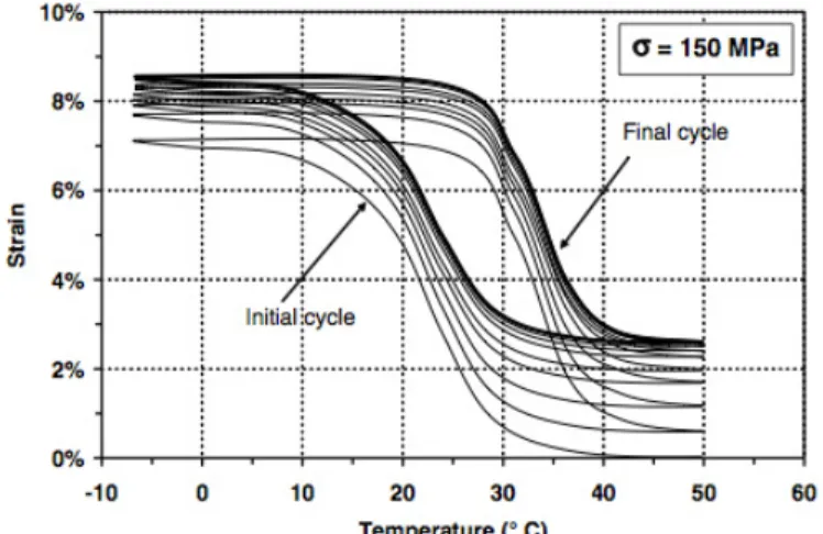
Figure 4.14: Thermal cyclic loading of a NiTi shape memory alloy under constant load of 150 MPa,
example of constrained cycling of deformed martensite training 65
Figure 4.15: Pseudoelastic response of an as-re ei ed NiTi ire ith Af = ◦C, tested at a
te perature of ◦C. Also sho is the sta ilized pseudoelasti hysteresis loop after y les.
Example of pseudoelastic cycling training 65
Figure 4.16: a typical the stress–strain curve of a pseudoelastic SMA (Lagoudas, 2008) 66
Figure 4.18: Nickel-titanium phase diagram. The region around 50 at% Ni
is expanded in Figure 4.19. 69
Figure 4.19: Phase diagram between TiNi (B2) phase and metastable Ti3Ni4 precipitates.
Phase equilibrium between TiNi and TiNi3 is also shown 70
Figure 4.20: Differential scanning calorimetry plot demonstrating two-phase transformation
on cooling via the R-phase. 71
Figure 4.21: Ms temperature as a function of Ni content for binary NiTi alloys. Different symbols
represent data from different authors. The solid line is given by thermodynamic calculations 72
Figure 4.22: The microstructures of (a) Ni50Ti49Nb1, (b) Ni50Ti47Nb3,
(c) Ni49.6Ti45.9Nb4.5 and (d) Ni47Ti44Nb9 alloys 74
Figure 4.23. Comparison of stress and strain limits between new developed SMA and
other engineering materials 77
Figure 4.24: SMA application categories: free recovery (a), constrained recovery (b),
actuation/work production (c) and pseudoelasticity (d) 77
Figure 4.25: Nu er of “hape Me ory Alloy arti les a d pate ts y years-group 78
Figure 4.26: Global market forecast for smart materials for 2010–2016 79
Figure 4.27: Boeing variable geometry chevron 80
Figure 4.28. The stress versus strain relationship for superelastic nitinol, stainless steel 81
Figure 4.29: Orthodontic application of SMAs: (a) Nitinol braces used for alignment purposes
in dental applications. (b) A schematic showing a NiTi drill used for root canal surgery 82
Figure 4.30: Cardiovascular devices that utilize the engineering properties of SMAs:
(a) Top view (above) and side view (below) of the Simon filter in the deployed configuration (b) A self-expanding Nitinol stent shown in the deployed configuration (above) and
constrained state (below) 83
Figure 4.31: NiTi thermovariable rate springs applications 84
Figure 4.32: Schematic depiction of the uniaxial constrained shape recovery mechanism:
the stress-strain relationship (a), strain-temperature relationship (b)
and stress-temperature relationship (c). 85
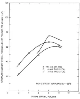
Figure 4.33: maximum recovery stress r for NiTi as a function ofunl (initial strain) 87
Figure 4.34: (a) maximum recovery stress r for NiTiFe as a function ofc (unl =7.3%) and
(b) maximum recovery stress r for NiTiFe obtained for different substrate compliance 87
Figure 4.35: Principle of operation of a SMA pipe coupler 90
Figure 4.36: A cut away of an installed SMA coupling 90
Figure 4.37: Cryoflare ® and Cryolive® couplings 91
Figure 4.38: Strenght reinforcement of a pipe weld using SMA wire wraps 91
Figure 4.39: (a) A shape memory ring using for fastening the braid against a controlled surface
on the adapter and (b) prototype of a gear blank assembled on a shaft using a NiTiNb ring 92
Figure 4.40: Schematic cut-away of a hermetic seal made using a NiTi ring 93
Figure 4.41: Photography of the Cryocon ® connector and schematic illustration of the
force-displacement relation between an SMA element and a mechanical spring.
In (a) the system displaces between points A and B on thermal cycling. In (b) on heating,
Figure 4.42: The BetaflexTM electrical connector 94
Figure 4.43: The Cryotact contact assembly (a) and the DIP connector assembly (b) 95
Figure 5.1: Temperature constraints for beam-pipe coupling in particle accelerators and schematic
comparison of the thermal hysteresis between NiTi and NiTiNb alloys. 101
Figure 5.2: Schematic depiction of the SMA ring-pipe coupling mechanisms 103
Figure 5.3: Instrumented SMA ring 104
Figure 5.4: Thermo-mechanical properties of the investigated Ni48Ti38Nb14 (wt.%) alloy:
a) true strain vs temperature (-T) obtained from a stress-free thermal cycle between the TTs and b) Isothermal uniaxial true stress vs true strain response (-) for three different values of the
testing temperature. 105
Figure 5.5: Schematic depiction of the coupling assembly: a) NiTiNb SMA Ring and
b) SMA-Steel coupling with strain gauge location. 106
Figure 5.6: Instrumented steel ring 107
Figure 5.7: DIC image with illustration of a grid in the region of interest - ROI 108
Figure 5.8: Subset before and after the deformation 109
Figure 5.9: (a) Assembled SMA/steel rings for DIC and strain gauge measurements and
(b) complete experimental setup for thermomechanical testing of SMA rings 110
Figure 5.10: DIC observation window of the SMA-steel rings coupling 111
Figure 5.11: schematic depiction of the investigated case study. 112
Figure 5.12: schematic depiction of the applied load evolution. 113
Figure 5.13: numerical displacement fields: horizontal displacements (left),
vertical displacements (right). 113
Figure 5.14: investigated cases for evaluating the accuracy of the procedure. 114
Figure 5.15: comparison between the numerical displacement field (u), blue contour lines, and the
regressed one, red contour lines. 114
Figure 5.16: Schematic depiction of the proposed SMA–pipe coupling assembly for UHV systems
comprising steel pipes (AISI 316LN), SMA ring (Ni48Ti38Nb14 wt.% or Ni55Ti45 wt.%), and
aluminum (EN AW-6082-O) or copper (C10100-O) gasket. 115
Figure 5.17: Photography of proof-of-concept pipe–gasket coupling assembly for SMA-based
connectors comprising a steel chamber (AISI 316LN) and an aluminum gasket (EN AW-6082-O). 116
Figure 5.18: 2D axisymmetric FE model of the coupling assembly before thermal activation of
the SMA ring. 118
Figure 5.19: FE results on the effects of mechanical pre-strain in terms of stress and strain
distribution within the SMA ring versus normalized radius ((r-ri)/((re-ri)): normal circumferential stress (), equivalent von Mises stress (VM),
equivalent plastic strain (plVM) and equivalent transformation strain (trVM) 121
Fig. 5.20: Two-dimensional axisymmetric FE model of the coupling assembly before thermal
activation of the SMA ring 123
Fig. 5.21: Schematic depiction of the sealing geometry 125
Fig. 5.22: Schematic drawing (a) and photograph (b) of a prototype vacuum chamber used for leak
tightness and contact pressure tests (w/B=1). 126
LIST OF TABLES
Table 2.1: Degrees of vacuum and their pressure boundaries 8
Table 2.2: Gas dynamic regimes defined by Knudsen number 9
Table 2.3: Impingement rate for common gases at room temperature at some selected
Pressures 10
Table 3.1 Gasket materials 30
Table 3.2 Joining technologies for different material pairings 33
Table 3.3: Some common types of vacuum flanges and seals used in the accelerator area 34
Table 3.4. Sealing factor of different gasket materials 44
Table 5.1: thermo-mechanical properties of the modeled material 112
Table 5.2: Results obtained from the three investigated cases 114
Table 5.3: Thermo-mechanical and calibration parameters of the SMA constitutive model
used for NiTINb 119
Table 5.4: Main geometrical parameters of the investigated coupling configurations 122
Table 5.5: Material properties used in FE simulations 123
Table 6.1: Main geometrical parameters of the investigated coupling configurations 140
Table 6.2: Results of leak tightness tests under different testing conditions 149
Table 7.1: Main geometrical parameters of the investigated coupling configurations
used for leak tightness tests 156
Table 7.2: Results of leak tightness tests on NiTi-based couplers under different testing conditions 157
Table 7.3: Specific outgassing measured for sample S and H 159
Table 7.4: Prototype chambers used for irradiation tests at CHARM 160
Table 7.5: RPL and personnel dosimetry measurements 162
1
1.
INTRODUCTION
1.1 High energy physics at CERN.
The modern high energy physics needs extremely sophisticated systems to explore world of elementary particles constituting the matter. Complex scientific instruments, namely accelerators and colliders, aim to produce, accelerate and collide beams of particles in order to investigate new elementary events, announcing potential discoveries, and providing more statistics for the already known reactions. The European Organization for Nuclear Research, known as CERN, operates the la gest pa ti le ph si s la o ato i the o ld. CE‘N s a ele ato o ple i ludes pa ti le accelerators and colliders. It can handle beams of different types of particles (electrons, positrons, p oto s, a tip oto s a d hea io s . Ea h t pe of pa ti les is p odu ed diffe e tl , ut the passes through a similar succession of acceleration stages, moving from one machine to another. The first steps are usually provided by linear accelerators, followed by larger circular machines: Proton Synchrotron Booster (PSB), Proton Synchrotron (PS), Super Proton Synchrotron (SPS), and Large Hadron Collider (LHC) (Fig. 1.1)
Figure 1.1: CERN accelerator complex
The structure of a circular accelerator comprises usually accelerating cavities, bending dipoles to keep the beam on its circular orbit and focusing/defocusing quadrupole magnets. The LHC magnets operate at cryogenic temperature of 1.9 K in order to exploit the superconductivity and produce
2 high magnetic bending or focusing/defocusing field. The LHC structure is unique and the superconducting magnets are cooled by means of the super-fluid helium (He-II) down to 1.9 K. Two magnetic channels housed in the same yoke and cryostat guide two parallel beams, which save space in the tunnel and reduce by about 25% the cost of two separate lines (see Fig.1.2). The beam in one pipe circulates clockwise while in the other one circulates anticlockwise. Beams collide in correspondence of the detectors. The latter are four in LHC and they are integrated in the main ring: the ALICE for ion physics study, the LHCb for matter/antimatter investigations, the ATLAS as well as the CMS for general physics experiments, but mainly co e ted to the Higgs odel stud . LHC as deigned to reach up to 7 TeV energy per beam. The luminosity is another important indicator of the performance of an accelerator: it is proportional to the number of collisions that occur in a given amount of time. The design luminosity of the LHC is 1034 cm−2s−1 (Brüning et al., 2004), which was
first reached in June 2016.
Figure 1.2: Cross section of a LHC dipole
The accelerator complex includes the Antiproton Decelerator and the Online Isotope Mass Separator -ISOLDE- facility (Koster, 2001), and feeds several experimental areas like the Compact Linear Collider (CLIC) test area and the neutron time-of-flight facility (nTOF). Protons are not the only particles accelerated in the LHC. Lead ions for the LHC start from a source of vaporized lead and enter a linear accelerator before being collected and accelerated in the Low Energy Ion Ring (LEIR). They then follow the same route to maximum energy as the protons. Furthermore, there are a number of experiments exploiting the CERN facilities such as the Advanced Proton Driven Plasma Wakefield Acceleration Experiment (AWAKE) and the Extra Low ENergy Antiproton ring (ELENA). AWAKE experiment aims at studying plasma wakefield generation and electron acceleration driven by proton bunches. It is a proof-of-principle R&D experiment at CERN and the world׳s first proton driven plasma wakefield acceleration experiment. ELENA is a compact ring for cooling and further deceleration of 5.3 MeV antiprotons delivered by the CERN Antiproton Decelerator (AD). The AD
3 physics program is focused on trapping antiprotons; the ultimate physics goal is to perform spectroscopy on antihydrogen atoms at rest and to investigate the effect of the gravitational force on matter and antimatter.
1.2 Vacuum systems at CERN.
To avoid colliding with gas molecules inside the accelerator, the beams of particles in the LHC travel in a vacuum, called beam vacuum, as empty as interstellar space. In the cryomagnets and the helium distribution line, the vacuum acts as a thermal insulator, to reduce the amount of heat coming from the surrounding room-temperature environment into the cryogenic parts which are kept at 1.9 K (-271.3°C).
The vacuum system of the LHC is among the largest in the world; a total of 104 kilometers of piping is under vacuum. The insulating vacuum, equivalent to some 10-6 mbar, is made up of about 50 km
vacuum vessels. This vacuum system requires more than 250,000 welded joints and 18,000 demountable vacuum seals. The remaining 54 km of pipes under vacuum are the beam pipes, through which the LHC's two beams travel. They work in a Ultra High Vacuum (UHV) regime: the pressure in these pipes is in the order of 10-10 to 10-11 mbar, a vacuum almost as rarefied as that
found on the Moon. Beam pipes include 48 km of arc sections, kept at 1.9 K, and 6 km of straight sections, kept at room temperature, where beam-control systems and the insertion regions for the experiments are located (Brüning et al., 2004).
In the arcs, the ultra-high vacuum is maintained by cryogenic pumping of 9000 cubic meters of gas. As the beam pipes are cooled to extremely low temperatures (1.9 K), the gases condense and adhere to the walls of the beam pipe by adsorption (Chiggiato, 2016).
Two important design features guarantee UHV conditions in the room-temperature sections. One is the presence of Non Evaporable Getter (NEG) coatings (Benvenuti, 1998), that absorb residual molecules when heated acting as a distributed pumping system; the other important characteristic is that the room-temperature sections allow "bakeout" of all components at temperature higher than 200°C. Bakeout is a heating stage of the vacuum chambers aimed to improve the quality of the vacuum (reducing the final pressure of the system) by accelerating the degassing phenomena from the pipe walls (Chiggiato, 2016). The heating stage (for NEG activation and bakeaout) need to be performed according to CERN accelerator operations, to keep the vacuum at the desired low pressure.
1.3 The need of remote operations at CERN.
The ajo it of CE‘N s a ele ato ea li es a e i stalled i app o i atel k of u de g ou d tunnels; the earth above and around the tunnels provides radiation shielding. When particle beams
4 are circulating in the machines, personnel access is not allowed for radiation safety reasons. Collisions between the particles present in the circulating beams and residual gases or beam losses in the accelerator devices result in an induced radioactivity of the irradiated components which can be less or more significant depending on their position within the accelerator complex.
The High-Luminosity Large Hadron Collider (HL-LHC) project (Brüning and Rossi, 2015) aims to improve the performance of the LHC in order to increase the potential for discoveries after 2025. The o je ti e is to i ease lu i osit a fa to of e o d the LHC s desig alue. The highe the luminosity, the more data the experiments can gather to allow them to observe rare processes. High-Luminosity LHC will produce up to 15 million Higgs bosons per year, compared to the 1.2 million produced in 2011 and 2012. This means that even when the beams are no longer circulating, personnel access to certain areas is not possible until sufficient time (cooling time) has passed for reducing the radiation levels (decay). Radioactivity levels in some critical areas such as sectors close to beam collimators (Redaelli, 2013) and the final focusing inner triplet quadrupole magnets, will intensify by a factor of 16 in the next 20 years of operation. These significant increases have direct implications on the maintenance of these facilities, which often need personnel interventions for routine operations and technical problem troubleshooting.
The CERN Radiation Protection Group defines these access restrictions. In fact, CERN has safety procedures in place to control and limit the radiation exposure of personnel; safety-critical and safety-involved systems are regulated by means of the As Low As Reasonably Achievable (ALARA) approach (Forkel-Wirth et al., 2013). Figure 1.3 provides an example of the life-cycle of operations i CE‘N s ea fa ilities that e essitate the i ple e tatio of the ALA‘A egulatio s.
Figure 1.3: Application of ALARA and intervention operation restrictions in CERN facilities.
CERN s O upatio al Health a d “afet a d E i o e tal P ote tio H“E U it o ito s a ie t dose e ui ale t ates i side a d outside CE‘N s pe i ete a d eleases of adioa ti it i ai a d water. The results of the measurements allow the preventive assessment of radiological risks and the minimization of individual and collective ionizing radiation doses. The dose limit for a person
5 conducting maintenance operations at CERN is 6 mSv per year and for normal employees at CERN is 2 mSv per year. In some areas in ATLAS and CMS, particle debris generated by the 14 TeV proton-proton collisions induce radioactivity doses higher than 5 mSv h-1 so that stringent access
regulations are applied. For these reasons, remote techniques are being considering at CERN and the exposure time of the technicians for inspections, measurements and handling are continuously decreasing.
In fact, remote handling development activities at CERN were initiated in the 1960s. Successful projects were run throughout the 1970s and 1980s (Kershaw et al., 2013) and included the design of remote mobile inspection devices, a remote mobile multi-purpose remote handling vehicle equipped with servo manipulators (Mantis) and a remotely operated custom-designed mobile crane. In addition, modular drive units were investigated for custom geometry manipulator arms, along with tooling devices for specific tasks. Several remotely controlled devices were proposed since the LHC installation was completed in 2007. Some of the in-service system upgrades are the LHC remote inspection train, the ISOLDE robots and the Remotely Operated Vehicle (ROV)(Kershaw
et al., 2013). Further efforts on this direction are mandatory in view of the future HL-LHC upgraded
accelerators (Brüning and Rossi, 2015).
1.4 Needs of quick and compact connection systems for beam-pipe couplings
The design of leak tight connections for Ultra High Vacuum (UHV) systems is a key subject of vacuum technology. Design requirements become even more stringent when dealing with UHV beam-pipe coupling in high-energy particle accelerators, where reliability and safety are core issues. For this specific application, additional needs often arise: strict geometrical and/or space limitations, connection of dissimilar materials and installation in restricted access areas where the duration of the maintenance operations is strictly controlled and minimized.
Beam-pipe coupling in particle accelerators is nowadays provided by metallic flanges that are tightly connected by several bolts or heavy and large collars. Their installation or dismounting in radioactive area contributes to the radioactivity dose received by the operators. Remote interventions are being considered at CERN in the framework of the High-Luminosity LHC project (Brüning and Rossi, 2015) and robot interventions are under study for a few selected areas. In this framework, Shape Memory Alloys (SMAs) offer a unique possibility to generate tight connections and fast clamping/unclamping by remotely changing the temperature of the SMA junction unit, exploiting a solid-state transformation between an austenitic and a martensitic phase (Duerig et al., 1989; Otsuka and Wayman, 1998). Because of their shape recovery capabilities and actuation principles, SMAs can be used to develop a new generation of vacuum tightening systems for accelerator beam-pipe coupling. Such SMA-based connectors can provide significant benefits in terms of space occupancy, bi-material joining and, above all, possible remote thermal activation. Specifically, ring-shaped SMA couplers can be used for beam-pipe joining in room temperature
6 sections of CERN accelerators, without the necessity of a connection flange and bolts; in addition, they are smaller and lighter than the systems currently adopted and can be quickly mounted and dismounted by heating/cooling collars.
1.5 Researchobjectives
The research activities focused on the design of SMA-based, dismountable and thermally activated connection systems for UHV chambers that could be used in restricted access areas (highly radioactive environment), e.g. as beam-pipe couplers to be installed in room temperature sections of CERN accelerators. The concept is based on a SMA sleeve; it can have two sizes: a smaller, contracted version after heating, and a larger one after cooling. The SMA sleeve could easily be installed at room temperature around the extremities of the vacuum chambers when it is slightly larger in martensitic state, and then heated up (exploiting possible bakeout processes) to get the contracted austenitic shape and clamp the vacuum pipes; the vacuum leak tightness of the joint would be guaranteed even after subsequent cooling to the operating temperature (room temperature). The dismounting would be obtained re-inducing the martensitic structure by cooling the sleeve below the room temperature in order to activate the two-way shape memory mechanism (Duerig et al., 1989; Otsuka and Ren, 2005) associated with a re-expansion of the SMA element. The research objectives of this work are summarized as follows:
- SMA material definition and procurement: selection of SMAs showing suitable shape memory behavior within specific thermal ranges in order to ensure easy mounting and unclamping by well-defined temperature variations.
- Thermo-mechanical characterization of SMA material and rings. - Developments of ad-hoc design tools for SMA-based couplers.
- Experimental/numerical assessment of the SMA sleeve/pipe clamping pressure and its variation during thermal cycling i.e. heating (installation during bakeout process) and cooling (dismounting).
- Optimization of the SMA sleeve/pipe interface aimed to get reliable leak tight joints for UHV systems even after multiple thermal cycles and room temperature ageing.
- Realization and experimental validation (by means of mechanical and leak tightness tests) of SMA-based prototype vacuum chambers.
- Experimental assessment of the SMA- o e to s fu tio al eha io afte e posu e i highl radioactive environment.
1.6 Thesis outline and contributions
The organization of the thesis and its research contributions are here briefly described: - Chapter 1: this introduction chapter gives an idea about the objectives of the thesis.
7 - Chapter 2: the branches of vacuum technology for particle accelerators are highly interdisciplinary ranging from the applied physics and material science to the mechanical engineering. In this chapter, some fundamentals of vacuum technology are examined.
- Chapter 3: demountable joints between various vacuum components are essential and widely used in UHV systems because they can be removed/resealed to facilitate dismounting for possible system upgrades or maintenance. In this chapter, a description of the most common UHV joining techniques is proposed with a particular focus on those used at CERN for beam-pipe couplings.
- Chapter 4: in this chapter, SMA general features are presented as well as their applications with a particular focus on generic SMA-based fastening and connection systems commercially available as well as those of recent scientific interest.
- Chapter 5: a SMA-based detachable system for beam-pipe couplings is presented herein and investigated by finite element (FE) simulations and experimentally, by means of mechanical, leak tightness and irradiation tests. A novel vacuum performance parameter, used for coupling optimization, is here defined based on a sealing model and the FE results. SMAs selection criteria and characterization, as well as the design and experimental assessment methods for the proposed beam-pipe SMA connectors are described herein. Some novel contributions from this chapter are published in literature (Niccoli et al., 2017a; Niccoli et al., 2017b).
- Chapter 6: the results of the numerical and experimental analyses of commercial NiTiNb rings and NiTiNb-based couplings are reported and discussed in this chapter. The best coupling configurations were identified by using the sealing performance parameter proposed in Chapter
5. The mechanical and functional performance of the NiTiNb-based couplers are described.
Some novel results about these investigations are published in literature (Niccoli et al., 2017a; Niccoli et al., 2017b).
- Chapter 7: the results of experimental analyses of non-commercial NiTi rings and NiTi-based UHV couplings are reported; in particular, mechanical, leak tightness, and irradiation test results are discussed herein.
- Chapter 8: this chapter concludes the thesis along with its impact and the contributions and presents some avenues for future studies on the proposed SMA beam-pipe connectors; their future applications at CERN are described as well.
8
2. BASICS OF VACUUM TECHNOLOGY FOR PARTICLE
ACCELERATORS
2.1 Introduction
The branches of vacuum technology for particle accelerators are highly interdisciplinary ranging from the applied physics and material science to the mechanical engineering in the phase of design and production. In this chapter, some fundamentals of vacuum technology are examined.
2.2 Basic notions on vacuum technology
A rarefied gas in equilibrium is always described by the ideal gas equation of state (Lafferty, 1998):
� =
(2.1) or
� = (2.2)
Where p, V and T are gas pressure, volume and temperature respectively; kB is the Boltzmann constant (1.38 1023 J/K); N is the total number of molecules in the gas and n is the gas density. The
most common pressure units are mbar and Torr (1mbar = 102 Pa = 0.75 Torr). The number of
molecules of gas can be expressed as pressure-volume (pV) values at a given temperature. Pressure-volume quantities are converted to number of molecules dividing them by kbT as given in the equation of state. In vacuum systems, pressures span several orders of magnitude (see Table 2.1).
Table 2.1: Degrees of vacuum and their pressure boundaries (Lafferty, 1998).
Definition Pressure Boundaries [mbar]
Low Vacuum 103-1
Medium Vacuum 1-10-3
9
Ultra High Vacuum UHV 10-9- 10-12
Extreme Vacuum XHV <10-12
Degrees of vacuum are defined by upper and lower pressure boundaries. Different degrees of vacuum are characterized by different pumping technologies, pressure gauges, materials and surface treatments. For example, ion sources operate in the degrees of vacuum that are usually called medium and high vacuum, while in the LHC experimental beam pipes the Ultra High Vacuum range (UHV) is attained.
In any physically limited vacuum system, molecules collide between each other and with the walls of the vacuum envelope. In the first case, a characteristic parameter is defined as the average length of the molecular path between two points of consecutive collisions, i.e. the mean free path It is inversely proportional to the gas density n and the collision cross section c (Lafferty, 1998). For elastic collisions between hard spheres, can be written in terms of the molecular diameter
�̅ =√ � = �
√ � � (2.3)
The ratio of �̅ and the characteristic dimension of a vacuum system (D) is called Knudsen number and is a key parameter for the gas dynamic regime definition (Lafferty, 1998):
= �̅ (2.4)
In fact, when the mean free path is very small, like at atmospheric pressure, the collisions between particles have a significant influence on the gas flow. When the path is in the range of the dimensions of the vacuum vessel, molecular collisions with the wall become preponderant. For even longer �̅ the gas dynamic is dominated by molecule-wall collisions: intermolecular interactions lose any effect on the gas flow (see Tab. 2.2).
Table 2.2: Gas dynamic regimes defined by Knudsen number.
Kn range Regime Description
Kn > 0.5 Free molecular flow
Gas dynamics dominated by molecule-wall collisions
Kn < 0.01 Continuous (viscous) flow
Gas dynamics dominated by intermolecular collisions
10
0.01 < Kn < 0.5 Transitional flow
Transition between molecular and viscous flow
Typical beam pipe diameters are of the order of 10 cm. Therefore, free molecular regime is obtained for pressures in the low 10-3 mbar range or lower. Except for ion sources, vacuum systems for
accelerators operate in free molecular regime (Chiggiato, 2016)
2.3 Gas kinetics
The kinetics of ideal-gas molecules are described by Maxwell-Boltzmann distribution (Lafferty, 1998). For an isotropic gas, the model provides the distribution of the molecular speed magnitudes. The average speed of molecules ̅ in a Maxwell-Boltzmann distribution is given by:
̅ = √8 �
� = √
8
� [ / ] (2.5)
where m is the mass of the molecule, M is the molar mass, R is the ideal gas constant. Another relevant result of Maxwell-Boltzmann theory is the calculation of the molecular impingement rate on a surface, i.e. the rate at which gas molecules collide with a unit surface area exposed to the gas. Assuming that the density of molecules all over the volume is uniform, it can be shown (Lafferty, 1998) that:
= ̅ (2.6)
Usually is expressed in mbar l cm-2 s-1. Numerical values as a function of pressure, at room
temperature are shown in Table 2.3.
Table 2.3: Impingement rate for common gases at room temperature at some selected
pressures.
Gas Pressure [mbar] �[ ��� �
� � ] N2 10-3 10-8 2.9 x 10 17 2.9 x 10 12 H2 10-3 10-8 10-8 1.1 x 10 18 1.1 x 10 13 1.1 x 10 7 H2O 10-3 3.6 x 10 17
11
10-8 3.6 x 10 12
2.4 Conductance in free molecular flow
In free molecular regime, the net gas flow between two points of a vacuum system, Q, is proportional to the pressure difference (p1 - p2) between the same points:
= − (2.7)
C is gas conductance of the vacuum system between the two points. In free molecular regime, the
conductance does not depend on the pressure. It depends only on the mean molecular speed and vacuum system geometry. If the gas flow units are expressed in terms of pressure-volume (for example mbar l/ s), the conductance is reported as volume per unit time, i.e. l/s.
It follows from this definition that when two conductances C1 and C2 are connected together, the total conductance C is given by
= + for parallel connection (2.8)
= + for series connection (2.9)
Figure 2.1: Schematic drawings of components installed in series (top) and parallel
(bottom).
2.4.1 Conductance of an orifice
The conductance is easily calculated for the simplest geometry, i.e. a small orifice of surface A and infinitesimal thickness dividing two volumes of the same vacuum system (see Fig. 2.2) in isothermal condition.
12
Figure 2.2: Schematic drawing of two volumes at different pressures p1 and p2 divided
by a small orifice of surface A
The net molecular flow from one volume to the other may be calculated by the molecular impingement rate given by Eq. 2.6. The number of molecules of volume 1 that goes into volume 2 (ϕ → ) is:
φ → = ̅ (2.10)
while from volume 2 to volume 1 is:
φ → = ̅ (2.11)
The net molecular flow is given by the difference of the two contributions:
φ → − φ → = − ̅ = ̅ − [ c ] (2.12)
Expressing the flux in pressure-volume units we finally obtain:
= ̅ 1− (2.13)
Comparing Eq. 2.13 and 2.7, it is clear that the conductance of the orifice is proportional to the surface area of the orifice and the mean speed of the molecules:
= ̅ ∝ √ / (2.14)
In particular, the conductance of the orifice is inversely proportional to the square root of the molecular mass:
13
2.4.2 Conductance in a complex geometry
For geometries more complex than orifices, the transmission probability τ is introduced. If two vessels, at the same temperature, are connected by a duct (see Fig. 2.3), the gas flow from V1 to V2 is calculated multiplying the number of molecules impinging on the entrance section of the duct by the probability for a molecule to be transmitted into vessel 2 without coming back to vessel 1, τ → :
φ → = ̅τ → (2.16)
Figure 2.3: Schematic drawing of two vessels connected by a complex duct.
After few mathematical operations it can be found that, for complex geometries:
= ′ τ
→ ( − ) (2.17)
Where C’ is the conductance per unit area of an orifice. These results show that the conductance depends only on the speed of molecules and on the transmission probability, which depends on the geometry of the connecting duct. One of the main goals of vacuum computation is to find the value of τ → .
It may be calculated analytically for simple geometries by means of relatively complex integral equations (Clausing, 1971). For the very common case of long tubes of uniform circular cross section of length L and radius R (L/R >> 1) the Santeler equation (Santeler, 1986) gives transmission probability with less than 0.7 % error.
τ = τ → = τ → = / (2.18)
Conductances of more complicated components are calculated by Test-Particle Monte Carlo methods (TPMC). The system is first modelled in three dimensions, then TPMC codes generate molecules at the entrance of the component, pointi g i a do di e tio s a o di g to the cosine distribution. When molecules impinge on the internal wall of the component, they are
re-14 emitted again randomly. The program follows the molecular traces until they reach the exit of the component. The transmission probability is gi e the atio of u e of es aped pa ti les a d i je ted ole ules (Davis, 1970). Many simulated molecular trajectories are needed to reduce the statistical scattering. The reference TPMC software at CERN is Molflow+ (Kersevan and Pons, 2009). This powerful tool imports 3D drawing of vacuum components and ge e ates a do molecules on any surface of interest. Fig. 2.4 shows an example of a kicker magnet simulated by Molflow+
Figure 2.4: Meshes used for Monte Carlo simulation of the MKQVL kicker of SPS. The second picture shows molecular
tracks (in green) generated by Molflow+ code.
2.5 Pumping speed
In vacuum technology, a pump is any component that removes molecules from the gas phase. A vacuum pump is characterized by its pumping speed S, which is defined as the ratio between the pumped gas flow Qp (pump throughput) and the pump inlet pressure p.
=Q [ / ] (2.19)
The pumping speed unit is volume over time, thus the same unit as conductance. In a more general way, S can be defined as the derivative of the pump throughput with respect to the pump inlet pressure:
=�Q� (2.20)
The pump throughput can be written as the gas flow ϕ through the cross section of the pump inlet (surface area Ap) multiplied by the capture probability i.e. the probability for a molecule that
15 enters the pump to be definitely removed and never reappears in the gas phase of the vacuum system.
� = φ � = ̅ � (2.21)
Considering Eq. 2.14 and 2.2,:
� = ′ � = ′� (2.22)
From the definition of pumping speed and converting in pressure volume units:
= ′� (2.23)
Therefore, the pumping speed is equal to the conductance of the pump inlet cross section multiplied by the capture probability. The maximum theoretical pumping speed of any pump is obtained with � = and it is equal to the conductance of the pump inlet cross section.
The pumping speed given by the suppliers is called nominal pumping speed; it refers to the pump inlet. The effective pumping speed Seff is the one acting directly in the vacuum vessel of interest. The effective pumping speed is lower than the nominal due to gas flow restrictions interposed between the pump and the vessel.
The effective pumping speed is calculated considering the gas flow from the vessel to the pump. Taking into account Eq. 2.14 and Eq. 2.20:
= 1− = = (2.24)
= + (2.25)
As a result, for C<< S, Seff ≈ C. In other words, the effective pumping speed does not depend on the installed pump if the conductance of the interposed connection is very low.
16
Figure 2.5: Schematic drawings of component of a gas flow restriction of conductance C interposed between a pump
of pumping speed S and a vacuum vessel.
2.6 Pressure profile calculation
The calculation of the pressure profile is an essential task for vacuum system design. In general, the contributions to the total pressure of localized and distributed gas sources are considered separately and finally added. This is possible because in most of the cases the equations that describe pressure profiles are linear (Chiggiato, 2016). This may not be true if the pumping speed is pressure dependent.
The pressure in a vacuum vessel is obtained by taking into account Eq. 2.19 and the intrinsic limitation p0 of the installed pumping system:
= + (2.26)
The base pressure p0 can be expressed as the pressure attained by the system without any gas load
(Chiggiato, 2016). When many vessels are interconnected, the flow balance is written (node analysis (Chiggiato, 2016).). This analysis leads to a system of linear equations from which the pressure values in each vessel are calculated. In case of uniformly distributed outgassing and lump pumps, the pressure profiles are calculated analytically for simple geometries (Chiggiato, 2016; Lafferty, 1998)
For more complex systems numerical solutions are needed. For example, long beam pipes are subdivided into small units to calculate the axial pressure distribution; the small units are considered as single vacuum chambers (volume and conductance) in series. The conductance of a single small unit is equal to the conductance of the entire vacuum chamber times the number of units (Chiggiato, 2016).
17
2.7 Pumps description
The vacuum pumps can be classified according to the physical principle they use to empty the vessels. A simplified overview on existing vacuum pumping technologies is shown on Fig. 2.6. In particular, a distinction is made between gas-displacement vacuum pumps and gas-binding (capture) vacuum pumps. In capture vacuum pumps the molecules remain inside the pump itself by chemical bonds (Getter Pump, Ion Pump) or cryopumping. The Gas Transfer Pumps instead displace gas from the vacuum side to an exhaust side, thanks to a mechanical action on gas molecules.
Figure 2.6: Scheme of the main types of vacuum pumps.
2.8 Sources of gas within the vacuum system
The ultimate pressure which can be reached in a vacuum system depends both on the effective pumping performance and the gas influx coming from the vacuum envelope and from any components contained within it. Thus, when the best possible pump is used, the main difference between a vacuum vessel which achieves only low vacuum and one that achieves ultrahigh vacuum, is that in the latter case the total rate of influx of gas is twelve orders of magnitude less than in the former case (Weston, 1985)
2.8.1 Thermal outgassing
The release of gas molecules from the vacuum material itself (vacuum pipes and related devices) represents, in most of the cases, the dominant source of gas in UHV systems. This gas release can be defined as (Chiggiato, 2016):
18 - thermal outgassing: when the gas removal is spontaneous, i.e. provoked by thermal vibration at standard temperature of the apparatus;
- degassing: when gas molecules are freed by deliberate action, for example heating at high temperatures or bombarding the surface with particles (photons, electrons, ions) (see section 2.8.2);
Different phenomena can explain outgassing, like gas dissolution and diffusion (see Fig. 2.7). Outgassing properties depends on the nature of materials and on the applied surface and thermal treatments. Any material may contain gas which was trapped during the manufacturing and treatment of the bulk or has diffused into it during exposure to atmospheric conditions. The reduction of the outgassing rate is the prime objective in attaining UHV conditions and sets the main criterion to the choice of materials for ultrahigh vacuum use.
Figure 2.7. Fluxes for a general surface
Water outgassing in metals
Widely recognized experimental results (Dylla 1993; Kanazawa, 1989) show that water vapor dominates the outgassing process of metals in vacuum. For smooth metals, the outgassing rate is inversely proportional to the pumping time, t (see Fig.2.8). The water outgassing rate for stainless steel at room temperature can be empirically described by the following equation (Chiggiato, 2016).
� = x
−9
[ ] (2.28)
Such behavior determines the pressure-time evolution of unbaked metallic vacuum systems. The average time that a molecule spends on the surface before being desorbed is defined as mean sojourn time . This term is dependent on the surface temperature T and on the molecule binding energy E (Lafferty, 1998):