1
Advances in the valorization of waste and by-product materials as thermal
energy storage (TES) materials
Andrea Gutierrez1, Laia Miró2, Antoni Gil3,8, Javier Rodríguez-Aseguinolaza3, Camila Barreneche2,4,
Nicolas Calvet5, Xavier Py6, A. Inés Fernández4, Mario Grágeda1,7, Svetlana Ushak1,7,*, Luisa F. Cabeza2
1Department of Chemical Engineering and Mineral Processing, Center for Advanced Study of Lithium
and Industrial Minerals (CELiMIN), University of Antofagasta, Av. Universidad de Antofagasta 02800, Campus Coloso, Antofagasta, Chile.
2GREA Innovació Concurrent, Edifici CREA, Universitat de Lleida, Pere de Cabrera s/n, 25001-Lleida,
Spain
3CIC Energigune, Parque Tecnológico de Álava, C/Albert Einstein 48, Edif. CIC, 01510 Miñano, Álava,
Spain
4Department of Materials Science and Metallurgical Engineering, Universitat de Barcelona, Martí i
Franqués 1, 08028 Barcelona, Spain
5 Institute Center for Energy (iEnergy), Department of Mechanical and Materials Engineering, Masdar
Institute of Science & Technology, P.O. Box 54224, Abu Dhabi, United Arab Emirates.
6PROMES-CNRS UPR8521, University of Perpignan Via Domitia, Tecnosud Perpignan 66100, France 7 Solar Energy Research Center (SERC-Chile), Av Tupper 2007, Piso 4, Santiago, Chile 8Present address: Department of Mechanical Engineering, Massachusetts Institute of Technology, 77
Massachusetts Avenue, Cambridge, MA 02139, United States of America
2 Abstract
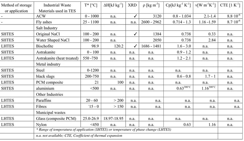
Today, one of the biggest challenges our society must face is the satisfactory supply, dispatchability and management of the energy. Thermal Energy Storage (TES) has been identified as a breakthrough concept in industrial heat recovery applications and development of renewable technologies such as concentrated solar power (CSP) plants or compressed air energy storage (CAES). A wide variety of potential heat storage materials has been identified depending on the implemented TES method: sensible, latent or thermochemical. Although no ideal storage material has been identified, several materials have shown a high potential depending on the mentioned considerations. Despite the amount of studied potential heat storage materials, the determination of new alternatives for next generation technologies is still open. One of the main drawbacks in the development of storage materials is their cost. In this regard, this paper presents the review of waste materials and by-products candidates which use contributes in lowering the total cost of the storage system and the valorization of waste industrial materials have strong environmental and societal benefits such as reducing the landfilled waste amounts, reducing the greenhouse emissions and others. This article reviews different industrial waste materials that have been considered as potential TES materials and have been characterized as such. Asbestos containing wastes, fly ashes, by-products from the salt industry and from the metal industry, wastes from recycling steel process and from copper refining process and dross from the aluminum industry, and municipal wastes (glass and nylon) have been considered. Themophysical properties, characterization and experiences using these candidates are discussed and compared. This review shows that the revalorization of wastes or by-products as TES materials is possible, and that more studies are needed to achieve industrial deployment of the idea.
3 1. Introduction
1.1 Thermal Energy Storage (TES)
One of the most important challenges that current society must face is the satisfactory supply, dispatchability and management of the energy. In this frame, a successful and efficient exploitation of all the energetic resources, fossil and renewable, will be the key factor in order to reach a fair and equitable distribution of the available energy. According to the societal and industrial development previsions, the Energy Information Administration (EIA) predicted an increase of the energetic demand on Organization for Economic Cooperation and Development (OECD) and non-OECD countries of around 25 % and 88 % respectively in 2040 [1]. Predominantly the main responsible of this increase will be the emerging countries where the development of heavy industries such as steel, ceramic, glass, and others has experienced an important growth. In addition, the energy demanded by domestic and transport applications have also suffered a noticeable increase in the last years. The fossil fuel dependence usually suffered by these activities is expected to be reduced in the next decades in favor of alternative renewable technologies.
Among the different renewable energies, thermo-electric power generation in concentrated solar power (CSP) plants presents several strategic advantages when compared with photo-voltaic (PV), wind, geothermal or hydraulic. One of the most representatives is the possibility of heat storage, which allows improving the capacity factor and overall efficiency of the plant [2]. This fact makes large scale solar-thermal electricity generation particularly interesting as it allows adapting the generation to the demand (dispatchability improvement), extending the production to non-solar irradiance periods and equilibrating the power generation avoiding undesirable production peaks [3]. In addition, thermal energy storage (TES) systems are nowadays considered as an integral part of CSP plants, which contributes reducing the electricity costs, increasing of the annual solar-to-electricity efficiency of the plant (13.2 % vs 12.4 % without storage) and providing higher potential viability of the CSP technology [4]. In order to reach the levelized cost of the electricity (LCOE) of 6 c$/kWh predicted by DOE for 2020 [5] and according to the predictions of International Energy Agency (IEA) for the next years [6], shown in Figure 1, the investment costs of CSP plants have to decrease around 50 % from 2010 to 2020. As a consequence, the produced electricity costs would decrease in the same ratio or even faster thanks to a progressive efficiency increase. In the particular case of a 50 MW parabolic trough CSP plant the investment costs of a TES system represents around 10 % of the total plant cost. The investment and performance of TES
4
systems mainly depends on the storage material being in current technologies the most expensive part with around a 50 % of the total TES system [7].
A report published by ESTELA in 2013 [8] highlighted the key issues to be included in the European research programs for the next years, mainly focused on integrated TES systems in CSP plants summarized below:
Reduce the costs of the storage (key performance indicators for 2010: 35,000 €/MWhth, and for
2020 15,000 €/MWhth), and increase the storage efficiency (key performance indicators for 2010:
94 %, and for 2020: 96 %) and dispatchability [9].
Maximize storage capacity of existing designs which reduces the specific storage cost.
Up to now, and due to the variety of TES concepts reflected by different heat transfer fluids (HTF) and operating temperatures, there is not a clear leading technology for next generation of CSP plants and an strong research effort on different alternatives is still needed.
TES systems can also represent a breakthrough concept in industrial heat recovery applications. According to the report of US DOE [10], there are large heat recovery opportunities in different industrial processes. These applications require a particular research and development in order to adapt the heat production to the storage. In this regards, several industrial processes, shown in Table 1, have revealed a strong recovery potential with the subsequent economic and environmental benefits. Estimations [10] show that the implementation of TES systems in industrial heat recovery applications might increase the efficiency of the overall process and decrease the CO2 emissions As it may be seen in Figure 2, CO2
emissions from energy supply (energy generation and transport) and use (final consumption) are the largest source in the EU-28 accounting for 60 % of total greenhouse gas emissions in 2011 [9]. The 4,050 TWh of solar electricity generated by CSP plants in 2050 are expected to avoid around 2.5 Gt of CO2
emissions per year worldwide [11].
In another field of industrial applications [12], TES present high potential. Compressed Air Energy Storage (CAES) is acknowledged as a reliable alternative technology to conventional hydraulic systems. Nevertheless, if the heat of compression is lost, the efficiency is roughly limited under 50 %. Then, the integration of a TES subsystem would allow the valorisation of this heat leading theoretically to an efficiency up to 70 %. This TES unit should operate one to three full charging/discharging cycles per day in the range of 50 to 650 °C using compressed air as heat transfer fluid. Such operating parameters are obviously severe for a sensible heat based TES material. Consequently, only high temperature refractory
5
materials could be considered which are usually too expensive and present too high environmental footprint for such subsystem. Therefore, low - cost and environmentally friendly TES materials are highly needed for the future development of CAES technologies.
1.2 Analysis of the TES materials currently used in commercial applications
A wide variety of potential heat storage materials has been identified depending on the implemented TES method: sensible, latent or thermochemical. The particular application also limits the suitable materials as a function of the operation temperature range, storage capacity, power and other requirements such as low cost. Overall, although no ideal storage material has been identified, several materials have shown a high potential depending on the mentioned considerations.
In sensible heat storage applications, several authors have identified different attractive materials [13,14]. In this scope, according Khare et al. [15] appropriate sensible heat storage requires:
Thermophysical properties: high energy density, heat capacity and conductivity and long term thermal cycling stability.
Chemical properties: chemical stability, non-toxic, non-explosive, low potential reactivity with the HTF and the container material.
Mechanical properties: good mechanical stability, low coefficient of thermal expansion, high fracture toughness and high compressive strength.
Economic properties: cheap and abundant materials with low cost of manufacturing into suitable shapes.
Environmental aspects: low manufacturing energy requirement and CO2 footprint.
Among the large number of materials identified for sensible heat storage applications, two of them present a particular interest: water and different molten salt mixtures. The first one fully meets the necessities of a low temperature storage with a high storage capacity and economic viability. At higher temperatures, the most extended material in sensible heat storage applications are different molten salt mixtures: 60 % wt NaNO3 + 40 % wt KNO3 (the most common solar salt), Hitec (7 % wt NaNO3 + 53 %
wt KNO3 + 40 % wt NaNO2), Hitec XL (12 % wt NaNO3 + 46 % wt KNO3 + 42 % wt Ca(NO2)3), Morton
Solar Salt, etc. Current commercial heat storage applications are mainly based on these materials, which has led to a noticeable maturity level of this sensible storage technology. Anyway, sensible heat storage presents several limitations that next generation storage applications need to overcome. In this frame, the operation temperature range of the salts is limited between 250-265 ºC, which implies an important
6
storage capacity limitation together with the need of continuous heat supply to the salts in order to avoid their freezing. In addition, their low thermal conductivity value, around 0.5 W m-1 K-1, leads to a poor
heat transfer coefficient, which implies the use of complex and expensive heat exchange devices.
The nitrate salts used in CSP are mainly (roughly 60 %) natural products for which Chile is acknowledged to be the worldwide leader for centuries. According to the related literature [16], the peak of production was 3 Mt/year in 1910 and only 0.8 Mt/year in 2007. If the current molten salt TES is applied to the expected CSP market growth [17], 9 to 20 Mt would be needed every year, definitely more than the actual production already shared by the needs in fertilizers and the chemical industry. Alternatively, synthetic nitrate salts could be used as TES materials but this would lead to an increase in the Greenhouse Gas (GHG) content of 52 % [18]. Moreover, the extensive mining of those salts in the Atacama area has led to 132 Mt of wastes and 100 ghost mines over 417 km² of desert. This highlights the fact that even if a material is made of natural resources, its environmental impacts are not obviously negligible.
Latent heat storage method has also identified as a very promising concept in the heat storage frame. Although the number of commercial applications based on phase change materials (PCM) is currently very limited, latent heat storage presents several advantages when compared with sensible, among them, larger storage energy density and constant or quasi-constant operation temperature. Several authors have identified a wide variety of PCM [19-22]. In this case, a high phase transition latent heat, thermal conductivity and density are desirable. Depending on the application, the melting temperature is the other critical aspect. The most interesting potential materials studied by the moment are paraffin, sugar alcohols or salt mixtures. Among the mentioned PCM, the main limitation is a low thermal conductivity value (between 0.5 to 5 W m-1 K-1 [19]). Proposed in the 80´s, metals and metallic alloys have also been
identified as very attracting materials because of their high thermal conductivity value, constant operation temperature and high operation temperature [23-25]. In particular, Mg-Zn and Mg-Zn-Al alloys have revealed a very interesting behavior within the frame of high power and fast thermal response applications but associated with a prohibitive cost.
Thermochemical heat storage has been reported as a very interesting heat storage alternative because of its high potential storage energy density. However, the maturity level of these technologies is still in a preliminary state and a strong research effort is needed in order to become a real and viable alternative.
In order to clarify the level of development of the different storage systems Tamme et al. [26] provided in 2011 the maturity status of TES, pointing out that these technologies with the greatest potential to
7
increase the energy density of the system were also these with less maturity level. As it may be seen in Figure 3, even if their energetic density is quite low compared with other media, sensible heat storage materials are currently the more commercially developed ones. Despite the amount of studied potential heat storage materials, the determination of new alternatives for next generation technologies is still open. In this scenario higher operation temperature levels, up to 800-1000 ºC, larger storage capacities, improved chemical and mechanical stability, optimized environmental footprint and a low cost will be mandatory.
Almost all these mentioned properties related with the heat storage materials have to be well-known before the design and construction of a new TES system. On the other hand, environmental aspects are the less considered ones on the selection of a storage material. In order to evaluate the environmental impact of a given storage system Life Cycle Assessment (LCA) technique was used by Oro et al. [27]. LCA is a technique to assess the environmental aspects and potential impacts associated with a product, process or service. In particular, it takes into the inventory of relevant energy and material inputs and environmental releases to evaluate the potential environmental impacts associated to them. The work presented by Oro et al. analyzed and compared the impact of the manufacturing and operation of three storage technologies based on liquid sensible heat (two tanks with molten salts), solid sensible heat (concrete) and latent heat (molten salts) materials. The analysis shown that the system based on two tanks of molten salts has the higher impact per kWh stored due to the specific equipment to withstand higher temperatures in the facility. On the other hand, even though the energy stored by the system based on concrete was the lowest one, the global impact per kWh stored was also the lowest due to the construction simplicity.
1.3 Low cost industrial waste and by‐product materials
Among the most important improvements needed to overcome current storage limitations are the operation temperature range, storage capacity and total storage cost [8]. An overall enhancement of these issues might lead to an important competitiveness increase of solar-thermal power generation. In short, if the CSP technology wants to be a real alternative to power generation in the next decades, the total LCOE should follow the evolution shown in Figure 4 [5]. According to this prediction, the total cost of the plant should be reduced in 2020 a 51 % and a 42 % in parabolic trough and tower plants respectively, being the cost of the TES system around a 10 % of the total CSP plant [8]. Despite other possibilities of reducing the TES system cost, the cost of the storage material represents an important fraction of the total amount.
8
This makes the search of new low cost storage materials a critical activity in order to reach a cost-effective thermal storage alternative.
In addition, the availability of the storage material in an enough amount is also a key factor to allow the scheduled CSP growth on the next years. Lack in the availability or even a conflict on the final use of the TES material may lead to variability on the price and risks the development of solar power.
In this frame the valorization of industrial waste by-products as heat storage materials has shown a very high potential in order to reduce the cost of the storage [28]. Several waste materials have been considered and analyzed, mainly for sensible heat storage. Among them wastes coming from asbestos (Cofalit®) [29,30], coal fly ashes [31,32], municipal solid waste incinerator (MSWI) fly ash [33], concrete [34] and slag from metallurgic industry [35] has revealed a high suitability for innovative heat storage solutions. This alternative presents several important advantages which might improve the efficiency and cost effectiveness not only of CSP industry but also of the industrial processes producing these by-products themselves. This could help to match the storage cost reduction planned by Tamme [26]. In particular, some waste materials allow high temperature heat storage (up to 1200 ºC), depending on the particular TES concept implemented. This is also an important added value to this type of materials. In the industrial area, the valorization of waste products can also represent a viable alternative to reduce the environmental footprint of factories. In addition, currently, industry has to cover any suitable treatment of the produced wastes, which usually implies an important economic effort in order to inertise, landfill or perform any other procedure necessary to guarantee the satisfactory treatment of the by-products.
Finally, the critical issue in order to obtain an economically viable storage is to reduce the cost of the storage material. Aligned with this statement, one of the aims of this work is the review of low cost heat storage materials. In particular, the valorisation of industrial by-products and waste materials has revealed a high potential in the heat storage frame. In addition, this goal shows a double objective: in one hand, the implementation of improved heat storage devices based on new appropriate materials and on the other hand, the valorisation of waste industrial materials will have strong environmental, economic and societal benefits such as reducing the landfilled waste amounts, reducing the greenhouse emissions and others.
9 2. Industrial waste materials used in TES
2.1 Asbestos Containing Wastes (ACW) 2.1.1 Definition of the waste material
Asbestos has been used worldwide during the XXth century in various well known industrial and domestic
applications, leading to an estimated amount of 174 Mt/year consumption. Obviously, this already high amount of matter is only a fraction of the total inventory of Asbestos Containing Wastes (ACW). In the case of France, 250,000 t of ACW are produced every year, among which only 6000 t are industrially inertised while the rest is stored in landfills waiting for further treatment. Most of the countries have banned its use since 1995 and the asbestos containing materials are submitted to severe rules for dismantling and treatments. The health impacts of those materials are due to the micro fibrous structure of the Asbestos. Therefore, the rather unique industrial treatment approach allowing a full inertisation is necessary based on the melting of the material leading to the irreversible suppression of the fibrous structure.
2.1.2 Treatment technologies
As already mentioned, only melting based processes allow a full inertisation of the ACW. As such a treatment is necessary made at high temperature, around 1400 °C, the process is highly energy consuming and leads to a significant GHG and embodied energy amount of the obtained ceramic. Therefore only high temperature TES applications such as CSP or CAES can really offer advantageous environmental pay back justifying the waste treatment [29].Practically, those melting treatments involve plasma torch or microwave heating sources in semi batch reactors. The ACW are fed under sub-atmospheric atmosphere (avoiding any Asbestos fiber release to the surrounding environment) in the reactor containing a melted pool of matter. Semi batch withdrawal of the matter is poured within cast steel moulds and left for cooling under ambient atmospheric conditions. Then, within those current industrial operating conditions, several structural organization of the material are observed in the ingot [36]. The characterization of those structures have led to the selection of the best one regarding TES applications. Then, specific operating conditions of cooling (active or passive) were defined leading to moulded ceramic modules made of a unique proper structure of fine isotropic micron size crystals. This manufacturing approach was validated at both laboratory and industrial scale. Complementary work was done with success to develop hybrid
10
concentrated solar assisted process allowing significant reduction in the energy consumption of the treatment.
2.1.3 Thermophysical properties, characterization and compatibility studies
Both the glass and the ceramic made from melted ACW were characterized in terms of thermo physical properties of interest for TES applications. Original and valuable characterizations were made on their thermo mechanical properties under thermal cycling and high temperature to assess their ability to sustain thermal stress and fatigue. The obtained basalt-like ceramic presents stable values of its properties in the range of those already known for rocks of similar compositions. Even if the ACW initial composition can be seen as highly fluctuating, the main major involved compounds (O 32 % wt., Ca 31 % wt., Si 23 % wt., Fe-Mg-Al 13 % wt.) control the various properties. As illustrated in the X-Ray Diffraction (XRD) diagram of Figure 5, the glass crystallizes at a temperature of about 900 °C to form a ceramic made of wollastonite, akermanite and augite. As highlighted in the same diagram, the structure of the obtained ceramic is very stable under successive thermal cycling between room temperature and 1000 °C. This result demonstrates the ability of the recycled ACW ceramic to sustain high temperature thermal cycling.
The characterization of the ACW ceramics from room temperature up to 1000 °C led to the following range of values: 3120 kg/m3 in density, 0.800 to 1.034 kJ kg-1 K-1 in thermal capacity, 2.1 to 1.4 W m-1 K -1 in thermal conductivity, 8.8 10-6 K-1 in coefficient of thermal expansion. The behavior of the Young
modulus was studied using an original ultrasonic pulse echography from room temperature up to 1000°C. The results, illustrated in Figure 6, highlight the refractory behavior of those ceramics and then their ability to sustain severe thermal cycling operating conditions. Those assessments were confirmed by extreme thermal cycling made between 500 and 1000 °C under concentrated solar flux with cooling and heating rates of 100, 300 and 2500 °C min-1.
The compatibility of the ACW made ceramics has been studied for various heat transfer fluids (HTF) of interest currently used in TES applications: molten salts, hot air, compressed hot air, oil, hot water and atmospheric steam. The tests were achieved by direct contact between ceramic samples and the HTF under real operating condition range (temperature, pressure, time) for several thousands of hours. Characterizations (scanning electron microscope (SEM), differential scanning calorimetry (DSC), X-Ray diffraction (XRD), etc.) were made regularly in order to follow the possible degradation or modification of the ceramics and eventually of the HTF. Concerning the molten salts, among the various corresponding families, only the nitrates present a good compatibility with the ACW [18,30-39]. Therefore, the recycled
11
ceramic can be used under direct contact with the so-called solar salt NaNO3/KNO3 in thermocline units.
ACW can be also used under direct contact with hot air, up to 1100°C, even under concentrated solar radiation and severe thermal cycling without change [40]. Under compressed hot air, a HTF of particular interest for ACAES and future gas turbine CSP tower systems, ACW presents a structural change from wollastonite to augite leading to an increase of 29 % in its thermal conductivity [12]. Tests with oil, hot water and atmospheric steam were successful even if additional tests are highly needed with pressurized steam.
2.1.4 Storage application modelling analysis
The applicability of those ceramics to large scale TES application was studied numerically in the particular case of the ACAES process [12]. Performances of cumulated charge/discharge cycling on a sub TES unit composed of stacks of flat plates were calculated for various configurations (plate thickness, inter plate distance) and operating conditions. The simulations were achieved under non dimensional approach leading to numerous results highlighting the most relevant ones and the possible potential of improvements. While the basic studied configuration led to possible geometrical configuration in agreement with the expected performances, advanced systems could be developed using more complex geometries (such as static mixers made of stacked corrugated plates) and/or more conductive ceramics. Complementary studies will be achieved following those approaches but specific heat transfer coefficient correlations on complex geometries would be needed.
2.1.5 Lab scale experiences
ACW ceramics were tested in TES lab scale units in the form of granular packing (oil as HTF) and in the form of shaped packing (Figure 7: plates and corrugated plates using hot air as HTF). Hundreds of thermal cycling under operating conditions of ACAES (50 to 650 °C), linear CSP (200 to 400 °C) and central receiver CSP (400 to 800 °C) were achieved. During those experiments, the thermal behavior of both the material and the TES unit were recorded. The TES material was characterized at the end of the experiments for comparison with the initial ceramic. No changes of structure or properties were noticed between raw and cycled modules.
Due to their thermal inertia, conventional TES units can be usually operated under rather limited range of heating/cooling rates. Therefore, in order to assess the limit of use of the ACW ceramics, a high heating rate dynamic solar facility was used [40]. This device is composed of a 2 m ID vertical axis parabola
12
lighted by a two axis heliostat and controlled by graphite blades in between. The upper surface temperature of the sample (in pink in Figure 8) is followed by a pyrometer and controlled by the graphite blades positions. Repeated thermal cycling of heating rates ranging from 100 to 2500 °C min-1 can be
achieved. The temperature at various depths in the sample below the surface is measured by thermocouples. As all possible cracks would lead to an induced thermal resistance, the recorded signal assesses the whole behavior of the material. Moreover, the phase lag and the delay between the curves allow a direct estimation of the thermal diffusivity under thermal cycling at high temperature. Using this device and up to 2500 °C min-1, the ACW samples were able to sustain the fatigue tests between 500 and
1000 °C without failure.
2.2 Fly ashes (FA)
2.2.1 Definition of the waste material
Fly ashes (FA) are micron-size particles present in gaseous effluents produced by industrial combustions (Figure 9(a)) such as coal fired power plants or municipal solid wastes incinerators (MSWI). Those particles are mainly composed of SiO2, Al2O3 and CaO, and can consequently be used as primary
materials for ceramic manufacturing. While coal fired power plant fly ash (CFA) are mainly amorphous, spherical and contain low amount of pollutants, the municipal solid waste fly ash (MSWFA) are rather crystallized, needled shaped and contain critical pollutants such as dioxins (Figure 9(b)).Both are collected from the industrial gas effluents by electrostatic filters and available in the form of light powder similar to regular cement. In some countries less concerned by environmental issues, those FA are even not harvested and induce major health impacts. Most of them are stored in waste disposal leading to land investment and potential pollutant release. Another part is recycled in concrete or in the construction of roads.
2.2.2 Treatment technologies
Municipal solid waste incinerator fly ash (MSWIFA) has been treated by Europlasma/Inertam by plasma torch melting at 1400 °C. At the outlet of the reactor, the molten product is currently quenched and laminated to produce glass plates of about 2 mm in thickness. Those glass plates have been used as primary material for direct characterizations and for subsequent crystallization followed by characterizations. Thanks to the crystal structure, all pollutants such as heavy metals are fixed within the
13
material and no lixiviation effect was detected. Then, the final ceramic can be considered as stable and inert material.
Thermophysical properties of the obtained glass and ceramics were measured, leading to the following range of values (from room temperature up to 1000°C): 2962 to 2896 kg m-3 in density, 0.714 to 1.122 kJ
kg-1 K-1 in thermal capacity, 1.16 to 1.59 W m-1 K-1 in thermal conductivity, 8.7·10-6 K-1 in coefficient of
thermal expansion.The thermal behavior of the obtained glass (dash line) or ceramic (continuous line) from room temperature up to 1100 °C, are illustrated in Figure 10. The glass presents a glass transition at about 650 °C and a crystallization peak at 900 °C while the ceramic is highly stable within the whole temperature range. This illustrates the fact that the glass can be used as TESM in storage systems operated below 600 °C while the ceramic can be used in all temperature range below 1100 °C. The variation of the thermal capacity with temperature of the ceramic is illustrated in Figure 11. This behavior was observed with all recycled ceramics made of melted inorganic wastes such as Asbestos, Fly Ash or metallurgic slag. Even if the compositions of those wastes are different, the main compounds (SiO2, Al2O3, CaO) are
responsible for the observed values of the measured properties within similar ranges.
The CFA have been provided by the EDF Company. Those FA are in the form of spherical particles of few 10 m already known to be more amorphous than MSWIFA and with less pollutant. Those FA have been molten using a lab scale solar parabola (1.5 to 2 kW), the molten product quenched under air and the obtained glass beads crystallized in an electric oven at 1100 °C during 20 h. The obtained ceramic is a Mullite Al6Si2O13, a very valuable and well known refractory ceramic. Nevertheless, the viscosity of the
molten CFA is too high to allow an easy moulding for the production of shaped storage modules. Additional CaCO3 (up to 20 % wt) to the initial CFA before melting led to proper composition for the
modules elaboration. While preliminary experiments were done with synthetic CaCO3, similar work was
achieved with egg shell recycled CaCO3 with success. In both cases, the mullite ceramic is replaced by
the anorthite, another valuable refractory ceramic. According to the fact that egg shells are considered today as highly dangerous wastes from the food industry, this successful mix of CFA and egg shell can be considered as an illustration of the possibility to manage the properties of the final product by use of several wastes. The obtained ceramics have been characterized, from room temperature up to 1000 °C their main properties range are : 2600 kg m-3 in density, 0.735 to 1.300 kJ kg-1 K-1 in thermal capacity, 1.3 to 2.1 in thermal conductivity, 4.0·10-6 K-1 in CTE. Those ceramics can be used as sensible heat TESM up
to 1000 °C.As CFA are in the form of rather regular micron size spherical amorphous silica particles, the treatment can be done by sintering (compression under heat) instead of melting. This approach has been already tested with success by the PROMES CNRS laboratory and the Tellus Ceram Company at lab
14
scale. Up to 100 % CFA containing modules were produced in the form of plates or cylinders and are still under characterizations. This approach could lead to the production of shaped storage modules using less energy than with the melting technique.
2.2.3 Availability/Yearly production & cost
As MSWI are still under extended development in Europe, the corresponding wastes present a wide potential of material of about 1.6 Mt/year (EU 15). As an order of magnitude, a MSWI such as the Calce unit near Perpignan-France produces 6,634 t of FA every year for a treatment of 186,000 tons of municipal wastes. The same unit produces 30 MW of electricity from the combustion heat which could be considered in the energy balance of the FA needed treatment by melting.
As the world production of CFA is estimated to be around 750 M tons per year (42 Mt/year in EU 15), those wastes present a huge potential. Moreover, they are produced by the companies already involved in power production which are those that will also need thermal storage unit in the future. Therefore, those material considered today as environmental and economic constrains can be viewed by those companies as highly valuable primary materials.
In both cases, all FA are produced from MSWI or coal combustion worldwide in huge amounts and then can be considered as particularly strategic in the context of the global energy transition. Moreover, their potential of economical valorization and development of corresponding industrial activity could encourage all countries to harvest those wastes from fumes instead of discharging them to the environment.
2.3 Salt industry 2.3.1 NaCl
A by-product from the potash industry is chosen to test its suitability as TES material [40]. It was identified by X-Ray Diffraction (XRD) as crystalline sodium chloride (NaCl). The original shape of this salt is granulated (Salt A). However, the main drawback of that shape is the air gaps between the grains which decrease its thermal conductivity. For that, different ways to shape and compact the material were considered. In other thermal storage materials, authors propose metal additives, metal fins or graphite to increase it [40], but these solutions represent an increase of the system cost. So, a cheaper option was
15
considered: the addition of water to eliminate air gaps and to achieve a continuous solid form of the salt by evaporating it later. The suitable mixture of salt and water found had an addition of 17 % of water (Salt B).
At the laboratory, thermal conductivity, specific heat capacity and density were measured. Thermal capacity is obtained by multiplying density and specific heat capacity (Cp·ρ). These are the important parameters to determine the suitability of a material to store sensible heat. After the laboratory characterization of these by-products, their properties are listed and compared to other sources (Table 2). It can be seen that NaCl has different properties depending on the source. Moreover, both by-products were tested at higher scale. 59 kg of Salt A and Salt B were thermally cycled from 100 to 200 ºC. The TES tank design were the salts were tested (Figure 12) is based on the concept of a shell-and-tube heat exchanger, consisting of a vertical tube bundle with four tubes through which the HTF is circulated and a housing surrounding the tubes serves as storage material container. Its main characteristics are: 0.05 m3
capacity, dimensions of 0.35 x 0.35 x 0.41 m, and 0.002 m thickness A316 stainless steel walls.
Four experiments varying the length of the charge and the discharge from 4 to 8 h and the heat transfer flow from 1 5o 3 m3 h-1 were performed to calculate: thermal conductivity, thermal diffusivity, energy
delivered and accumulated by the salts and cycle performance. Thermal conductivity and diffusivity results are shown in Figure 13.These analyses show that Salt B (water-shaped) represents a better option as storage material than Salt A due to the reduction of air gaps inside the solid. Moreover, using the data achieved at the laboratory, thermal capacity was calculated and compared with other solid materials found in the literature and similar values to other sensible heat storage materials like concrete and silica firebricks were observed. Thus, NaCl represents an interesting competitor because of its thermal properties, its behavior in a real scale plant and especially because of its price (from 5 to 100 times cheaper than other solid material candidates for sensible heat storage).
2.3.2 Bischofite
Inorganic materials, especially salt hydrates, are the most important group of TES as PCM, and they have been studied for several researchers. This group of materials has attractive properties, as high energy storage density, relatively high thermal conductivity, only slightly toxic, not very corrosive, and compatible with plastics [13,21,42,44-46]. Although salt hydrates are sufficiently inexpensive, non-metallic industry has vast quantities of waste materials or by products, which don’t have or have limited applications. Some researchers have been studied these materials to be applied as TES.
16
In the north of Chile, the presence of the mine industry is tremendously important; one of the main products of non-metallic industry is the potassium chloride. During the production process of this salt in “Salar de Atacama” are obtained several by products and even waste materials, one of this is bischofite, which has as main component MgCl2·6H2O with some impurities. Nowadays bishofite has few
applications, in Europe the main application is for de-icing of roads. In Chile, its uses this salt to compact and improve the mining roads, because of its hydroscopicity. The demand in Chile exceed the 100,000 tons per year, within an approximately price of 40 US$/ton on its low quality variety and the purified bischofite price is closed to the MgCl2·6H2Om but always lower, around 155 US$/tons. Other countries
has also the presence of this salt, in similar processes, this is the case of Israel and The Netherlands [43].
The physical and thermal properties of bischofite were determinate. The chemical analysis showed the main components of bischofite (Table 3) and the mineralization (Table 4) determined that the quantity of MgCl2·6H2O in bischofite is nearly 95 %, moreover according to the mineralization this salts presents the
existence of two hydrated salts, carnallite (KCl·MgCl2·6H2O) and Li2SO4·H2O.
The thermal properties of this salt are near to the synthetic MgCl2·6H2O, with a melting temperature of
Tonset=98.9 ºC and Tonset=114.6 ºC respectively (Figure 14). Also the heat of fusion value is similar 120.2
kJ kg-1 and 126.6 kJ kg-1 respectively; the differences are because of the presence of impurities in
bischofite. Bischofite shows good thermal stability [44], with a mass loss of 0.4 % compare to MgCl2·6H2O which doesn’t present mass loss, within the temperature range from 30 ºC to 140 ºC
measured at aluminium crucibles with lid. Furthermore, about long term cyclic stability, bischofite showed a very good behaviour related to melting point and heat of fusion (see Table 5), but it’s variable in the cooling process: the temperature of crystallization don’t remain constant during the cycles, this is a normal behaviour in hydrated salts, due to most of them present segregation phases or poor nucleation during the solidification process [22, 47].This study also determined physical properties as viscosity, heat capacity, density as a function of temperature and energy storage density (esd), showed in Table 6, demonstrating that bischofite (by-product) present similar properties than synthetic MgCl2·6H2O, even
though with the presence of impurities.
Gutierrez et al. [45] studied the addition of different molecular weight PEG to improve cycling stability of bischofite during heating and cooling cycles, improving the thermal performance of the mixture when applied as phase change material. The results obtained are show in Table 7. According to this research the
17
mixture of bischofite + 5 %PEG 2000, was the most stable due to the crystallization temperature remains within the variation range of 7 °C during the cycles of heating and cooling.
2.3.3 Astrakanite and Kainite
With the aim of testing other wastes usually present in thee non-metallic industry as thermal energy storage materials, the potential of two double hydrated salts were evaluated [46]: synthetic astrakanite (Na2SO4·MgSO4·4H2O) and waste kainite (KCl·MgSO4·3H2O). The samples were characterized by
scanning electron microscopy, SEM-EDX. According to these study astrakanite has crystals separated, with rhombohedra shape, and the presence of impurities was not detected, however, the discarded salt, kainite presents agglomeration. TGA and DSC studies were performed to evaluate the use of the anhydrous phase of astrakanite as a solid TES media at high temperatures. The TGA results showed no weight loss between 320 ºC and 750 ºC. DSC results (Figure 15) revealed that the anhydrous phase of astrakanite presents a reversible melting –solidification behavior in the range from 570 °C to 680 °C, but it is necessary to perform deeply studies.
Heat capacity obtained for astrakanite, kainite and anhydrous phase of astrakanite are show in Table 8. The heat capacity for astrakanite is from 0.9 to 1.2 kJ kg-1·K-1 and for kainite is from 0.8 to 1.0 kJ kg-1K-1,
for the temperature range from 0 °C to 100 °C, and for the anhydrous phase of astrakanite at high-temperature, it is from 1.2 to 2.1 kJ kg-1 K-1.Astrakanite and kainite, waste process-salts from the
non-metallic mining industry in northern Chile, are suitable to be used as heat storage materials at low temperatures, from 0 ºC to 120 ºC. After evaluation of heating and cooling cycles, it was found as well that the anhydrous phase of astrakanite can be used as a solid TES material at a high temperature range, 350 ºC to 530 ºC.
2.4 Metal industry
2.4.1 Definition of the waste material
Steelmaking is one of the worldwide most extended heavy industries with larger development level. Far from reducing the total steel production, in the last 10 years the total produced steel amount has experienced an increase of around 5 % every year [49]. In addition, the steel consumption has also been increased in the same ratio.
18
However, this production activity implies the generation of one of the largest by-product of the high temperature manipulation, extraction and refining of metals: steel slag. This material of the metallurgic industry is generated, essentially, during the melting process of the iron ore and about 10 to 20 % of slag is produced per ton of steel. When the final casting is obtained, the liquid steel slag is easily removed from the liquid steel by density difference and cooled down for solidification. The mentioned process, which is particular of each steelmaker, generates different types of steel slag depending on the furnace technology used, the ore or scrap composition, particular additives introduced in the steelmaking process or the cooling conditions of the slag. In general, slag is a partially vitreous by-product of smelting ore due to separating of the metal fraction from the worthless fraction. It can be mainly considered as a mixture of metal oxides. However, slag can contain metal sulphides and metallic components in the elemental form as well as heavy metal traces, such as chromium, molybdenum or vanadium. Since these substances can be leached to some extent from the slag, possible environmental hazards cannot always be excluded. Moreover, steel-industry slag is alkaline, producing water leachate with a basic pH of approximately 11. Even if slag are from now on officially classified as non-hazardous waste in Europe, dumping slag should not be considered as a long-term solution of waste management and new market should be identified to recycle 100 % of this material.
The European Slag Association [50] classified the slag in different families depending on their nature: Granulated Blast furnace Slag (GBS), Air-cooled Blast furnace Slag (ABS) both coming from the production of iron by thermochemical reduction in a blast furnace, and obtained under different cooling conditions; Basic Oxigen furnace Slag (BOS) formed during the solidification of the steel in a basic oxygen furnace and generated by addition of limestone and/or dolomite; Steelmaking Electric Arc Furnace Slag for Carbon and Stainless steel (EAF C and EAF S respectively) formed during the melting of the scrap in an electric arc furnace; and Steelmaking Slag (SMS) which includes slag from the steel production process to the subsequent treatment of crude steel. Each one of these slag families is identified with the corresponding CAS number.
The main furnaces used in EU27 are Basic Oxygen Furnace (BOF) with 58.2 %, Electric Arc Furnace (EAF) with 41.4 %, and Open Heart Furnace (OHF), with 0.3 % [51].
2.4.2 Treatment technologies
The legal status of the ferrous slag (their classification as either waste, product, or by-product) has been discussed worldwide for more than 25 years. Even though, according to the Waste Framework Directive
19
2008/98/CE – Article 5, steel slag may be currently classified as a by-product because it is produced as an integral part of the production process and its use is certain without any further processing [50].
The effect of the slag on human health and environment was specially investigated during last years. Numerous toxicity and ecotoxicity tests were performed and, on the basis of their results, it could be concluded that slag is not hazardous [50].For this reason additional treatment processes are not needed for ferrous slags. In fact, treatment technologies developed for slags are related with the posterior application of this by-product. In this frame, for an optimal use of ferrous and steel slag the existence of accorded standards, which include the relevant requirements, depending on the field of use, is necessary. Currently, these standards are focused on the use of slags as construction material or aggregate or as fertilizer [50], but most of the European countries have developed their own directives and regulations as a basis for marketing by-products or secondary raw materials. According to these normative the treatment of each slag will vary depending on its slag family. The main general treatments for each slag family are listed in Table 9.
The EU Commission agreed that industrial operations such granulation, pelletisation, foaming, proper solidification connected with a specified heat treatment and separation, crushing sieving (screening) and milling (grinding) are also examples of slag processing [50]. In addition, it was remarked that no negative environmental impact has ever been reported when slag is used in accordance with the requirements of the relevant regulation.
Different treatment methods of steel slag are related to the energetic losses derived from this by-product in the steel industry, around a 6.4 % of the total energy input [52]. The necessity to improve the energetic efficiency of the steel production plants forced the sector to develop new technologies and treatments to recover the wasted heat of the hot slag. These technologies were reviewed by Barati et al. [53] being classified in three categories: recovery as hot air or steam; conversion to chemical energy as fuel or thermoelectric power generation. An innovative treatment technology, which could facilitate the integration of slag in the mentioned valorisation applications and also could open new potential valuable markets for this material, was introduced by Syuhada [54], from the Krakatau Steel Company. This treatment methodology consists on the atomization of liquid EAF S slag directly at the end of the steelmaking process. It permits to obtain spherical glassy pebbles of this material (PreciousSlagBalls®) with a diameter from 0.2 cm to a few cm. This treatment present two important advantages, on one hand it avoids any further moulding or shaping of the solid slag, which represents a high energy demanding process, as it takes the liquid slag directly from the steel production. On the other hand, the flexibility to
20
obtain different diameters of slag balls is an important feature which favors the ulterior use on different applications, from their use as fertilizer to the design and construction of innovative TES solutions based on slag packed bed concepts.
Summarizing, no specific treatment methodology is currently necessary for steel slag. However, the ulterior application of this material could lead to different treatment technologies in order to optimize it for the particular application.
2.4.3 Short overview related with the revalorization of steel slag
Up to now, the revalorization of this material as an added value product represents the main solution to manage this by-product [55-57]. Different researchers have suggested the use of slag for very different applications in several areas depending on the particular composition. In Europe, in 2010 around a 76 % of the total produced slag was revalorized in different fields (Figure 16).
One of the usual applications of slag, due to their high durability and strength, is road construction [56-58]. Their high bulk density and abrasion together with the rough texture make slag a very suitable material for construction purposes. Slag also presents a high binder adhesion and frictional or abrasive resistance, making possible their use as aggregates in surface layers of pavement and asphaltic layers. The second most extended application of this material is the cement and concrete production [59-65]: its addition as arid aggregate represents one of the biggest current alternative to the reutilization of slag.
The use of slag as potential material for ceramic glass production has also been proposed in references [66,67]. On the other hand, based on the porous structure of steel slag, Shi et al. [68] and separately Chamteut et al. [69] have extensively studied the possibility of their use in waste water treatment. In this frame, several contamination types have been successfully eliminated, for example by mercury or arsenic adsorption. Some authors [67, 68] also suggest the CO2 capture and flue gas desulfurization by using slag.
Finally, the use of the slag in agriculture as fertilizer is another extended application due to the high mineral content of slag, mainly CaO, SiO2 and MgO [50].
The European Slag Association reported a complete and wide range of application fields for the different types of slag (Table 10).
21 2.4.4 Availability, production and cost
Steel slags represent, in mass, between 15 to 20 % of the total production of the steelmaking process [71]. According to Elliot et al. [49] in 2014, around 1500 million tons of steel were produced. The total produced steel slag at global scale was close to 250 million ton. As a consequence, the appropriate treatment of this by-product is a challenging issue, which has to be solved successfully. In Europe, where around 16 % of the worldwide steel production is carried out [52], about 76 % of slag is re-used in different applications. The remaining 24 % is landfilled (13 %) and stored in the steelmaking plant (11 %).
Recent data published by U.S. Geological Survey, Mineral Commodity Summaries estimated the price of slag increased from $17.6 per ton in 2005 to $23.0 per ton in 2009 [72] quite cheaper than the common storage materials used until the moment as molten salts.
2.4.5 Revalorization of steel slag as TES material: strengths and weaknesses
International Energy Agency (IEA) established thermal, chemical, mechanical and economic requirements for TES materials, among others inexpensive, available in large quantity without conflict of use, stable up to 1000 °C, compatible with heat transfer fluids and non-toxic.
Thermophysical properties of ferrous slag, detailed later, indicate very appropriate values for the use of this material in TES applications according the IEA criterions. In addition, slag shows an extended thermal stability range, up to 1200 ºC, limited by the melting process of this material. This allows a high operation temperature, suitable for a wide range of heat storage applications, from thermo-solar power generation to industrial heat recovery. On both applications, the potential implementation of a ferrous slag based packed-bed storage solution could be successful. On one hand, on the CSP frame, the substitution of large amounts of molten salt by this low-cost by-product in a single storage tank could lead to a substantial cost reduction of the storage system, and hence, of the produced electricity. This concept is not only valid for current storage technologies based on molten salt up to 565 ºC, it can also be suitable for next generation power plants where the operation temperature will be higher, up to 800-1000 ºC. In addition, slag does not need any further treatment in order to be used as heat storage material, and can be directly obtained and conformed from the EAF [55,74].
22
On the other hand, the main drawback using slag as TES material may be the compatibility between the by-product and the HTF or the container material. Positive results may permit a direct contact between the slag and the fluid, which the subsequent elimination of sophisticated heat exchangers.
Overall, TES systems based on slag as thermal storage material represents a low-cost breakthrough solution both to the CSP heat storage and to the industrial waste heat recovery.
2.4.6 Thermophysical properties, characterization and compatibility studies
A complete characterization of slags is necessary to evaluate their suitability to be used as TES material. Different authors analyzed the composition and thermophysical properties of this by-product showing very promising results that would make it suitable to be used in TES applications.
Mineralogical characterizations of different slag types were presented by de Brito et al [74] revealing the major and minor substances found in each slag type with the corresponding crystallographic structures, although no data about the composition was provided (Table 11).
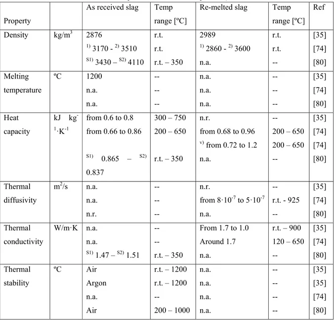
Calvet et al. [30,36] presented an experimental characterization of as received and re-melted EAF S slag (as received slag melted and solidified again to obtain a desired shape) coming from steel production process. In these publications the TGA results shown no mass loss between 300 °C and 1200 °C under Argon, and a small mass gain when dry air is used as purge gas due to the oxidation of metal iron (3.15 %) still contained in the waste.
The heat capacity of black slag samples was measured in the 200-750 °C temperature range and showed values between 0.600 and 0.800 kJ kg-1 K-1, as shown in Figure 17. Thermal conductivity was measured
with the laser flash method and is decreasing with temperature from 1.7 W m-1 K-1 at 50 °C to 1 W m-1 K-1
at 900 °C (Figure 18). This relatively small value imposes to increase the heat exchange surface between the HTF and the TES material to obtain satisfactory heat transfer in the future storage system.
Figure 19 reports the composition of the slag, which was measured together with the density, melting point, thermal stability, heat capacity and thermal conductivity.
Thermophysical properties were also reported by Gil et al. [75]. In this publication the skeletal and bulk density for both re-melted and as received slag was measured. The authors completed the characterization
23
of Calvet including values of density, heat capacity, thermal diffusivity and thermal conductivity of re-melted slag.
Ortega et al. [81] compared the thermophysical properties of two EAF slag coming from different steelmaking companies (named Slag1 and Slag2). The main difference between the materials was the cooling conditions applied after the steelmaking process: one of them was cooled down rapidly, 3-4 hours, by using water while the second one was cooled down in open air during 2-3 days.
Thermal stability experiments were conducted by thermogravimetric analysis in the range of 200-1000 ºC and chemical stability was studied using a chamber furnace at 1000 ºC and testing the samples during 500 hours under air atmosphere. The results shown both slag are thermally stable at least up to 1000 ºC and any chemical reaction was detected. The authors also measured the slag density at room temperature and their heat capacity and thermal conductivity at 350 ºC concluding that the results revealed slag as suitable candidate to be used as TES material.
The results [36,75] are summarized in Table 12were slight differences in the thermophysical values are observed. This might be related to the heterogeneous nature of this material. Overall, the authors concluded that according to the results obtained, both slag can be considered as potential TES material candidates.
A chemical compatibility analysis has also been reported by Mills [81] who presented a study of the slags reactivity with the container, the metal and the atmosphere. These studies, mainly focused on the reactivity of the slag with the typical elements used during the production of the steel, may be considered a first approach on the knowledge of compatibility of this by-product with other materials.
The reaction between the slag and the container is only described and few recommendations about the alloying metals to be used in the container are presented. Slag and metal reactions were softly studied in order to determine unwanted reactions in continuous casting. Regarding to the atmosphere, Mills analyzed the formation of different oxides depending on the oxygen, nitrogen and moisture concentrations.
A more complete compatibility study by Ortega et al. [82] presented results of slags in contact with three different HTF: synthetic oil (Syltherm 800), molten salts (Solar Salt) and air. The target was to analyze
24
the level of reaction of two different slag with these fluids in real working conditions (CSP plants) at 400 ºC, 500 ºC and 1000 ºC respectively.
The experiments were performed putting in contact a sample of slag with the correspondent fluid in a sealed crucible with controlled atmosphere during 500 hours. After this period the samples were analyzed by XRD measurements and under scanning electron microscopy and thermochemically characterized. The results revealed that some structural modifications in the slag occur when working with air at 1000 ºC as HTF. These modifications were also observed in previous works by the same author [80] who concluded after these transformations, which occurs during the first hours/cycles, the material obtained is totally stable. Regarding the Solar Salt and Syltherm 800 results, no mayor transformations have been observed neither un the fluids nor in the slags, concluding that the slag are fully compatible with both HTF at the tested temperatures.
2.4.7 Storage application modelling analysis
The thermophysical properties revealed by the slag make this material very attracting for several TES applications. However, as usual with novel TES materials, prior to the construction of any storage device based on steel slag, a strong modelling and design effort is still needed. In this sense, three different simulation areas are of special interest: modelling of the thermophysical properties of slag, basic design and modelling of heat storage concepts and devices, and thermomechanical modelling of the storage.
On the first step, the modelling of the thermophysical properties of steel slag, Mills [82] and references therein has developed different models and calculations in order to predict the most relevant thermophysical properties of the slag. In particular, numerical fits, neural networks, structural, thermodynamic and molecular dynamics models were used and developed. These techniques permitted to obtain an accurate description of the liquids and solids temperatures, heat capacity, enthalpy, thermal expansion, density, viscosities, electrical conductivity, surface tension and thermal conductivity.
Regarding the second modelling stage, basic design of heat storage devices, very limited information can be found in the literature related to steel slag based TES concepts. In this frame, CIC Energigune has identified the solid packed-bed arrangement of EAF slag pebbles as the most promising concept to use this material in heat storage applications [81, 83]. Packed bed storage is a well-known and mature technology implemented in diverse TES applications [83-85]. From this starting point, several storage solid materials and heat transfer fluids (molten salts, thermal oil and air) have been modelled as potential
25
TES device candidates in a thermocline-type storage [4,88]. Moreover, the underlying basis of packed bed modelling is also well developed and validated in different works.
For the particular case of EAF slag in packed bed arrangement, Ortega et al. [83] have performed Computational Fluid Dynamic (CFD) simulations establishing the optimization of the operation mode of the storage unit as a function of the inlet/outlet temperature tolerance of the system, oriented to potential new generation CSP plants. In their calculations they also estimate the overall efficiency of the storage system, determined between 58-93 % depending on the transient or stationary operation of the system. The optimization of the slag pebble diameter and its impact on the overall behavior was also analyzed. As a conclusion, the authors obtained very promising results, which guarantee the viability of EAF slag as storage material in packed bed arrangement.
2.4.8 Lab scale experiences
The slag have been moulded in form of plates (Figure 20(a)) and corrugated plates (Figure 20(b)) by PROMES CNRS Laboratory to be assembled (Figure 20(c)) and use in a small scale TES system using air as heat transfer fluid in direct contact with the storage material by [36]. Tests consisted on 25 cycles of 6 hours each one, with temperature variation from 100 ºC to 700 ºC and the results shown the re-melted slag was stable after more than 25 thermal cycles.
This test has validated the approach of using slag as TES material at laboratory scale. More complex geometries such as corrugated plates will be tested for comparison on their performances related to thermal storage.
2.5 Other metal industries
2.5.1 Waste from recycling steel process
Barreneche et al. developed in 2012 an elastomeric matrix made with EPDM filled with Electrical arc furnace dust (EAFD) and PCM [89-91]. Their composition is listed in Table 13.The PCM used to manufacture the new materials was RT-21 commercialized by Rubitherm. This PCM has 21 °C as melting point and its phase change enthalpy is 100 kJ kg-1.
26
On the other hand, EAFD is a brown powder containing heavy metals and it is classified as hazardous waste in most of the industrialized countries, requiring a treatment previous its landfill. For this reason, the process of incorporating EAFD as a filler into a polymer matrix, in order to obtain a composite formulation that can yield a mouldable heavyweight sheet useful for increase acoustic insulation in constructive systems is a feasible method to valorize this waste and to achieve one way to encapsulate/stabilize PCM.
Furthermore, the obtained results were compared with the results obtained for a commercial material characterized following the same assays and experiments. Thus, the advantages and inconveniencies presented for EPDM matrix may be shown and compared with the other two materials studied (TEXSOUND and EVA/EXACT).
Tensile strength test was done at room temperature conditions (around 20 °C) and the results of the mechanical properties average are listed in Table 14 as well as the thermophysical characterization and thermal conductivity values obtained.
The thermal performance of this dense sheet has been already tested in start-stage in an experimental set-up located in Puigverd de Lleida (Figure 21). The material has been added in order to increase the thermal inertia of internal walls. The two cubicles were provided with an internal wall in order to simulate two different environments. Each area is equipped with a heat pump which located in the environment far from the dense sheet was programmed to operate between two different set points of 28 ºC and 18 ºC in cycles of 12 hours. The thermal response of the environment close to the dense sheet is evaluated.
2.5.2 Waste from copper refinement process
By-products coming from the copper industry (BPC) are promising materials to be used as STES material [93,94]. Navarro et al. have evaluated the BPC stabilized in Portland cement properties as sensible heat TES by using design of experiments (DOE). The energy density (ren) of these formulations, calculated by thermophysical characterization and bulk density, follows the Eq. 1 where BPC is the percentage in weight of the waste and percentage in weight of water is H2O.
27
Therefore, the energy density of the final compound is increased by increasing variables (BPC content and water ratio). However, the mixing process is more difficult when BPC percentage is higher than 77 % wt difficult. Moreover, the thermal conductivity of the samples under study does not depend on the BPC content and it is accounted around 1 W m-1 K-1. The optimum formulations to be used in TES applications
were those with a composition close to BPC content of 77 % and a water ratio of 0.57 %.
On the other hand, some slag from Cooper as well as from steel recycling process were evaluated and compared by Navarro et al. in 2012. The properties of these wastes were introduced in a material selection software and the evaluation of the selection were published [94]. This study demonstrated that several wastes (WDF, IB, Cofalite and WRutF) are cost effective materials to be used as sensible heat TES for an application such as concentrated solar plants, solar cooling, etc.
2.5.3 Dross from the aluminum industry
Aluminum industry is producing as well some waste called dross. Generally, in the aluminum process, dross represents more than 4 % of the total primary aluminum production and 20 % of the secondary aluminum production. In 2013 the yearly world production of primary and secondary aluminum raises up to 70 million metric tons despite the global economic crisis. This production generates between 1.5 and 2.5 million tons of dross that were landfilled.
In the United Arab Emirates (UAE), each year Emirates Global Aluminum (EGA) is producing around 2.3 Million tons of aluminum, generating large amount of Al dross. These wastes are for now stored on site as landfilling is totally forbidden in the UAE. Finding new solutions of waste management become then crucial. Al Naimi et al. [95,101] have studied the composition and thermal stability of as-received Al dross samples provide by the EGA Company. The selected samples in this work were aluminum white dross (AWD) (see Figure 22 (a)) and aluminum pot skimming (APS) (see Figure 22(b)) from primary aluminum process.
In aluminum production, the process of reduction of alumina (Al2O3) consumes the carbon anodes which
creates a layer of carbon dust plus some bath contents such as alumina (Al2O3) and cryolite (Na3AlF6)
floating at the surface of the molten bath. This layer which is skimmed beforehand tapping the molten metal is the APS.
28
AWD is generated in casting operations and floats at the surface of the molten aluminum. Table 15 is presenting the chemical elements of the 2 samples measured with an X-Ray fluorescence (XRF), Niton XL3 XRF from Thermo scientific. Due to the limitation of the instrument, light elements (with atomic number (Z=16) and lower) could not be detected. The mass fraction of the light elements is contained in Bal* in the table. More than 80% of APS is contained in Bal* which was expected as APS is composed mainly of carbon as previously detected by EDS in the same work. Around 28% of aluminum is still contained in AWD. This is the reason to reprocess it in secondary aluminum production. The 67 % in Balance in the table can be explaining by the Oxygen not detected by the XRF tool previously detected with EDS.
The thermal stability of the 2 samples were studied with a simultaneous thermal analyser (STA) 449 F3 Jupiter from Netzsch Company. Figure 23shows the mass of the samples (in percent) versus time during thermal cycles from room temperature to 1100 °C. The APS sample starts to decompose around 500 °C and is then not suitable for higher temperature applications. On the other hand the mass of the AWD is increasing of around 10 % and is stabilized after the first cycle. This is due to the oxidation of the large amount of aluminum still contained in the material (27 %). Generally this AWD is reprocessed to extract as much as aluminum metal as possible from it. This step generates a new waste called aluminum black dross (ABD) which is currently under study at the Masdar Institute and is a new promising candidate for TES applications.
2.6 Other industries
Three wastes and thirteen by-products from different industrial sectors (H3PO4 production process,
biodiesel production, biomass pyrolysis and fiber production) were analyzed in [96,97]. In order to analyze the suitability of these materials as latent TES materials, measurements have been accomplished with DSC Netzsch F3 Maia. Sample mode without correction or baseline, heating rate between 0.5 and 2 K min-1 and sample mass around 20 mg was used to obtain first results in enthalpy –temperature curves.
Once the measurements were performed, four candidates were found. In Table 16, the source, the phase change and the potential of these candidates is shown.
![Table 1 Potential wastes heat amount and temperature of different industrial processes [10]](https://thumb-eu.123doks.com/thumbv2/123dokorg/4426874.29302/41.892.244.650.794.1077/table-potential-wastes-heat-temperature-different-industrial-processes.webp)
![Table 4 Mineralization resulting of a bischofite sample [43]. 2 Compound [%] NaCl 0.90 KCl 0.20 MgCl 2 ·6H 2 O 94.80 KCl·MgCl 2 ·6H 2 O 1.80 Li2SO 4 ·H 2 O 3.20 3](https://thumb-eu.123doks.com/thumbv2/123dokorg/4426874.29302/42.892.167.707.469.695/table-mineralization-resulting-bischofite-sample-compound-nacl-mgcl.webp)

![Table 11 Mineralogical composition of different slags [73]. 1](https://thumb-eu.123doks.com/thumbv2/123dokorg/4426874.29302/45.892.82.776.181.1062/table-mineralogical-composition-different-slags.webp)
![Table 14 Mechanical and thermal properties of dense sheet materials under study [88,89]](https://thumb-eu.123doks.com/thumbv2/123dokorg/4426874.29302/47.892.102.764.186.413/table-mechanical-thermal-properties-dense-sheet-materials-study.webp)