IOP Conference Series: Materials Science and Engineering
PAPER • OPEN ACCESS
An engineering study of a Bronze Age war chariot
To cite this article: A Mazzù et al 2018 IOP Conf. Ser.: Mater. Sci. Eng. 364 012016
View the article online for updates and enhancements.
Related content
Structural integrity of wind turbines impacted by tropical cyclones: A case study from China
Xiao Chen, Chuanfeng Li and Jing Tang
-Apparatus for Electrical Measurement of the Resistive Force on a Wheel Rolling on Soft and Uneven Grounds
Kiyoshi Takahashi, Shigeaki Yokoyama, Hisashi Ohta et al.
-A modern Fizeau experiment for education and outreach purposes
O Morizot, A Sellé, S Ferri et al.
1234567890‘’“”
Florence Heri-Tech – The Future of Heritage Science and Technologies IOP Publishing
IOP Conf. Series: Materials Science and Engineering 364 (2018) 012016 doi:10.1088/1757-899X/364/1/012016
An engineering study of a Bronze Age war chariot
A Mazzù1,3, F M Gambari2, S Uberti1, I Bodini1, S Pasinetti1 and G Sansoni1 1 University of Brescia, Department of Mechanical and Industrial Engineering, via Branze, 38, 20123 Brescia (Italy)
2 Museum of Civilisation, P.za Guglielmo Marconi, 14 – 00144 Rome EUR 3 Corresponding author: [email protected]
Abstract. The Bronze Age crossbar wheel found in the XIX century in Mercurago (Italy) is an amazing example of the technical innovations stimulated by the diffusion of horse draught war chariots in Europe across the third and second millennium b.C. In this paper the tools of modern engineering were used to study the structural issues concerning the wheel and the chariot it should be attached to. In particular, the laser-scanner technology and finite element analysis were used for investigating the dimensional, shape and assembly issues of the wheel, as well as for assessing its structural integrity under operating conditions. The role of the inserted nave, which could be similar to modern bushings, was particularly emphasised, as it is a very innovative solution for that time. The performance of a war chariot equipped by this wheel was studied by means of a vehicle dynamics simulation software, hypothesizing two different chariot structures on the basis of Armenian and Egyptian evidences respectively. The former is probably more similar to the chariot to whom the Mercurago wheel was attached; the latter is technically much more advanced. The results of the analysis allowed obtaining important information about the chariot stability, reliability and structural integrity.
1. Introduction
The invention of the wheel was a key factor in the development of prehistoric cultures in the Old World. The archeological evidences suggest that important social, economic and technological changes occurred across the fourth and the third millennium B.C., providing the preconditions for the development of the earliest wheeled vehicles [1]. In particular, cereal cultivation and animal domestication spread out all over the continent, stimulating the employment of the ox as draught animal. The availability of this animal allowed the development of sledges and wheeled vehicles for transport. The earliest wheels were massive wooden single pieces, with integral nave, obtained from planks cut from tree trunks through wedges. A natural evolution of this technology was the development of tripartite wheels, obtained by assembling three planks cut out from a narrower log. The three parts of the wheel could be assembled by internal dowels and/or external battens. In some cases, the wheels were turning around the fixed axles, and could have integral or inserted nave. In other cases the wheels were fixed to the turning axle through square mortises. The evidences of vehicles equipped with these wheels are usually four wheeled wagons and, more rarely, two wheeled carts, suitable for heavy and slow transport by means of couples of yoked oxen.
The scenario of the wheeled vehicles changed by the end of the third millennium B.C. with the diffusion of domesticated horses throughout Europe. The new motive force provided by this animal allowed dramatically increase the ground transport speed, stimulating the development of lighter and faster vehicles. The new invention was the chariot, a light, resistant two-wheeled vehicle, aimed at
2
1234567890‘’“”
Florence Heri-Tech – The Future of Heritage Science and Technologies IOP Publishing
IOP Conf. Series: Materials Science and Engineering 364 (2018) 012016 doi:10.1088/1757-899X/364/1/012016
rapidly displacing one or two persons. This innovation likely started from the Near East, mainly for war and ceremonial purposes, subsequently spreading all over Egypt and Europe and becoming a key device up to the ancient empires [2,3]. In particular, the six complete chariots found in 1922 in the tomb of the Egyptian Pharaoh Tutankhamun, and two other similar ones (the “Florence chariot” and the “Yuia-Tuiu” chariot) attracted the attention of scientists of ancient technologies, because of their high efficiency and the surprising level of technological knowledge required for realizing them [4,5]. The chariots of Near East and Egypt communities in the second millennium B.C. had spoked wheels, particularly efficient in terms of strength/weight ratio.
At an intermediate technological level between the earlier bulky wheels and the advanced spoked ones stands the crossbar wheel, whose a well-known evidence is the one found in the XIX century in Mercurago, in northern Italy. Nowadays, a plaster clast of this wheel remains, conserved in the Antiquity Museum of Turin (Italy), as the technologies available at the time of the finding did not allow the conservation of wooden evidences. This wheel, dated between the XVIII and the XIII century B.C., is characterized by a diametric bar, thick enough in the central region to accommodate an inserted nave, with four thinner rods departing eccentrically on each side of the nave, and terminating with their ends mortised into the felloe. The overall shape and assembly of this wheel, as well as the constructive complexity and optimized structure, makes the hypothesis that it was destined to a war chariot the most probable.
In this paper, the results of a technical study conducted on this evidence are presented. In particular, laser-scanner technology and finite element structural analyses were used for investigating some open questions about the wheel structural and functional concept, the assembly techniques and the materials. Subsequently, preliminary analyses of the performances of a chariot supported by this wheel were conducted by means of a vehicle dynamics simulation software, considering two chariot configurations based on Armenian and Egyptian evidences.
2. Analysis of the wheel of Mercurago
The original plaster clast of the wheel of Mercurago was analysed by means of optical laser scanner acquisition, aimed at evaluating and measuring its overall geometry and particulars. Subsequently, a solid virtual model of the wheel, as it should be when it was in use, was built and analysed by finite element simulations, in order to investigate constructive and structural issues. The details of such analysis are published in [6]; here the main data about the methodology and results are summarized. 2.1. Laser scanner acquisition of the original plaster clast
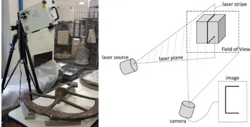
Optical acquisition of the wheel surfaces was carried out by the system illustrated in Figure 1. It consists of a laser beam, expanded by a cylindrical lens, scanning the whole object; a video camera for the deformed laser beam acquisition; a software for the elaboration of the acquired point cloud.
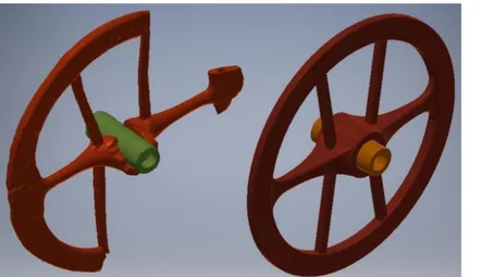
Figure 2 shows the 3D model of the wheel, with the nave virtually inserted. The crossbar thickness increases as far as approaching the wheel center, therefore optimizing its resistance to the bending moment due to a lateral force. The crossbar ends are spade shaped, in effects integrating the rim structure. The ends of the felloes are connected to the crossbar ends by internal dowels, whose slots are visible in the free crossbar end. The rods end with a tapered wedge shape; signs of somewhat like putty or glue are visible at the entrance of the mortice: this reveals the willing of realizing a very tight joint. The rest of a broken rod is even visible: in the mid of the cave a prominence of circular section with two wings on the sides appears: maybe it was a metallic insert, aimed at enforcing the joint. Other relevant information can be obtained by the observation of the coupling between the nave and the wheel hub. The features of the coupled surfaces were quantitatively examined on the virtual model. The external radius of the nave was is about 48–49 mm in the central zone; the internal radius of the wheel hub is larger near the ends, but it lowers down to less than 49 mm in the central region. These measurements show that the two members should be coupled by interference, even necessary to prevent axial pulling out of the wheel. Even some longitudinal grooves on both of the coupled surfaces, shown in Figure 3 seem to confirm this hypothesis, as they could be the marks of the nave insertion and extraction.
1234567890‘’“”
Florence Heri-Tech – The Future of Heritage Science and Technologies IOP Publishing
IOP Conf. Series: Materials Science and Engineering 364 (2018) 012016 doi:10.1088/1757-899X/364/1/012016
Figure 1. Optical acquisition set-up
Figure 2. Virtual 3D model of the Mercurago wheel, with particulars
Figure 3. Longitudinal
marks on the hub and the nave, likely due to insertion with
4
1234567890‘’“”
Florence Heri-Tech – The Future of Heritage Science and Technologies IOP Publishing
IOP Conf. Series: Materials Science and Engineering 364 (2018) 012016 doi:10.1088/1757-899X/364/1/012016
2.2. Finite element analysis
Several finite elements analyses were carried out with the ABAQUS 6.14 software in order to investigate the structural issues. Figure 4 shows the solid model of the integral wheel reconstructed from the digitalized model by means of the SolidWorks 2013 CAD software. The internal surface of the hub is tapered; the external diameter of the nave was set so that an interference ranging from 1 to 2 mm in the central zone was established.
It is thought that both the felloes and the crossbar were in some hardwood, as they were called to give structural solidity to the wheel and to resist penetration by external bodies in the contact with soil. The same hypothesis can be assumed for the dowels, given their crucial role in the wheel structural integrity. Verisimilarly, a particular walnut species, nowadays extinct, could be employed. More uncertain is the material used for the nave and the rods: the implications of using a softwood or a hardwood were investigated. Nowadays, it's impossible to exactly know the mechanical properties of the materials employed for the wheel construction; furthermore, the wood properties are highly changing depending on the wood age, treatment, atmospheric conditions, etc. In the present paper an estimation was done on the basis of the properties of some woods presently in use, but it has to be taken as an approximation able to give a trend about the wheel behaviour. In this paper, the possible properties of a hardwood and a softwood were approximated with the average properties of the black walnut and the northern white cedar respectively, with 12% moisture content, according to the data published in [7]. Two loading conditions were set, hypothesizing two occupants on the chariot: one wheel bumping on a soil asperity at 40 km/h in rectilinear run, and running a curve of 5 m radius at 20 km/h. Figure 5 shows the wheel deformation in curve, amplified by a factor of 5. Other analyses considering a leather tyre wrapping the felloes were carried out, in order to investigate the effect of such technical device which was proven to be in use in the antiquity [1].
Figure 4. From the acquired 3D model to the reconstructed full
wheel model.
Figure 5. Deformed wheel in curve
(amplified 5 times). The main findings of the finite element analyses were the following:
The wheel structure was very efficient in terms of stiffness/weight ratio (its weight was only 7-8 kg) when loaded in radial direction (i.e. in straight running). In curve, the lower stiffness of the rods with respect to the crossbar was a weak point: these had to be realised in hardwood for supporting the lateral forces, but this could not be enough in the simulated tight cornering. The leather tires had the effect of significantly reduce the stresses on the felloes, therefore it is
very probable that these were used.
The inserted nave had probably a more functional rather than structural role: if made in softwood, being subjected to higher wear, it could more easily adapt itself to the rolling coupling
1234567890‘’“”
Florence Heri-Tech – The Future of Heritage Science and Technologies IOP Publishing
IOP Conf. Series: Materials Science and Engineering 364 (2018) 012016 doi:10.1088/1757-899X/364/1/012016
with the axle, preventing the risk of wheel blocking; furthermore, it would prevent wear of the axle. At the end of the battle it could be easily replaced by a new one. All these considerations allow supposing that it was a sort of spare part, with a role similar to that of the modern bushings. This would be a very innovative technology for that time, unfound even in more advanced chariots such as the Tutankhamun class ones.
3. Dynamical analysis of the chariot
A dynamical analysis of the behavior of a war chariot equipped with the Mercurago wheel was carried out with the aim of verifying the performance in battle. As the original chariot is not known, two configurations, based on archaeological evidences, were analyzed, in order to compare different design solutions.
The first solution is based on the Tutankhamun chariots [3-5], which are the most advanced ancient devices: these are made by very complex components, whose construction required highly specialized workforce. For the aim of the present study, its main feature is that the axle was beyond the occupants: this way, the elasticity of the pole, coupled with the damping of the floor which was made by a texture of leather stripes, should provide a very good stability. Furthermore, longitudinal oscillations, due to the horses gallop, were damped by the connection between the pole and the axle.
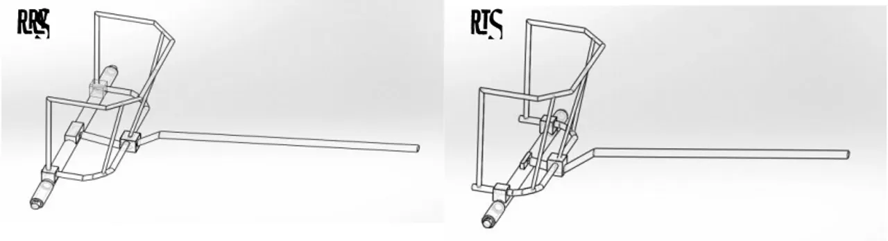
The second solution is based on the evidence of the Armenian chariots found in Lchashen [1]: in this chariot the occupants stood above the axle, and the damping effect relied on the floor. No longitudinal oscillation damping was present as well. This solution, much simpler than the former, was likely more similar to the chariot to whom the Mercurago wheel was attached, being more suitable for small societies as the northern Italian ones were. For the aim of this paper, this solution differs from the previous for the position of the axle. The schemes of the two chariots are shown in Figure 6.
a
b
Figure 6. Schemes of the analysed chariots: a) Egyptian; b) Armenian
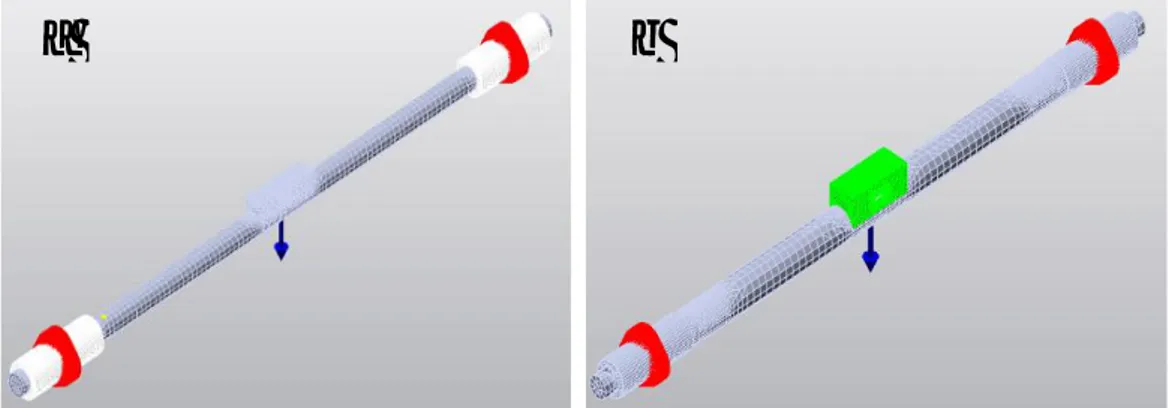
All joints between the axle, the pole and the cockpit are realized by deformable cubes, aimed at simulating the behavior of bindings realized by leather laces. The axle end diameter is known through the internal diameter of the nave (60 mm); however, it is not known whether such diameter was constant along the whole axle, or if it was reduced at the ends for housing the wheels and blocking them axially. For each chariot, therefore, two different solutions were tested (see Figure 7): the first one with a constant diameter, equal to the internal diameter of the nave, along the whole axle length; the second one, with the diameter equal to the external diameter of the nave (100 mm) in the central zone, reduced to 60 mm at both of the ends at the coupling with the naves.
The dynamical analysis was performed by the CARSIM software, normally used for simulations of vehicle dynamics, which requires a schematization of the vehicle as an assembly of rigid bodies connected by springs and dampers (concentrated parameters model). Therefore, the elastic parameters of the two vehicles had to be preliminary determined by means of finite element analyses: they were subjected to vertical, longitudinal, lateral and torsional loads, and the corresponding displacements were measured in order to determine the equivalent spring constants by the load/displacement ratio. The materials considered were a stiffer wood for the axle (longitudinal modulus of elasticity EL = 14190
6
1234567890‘’“”
Florence Heri-Tech – The Future of Heritage Science and Technologies IOP Publishing
IOP Conf. Series: Materials Science and Engineering 364 (2018) 012016 doi:10.1088/1757-899X/364/1/012016
N/mm2) and a slightly less stiff wood for the framework and the pole (E
L = 12320 N/mm2). Both
materials were considered orthotropic elastic, but as all component are subjected mainly to bending stresses, the influence of the elasticity constants in the other directions is negligible. Again, these material elasticity constants have to be taken as indicative.
a
b
Figure 7. Schemes of the analysed axles: a) thin axle; b) reinforced axle
M
pk
p, cpM
ck
a, caM
wM
wk
l, clM
pM
cM
wM
wa
b
k
a, caFigure 8. Concentrated parameters schemes of the simulated chariots: a) Egyptian; b) Armenian.
Figure 8a shows the schematization of the Egyptian chariot. In this scheme, the transported mass Mp
is connected to the chariot by a spring of constant kp and a damper of constant cp, which represents the
vertical elasticity and damping of the framework and the pole. The chariot mass Mc is connected to the
wheels by means of two spring/damper couples of constant ka and ca respectively, which represent the
properties of the two half-axles. Furthermore, a longitudinal spring/damper couple of constants kl and cl
connects the whole draught mass to the horses: such constants are given by the properties of the chariot frame and the pole in longitudinal direction, as well as by the pole-axle joint. The wheels, of mass Mw,
should be connected to the soil by means of a springs/damper couple representing their own properties; however, these effects were considered negligible with respect to the action of the other components.
1234567890‘’“”
Florence Heri-Tech – The Future of Heritage Science and Technologies IOP Publishing
IOP Conf. Series: Materials Science and Engineering 364 (2018) 012016 doi:10.1088/1757-899X/364/1/012016
Figure 8b shows the scheme of the Armenian chariot. There is not a suspension system between the chariot and the transported mass because this stands directly on the axle. The system for longitudinal oscillation damping is absent as well. The values of the masses, spring constants and damping coefficients for the two chariots in both of the axle diameters are shown in Table 1. Mp was estimated
with a reasonable value for an armed man; Mc and Mw were estimated by means of the finite element
pre-processors; kp, ka and kl were obtained by the preliminary finite element stiffness analyses cited
above; the damping coefficients ci (where i = p, a, l) were reasonably estimated as 1/6 of the critical
damping coefficient, which is a function of the sprung mass Mi and the spring constant ki according to
the formula 𝑐𝑖 = 2√𝑘𝑖𝑀𝑖.
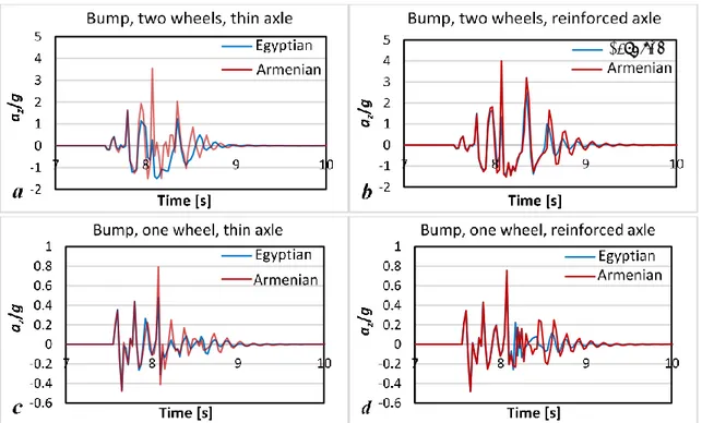
Two running conditions were simulated: bumping with both wheels over an obstacle of 50 mm height at 40 km/h and bumping over the same obstacle at the same speed with a single wheel. Many data were extracted from the analyses, but here a focus on the vertical acceleration of the transported mass is reported, as this parameter determines the stability of the occupant and the risk to be thrown out from the chariot.
Table 1. Masses, elastic constants and damping coefficients introduced in the dynamical simulation.
Egyptian Armenian
Thin axle Reinforced axle Thin axle Reinforced axle
Mp (kg) 80 80 80 80 Mc (kg) 27 33.2 27 33.2 Mw (kg) 7.4 7.4 7.4 7.4 kp (N mm-1) 100 100 - - ka (N mm-1 250 675 250 675 kl (N mm-1) 86 86 - - cp (N s mm-1) 0.771 0.771 - - ca (N s mm-1) 0.862 1.457 1.140 1.903 cl (N s mm-1) 1.046 1.073 - -
Figure 9 shows the vertical acceleration of the transported mass Mp (normalized by the gravity
acceleration) in all of the considered cases. In general, the az is lower with the Egyptian chariot than
with the Armenian one. The advantage is felt mainly in double wheel bumping, where the maximum acceleration with the Armenian chariot is nearly twice as with the Egyptian one. With the reinforced axle the vertical acceleration increases, but not so dramatically. With both of the chariots, however, the double wheel bumping could be a very critical condition, as the vertical inertia significantly exceeded gravity. This suggests that the floor of interwoven leather stripes, which was not considered in this analysis, could have a crucial effect in absorbing the dynamic loads; furthermore, the passage over an elongated obstacle, such as a surface root, could be fatal. The analysis allowed calculating even the forces at the wheels. Their maxima were about 2200 N in vertical direction and 400 in longitudinal direction, obtained in both of the conditions. With these forces, it was calculated that the thin axle could not resist, thus likely the reinforced one was used.
8
1234567890‘’“”
Florence Heri-Tech – The Future of Heritage Science and Technologies IOP Publishing
IOP Conf. Series: Materials Science and Engineering 364 (2018) 012016 doi:10.1088/1757-899X/364/1/012016
Egyptian
Figure 9. Vertical acceleration of the suspended mass with the Egyptian and Armenian chariots:
a) double wheel bumping with thin axle; b) double wheel bumping with reinforced axle; c) single wheel bumping with thin axle; d) single wheel bumping with reinforced axle.
4. Conclusions
The plaster clast of the Mercurago wheel was acquired by laser scanner optical technology. The analysis of the acquired solid allowed obtaining some clues about the construction and the assembly technique. A solid model of the intact wheel was constructed and analyzed by finite element under vertical and lateral forces. The analyses highlighted mainly the weakness of the transversal rods in curve and allowed hypothesizing the anti-wear and anti-friction role of the inserted nave.
Dynamical simulations of the whole chariot in bumping at 40 km/h with single and double wheel were carried out, considering two different chariot configurations (“Egyptian” and “Armenian”) and two axle design solutions. The analyses evidenced the better performance of the Egyptian one in terms of limitation of the vertical acceleration of the occupant, although the double wheel bumping could be a critical condition even for this chariot. Furthermore, the obtained loads on the wheel allowed concluding that the hypothesized solution with the thinner axle was likely unfit.
References
[1] Piggot S 1983 The Earliest Wheeled Transports – From the Atlantic Coast to the Caspian Sea (New York: Cornell University Press).
[2] Rossi S, Chondros T G, Milidonis K F, Savino S and Russo F 2016 Front. Mech. Eng. 11 12–25 [3] Sandor B I 2004 Oxf. J. Archaeol. 23 153–175
[4] Sandor B I 2004 Fatigue Fract. Eng. Mater. Struct. 27 637–646
[5] Rovetta A, Nasri I and Helmi A 2000 Mech. Mach. Theory. 35 1013–31
[6] Mazzù A, Gambari F M, Bodini I, Pasinetti S and Sansoni G 2017 J. Archaeol. Sci. Rep. 15 138– 149
[7] Green D W, Winandy J E and Kretschmann D, Wood handbook-Wood as an engineering material Gen. Tech. Rep. FPL–GTR–113. Madison, WI: U.S. Department of Agriculture, Forest Service, Forest Products Laboratory p 4-1