High-index-contrast grating reflector with beam
steering ability for the transmitted beam
Luca Carletti, Radu Malureanu, Jesper Mørk, and Il-Sug Chung*
DTU Fotonik, Department of Photonics Engineering, Technical University of Denmark, DK-2800 Kgs. Lyngby, Denmark
Abstract: High-index contrast grating mirrors providing wave front control of the transmitted light as well as high reflectivity over a broad bandwidth are suggested and both numerically and experimentally investigated. General design rules to engineer these structures for different applications are derived. Such grating mirrors would have a significant impact on low cost laser fabrication, since a more efficient integration of optoelectronic modules can be achieved by avoiding expensive external lens systems. ©2011 Optical Society of America
OCIS codes: (140.7260) Vertical cavity surface emitting lasers; (050.6624) Subwavelength
structures; (140.3570) Lasers, single-mode. References and links
1. C. F. R. Mateus, M. C. Y. Huang, L. Chen, C. J. Chang-Hasnain, and Y. Suzuki, “Broad-band mirror (1.12-1.62 µm) using a sub-wavelength grating,” IEEE Photon. Technol. Lett. 16(7), 1676–1678 (2004).
2. M. C. Y. Huang, Y. Zhou, and C. J. Chang-Hasnain, “A surface-emitting laser incorporating a high-index-contrast subwavelength grating,” Nat. Photonics 1(2), 119–122 (2007).
3. I.-S. Chung, J. Mørk, P. Gilet, and A. Chelnokov, “Subwavelength grating-mirror VCSEL with a thin oxide gap,” IEEE Photon. Technol. Lett. 20(2), 105–107 (2008).
4. I.-S. Chung, V. Iakovlev, A. Sirbu, A. Mereuta, A. Caliman, E. Kapon, and J. Mørk, “Broadband MEMS-tunable high-index-contrast subwavelength grating long-wavelength VCSEL,” IEEE J. Quantum Electron. 46(9), 1245– 1253 (2010).
5. I.-S. Chung and J. Mo̸rk, “Silicon-photonics light source realized by III-V/Si-grating-mirror laser,” Appl. Phys. Lett. 97(15), 151113 (2010).
6. D. Fattal, J. Li, Z. Peng, M. Fiorentino, and R. G. Beausoleil, “Flat dielectric grating reflectors with focusing abilities,” Nat. Photonics 4, 466–470 (2010).
7. M. G. Moharam and T. K. Gaylord, “Rigorous coupled-wave analysis of planar-grating diffraction,” J. Opt. Soc. Am. A 71(7), 811–818 (1981).
8. M. G. Moharam, E. B. Grann, D. A. Pommet, and T. K. Gaylord, “Formulation for stable and efficient implementation of the rigorous coupled-wave analysis of binary gratings,” J. Opt. Soc. Am. A 12(5), 1068–1076 (1995).
9. L. A. Coldren and S. W. Corzine, Diode Lasers and Photonic Integrated Circuits, p. 438 (Wiley, 1995). 1. Introduction
Recently, high-index-contrast gratings (HCGs) have attracted attention due to their novel characteristics [1–6]. A HCG is a single layer structure with an inscribed one- or two-dimensional sub-wavelength-scale periodic patterning that can provide very high reflectivity over a broad bandwidth [1]. Thanks to a simple and compact structure, HCGs are strong candidates to replace conventional Bragg reflectors, as applied e.g. in vertical-cavity surface-emitting lasers (VCSELs). Also, the ability to strongly modify the grating properties, e.g. via the duty cycle (ratio of a dielectric part width over periodicity), enables the engineering of grating reflectors for a number of different applications. These include simpler epitaxial structure [2], high differential efficiency [2], strong single-transverse-mode operation [3], broad wavelength tunability [4], polarization control [2–5], and light emission into an in-plane silicon photonics chip [5]. Another interesting property of HCGs is that the phase of the reflected or transmitted light can be controlled, while maintaining a high reflectivity. Recent work [6] has demonstrated that the reflected light can be focused by introducing a parabolic
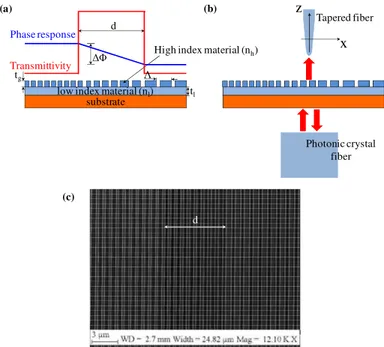
phase front to the reflected beam through the spatial modulation of the grating duty cycle. For integration into VCSELs, phase front control over the transmitted beam is highly interesting, since this would enable to steer the propagation direction of the output light as well as focusing. For example, as illustrated in Fig. 1(a), the light collection from multiple VCSELs to an optical fiber could be facilitated by directly steering the output light from each VCSEL element. This integrated approach would eliminate the need of an external lens for beam collection (Fig. 1(b)). As illustrated in Fig. 1(c), dynamic beam steering would be possible if the refractive index of the HCG could be controlled, e.g. by using the electro-optic effect or the free-carrier plasma effect. These novel functionalities would considerably reduce the lens/optics packaging cost and provide design flexibility in the packaging and free-space optical interconnects. So far, there has been no extensive investigation of the beam steering of the transmitted beam.
Fig. 1. (a) Light coupling from multiple VCSEL elements to an optical fiber by using HCGs. (b) Light coupling by using a lens. (c) Beam propagation angle can be dynamically steered between the solid and dashed lines by changing the refractive index of the HCG.
In this paper, we investigate the fundamental ability of an HCG to manipulate the phase front of a transmitted light beam and formulate useful design rules for the realization of practical structures. Based on these rules, HCG structures are fabricated and experimentally demonstrated to have beam steering ability. Such structures are promising for replacing the output mirror in VCSELs.
The paper is organized as follows. In Section 2, the simulation methods employed to determine the properties of periodic and non-periodic HCG structures are briefly described. In Section 3, the HCG design issues as well as the characterization set-up are discussed. The procedure to design a HCG structure with a linearly varying phase profile that complies with additional application requirements is explained. In Section 4, numerical simulations and experimental characterization results are presented that demonstrate the beam steering ability of HCGs. The theoretical rules are compared with the measurements and good agreement is found.
2. Simulation methods
In this work two different kinds of HCGs are analyzed. First, the transmission and reflection properties of periodic gratings are investigated using the rigorous coupled-wave analysis (RCWA) method [7, 8]. In this approach the periodicity of the structure is exploited to solve Maxwell’s equations. A linear system of equations is built from the boundary conditions. The system solution yields the field distribution, as well as the transmission and reflection characteristics. Extensive simulations are performed to find sets of HCG parameters that provide the targeted transmission phase and transmittivity.
Second, based on RCWA results, grating key parameters are varied within the structure to realize non-periodic HCGs featuring the desired phase profile. It is assumed that the local
(a) (b) Collecting fiber Lens Chip array VCSEL chip (c)
phase response and the local transmittivity of the non-periodic HCG structure depend on the local grating parameters. This assumption is proven later in Section 4. The commercial software COMSOL implementing the finite element method (FEM) is used to simulate the non-periodic structure. Perfectly matched layers are employed at the simulation domain boundaries.
3. HCG design, fabrication, and characterization set-up
The HCG is a one- or two-dimensional photonic crystal slab surrounded by low refractive index materials. The HCG structure investigated in this paper is depicted in Fig. 2. The grating is implemented in the top Si layer of a silicon-on-insulator (SOI) wafer. For VCSEL integration, the grating layer and the substrate layer in Fig. 2(a) can be III-V semiconductors while the low index material layer can be air [2] or oxide [3]. The structural parameters, i.e., grating thickness, tg, low-index layer thickness, tl, grating periodicity, Λ and grating duty
cycle, as well as the refractive indices of the materials employed, nh and nl, determine the
spectral properties of a periodic HCG. Since varying tg is not feasible due to the multiple
etching steps it would imply, here only variations of Λ and the duty cycle are considered. The refractive indices of Si (nh) and buried SiO2 (nl) of the SOI wafer are 3.47 and 1.47,
respectively. From the simulation results, the grating thickness tg is chosen to be 500 nm,
allowing a large transmission phase change ∆Φ at the target wavelength of 1.55 µm. As shown in Fig. 2(a), a non-periodic HCG of width d is located between two different periodic HCGs. The transmittivity within the non-periodic HCG region is designed to be higher than those of the two periodic HCG regions in order to have the light transmitted only from the non-periodic HCG region.
Fig. 2. (a) Schematic of the investigated HCG sample, with the resulting spatially modulated transmission phase response and transmittivity profile. (b) Illustration of characterization set-up. (c) Scanning electron microscope image of the fabricated HCG structure.
Within the non-periodic HCG region, the local phase, Φ(x,y) of the transmitted light is designed to vary linearly by gradually changing the grating structural parameters. In this implementation, the grating periodicity Λ is varied along the x-axis, while the duty cycle is kept constant. Thus, the phase profile becomes x-dependent, Φ(x). If necessary, variation
Phase response
tg
tl
low index material (nl)
substrate
Tapered fiber
Photonic crystal fiber High index material (nh)
Transmittivity (a) (b) (c) x z Λ d d ∆Φ
along the y-axis also can be introduced. In the left and the right periodic HCG regions, different Λ values and duty cycles are applied.
To deflect a beam to a specific angle, θ, the phase response should be linearly varying in space, Φ(x) = αxx, where αx is a proportionality factor and has the unit of rad/m. The steering
angle, θ depends on αx: Assuming a plane wave is recovered just after the HCG, the
transmitted electric field may be expressed in the form E = E0(x)exp[-jk(xsinθ + zcosθ)],
where E0(x) is a slowly-varying power envelope and k = 2π/λ is the wave number at the
wavelength λ. For a fixed z coordinate, the phase of the field is only a function of x: arg(E) =
Φ(x). When the phase in this direction is given by a linearly varying profile, the beam would
be deflected to an angle of θ = sin−1(αx/k). As shown in Fig. 2(a), the total phase difference
between the extremes of the HCG is ∆Φ, and thus the proportionality coefficient is αx = ∆Φ/d.
Substituting this in the expression above to estimate the deflection angle gives
( )
1 sin d k . θ − ∆Φ ⋅ = (1) This equation relates the design parameters ∆Φ, d and the wavelength λ to the steering angle θ achieved by the structure. It is noted that at a certain wavelength, larger steering angles can be obtained by increasing the total phase shift, ∆Φ throughout the structure or by decreasing the grating width, d. It is also seen that for longer wavelengths, i.e. smaller wave number, the beam deflection may increase for a constant ∆Φ/d ratio.The relationship expressed in Eq. (1) will be useful to design HCGs that have to comply with a set of specific requirements which depend on the application. For example, if the HCG is to be employed as the output mirror of a VCSEL, the reflectivity is required to be about 99.5% for lasing, and the non-periodic HCG region size needs to match the mode size that is typically 5-7 µ m [2]. The need to simultaneously fulfill these requirements limits the degree of freedom in controlling the phase response of the grating.
In Fig. 2(b), the characterization setup is depicted. A polarized laser beam with a wavelength of 1.55 µ m is coupled to a photonic crystal fiber. The selected polarization is transverse magnetic (TM) with the electric field vector in the x-axis direction. From the polarization-maintaining photonic crystal fiber with a mode diameter of 10 µm, the beam diverges to a width of about 100 µm at the silica-grating interface. From the transmission side, light is detected using a tapered fiber with small mode dimension (2 µm). In order to avoid the use of additional lens systems to adapt the spot size of the input light to the non-periodic HCG region size, d, the transmittivity of the sample is modulated as shown in Fig. 2(a). The total structure, including both non-periodic and periodic regions, is a square of 400 × 400 µm2 that covers all the area illuminated by the incident light.
The fabrication is performed on an SOI wafer. Electron-beam lithography is performed in order to create a mask for the dry etching of grating grooves. To ensure a high selectivity and anisotropy, a Bosh process is employed for the dry etching: The etching is cyclic, each cycle having two parts. In the first part, the sample surfaces are passivated by depositing a chemically inert layer obtained from C4F8. In the second part of the cycle, the etching takes
place using a plasma of C4F8 and SF6. During this part, the passivating layer is removed by
ion bombardment, leaving reactive surfaces that are chemically etched. Figure 2(c) shows an example of a fabricated sample.
4. Results and discussion
Simulation results for the dependence of HCG transmittivity and phase on key grating parameters are shown in Fig. 3. The results were obtained by using the RCWA method. In the HCG design, to facilitate the device characterization, the transmittivity value targeted for the non-periodic HCG region is 13.9 ± 1.7%, while in the periodic HCG regions the transmittivity is lower than 0.3%. To accomplish this, the duty cycle in the non-periodic HCG region is chosen to be 53%. With the parameters obtained from Fig. 3(b), the maximum phase shift that can be obtained, while keeping within the range of allowed transmittivity values, is
approximately ∆Φ = 150°. The non-periodic HCG region is designed to have a width, d, of 6.2 µm. The corresponding steering angle of the final device, estimated using Eq. (1), is θ = 5.98°.
Fig. 3. (a) Contour plot of transmittivity (in dB, color scale) versus wavelength and grating period. The vertical black line corresponds to a wavelength of 1.55 µm. (b) Phase and transmittivity as a function of grating periodicity, Λ, for a wavelength of 1.55 µm.
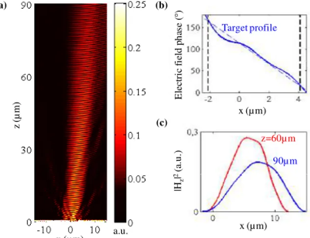
Fig. 4. Simulation results for HCG grating designed for beam steering. (a) Evolution of
magnetic field intensity profile (|Hz|2) with distance z from the HCG top surface, located at z =
0. (b) Phase profile of the electric field (Ex) at z = 10 µm. The black dashed lines delimit the
projection of the non-periodic HCG region assuming negligible beam divergence and θ = 5.5°.
(c) Magnetic field profiles (|Hz|2) at z = 60 µm and 90 µm.
Figure 4 shows the results of a FEM simulation of the designed non-periodic HCG structure. The simulated structure is the same as the one depicted in Fig. 2. The light source is a plane wave with a Gaussian power envelope and a wavelength of 1.55 µm. Its full width at half maximum (FWHM) is 30 µ m. From Fig. 4(a) and 4(c), the deflection angle, θ is 5.5°, which is in good agreement with the value predicted by Eq. (1). In Fig. 4(b), the phase of the electric field, Φ(x) measured at z = 10 µm matches well the desired phase profile. The slight deviation from the targeted linear phase profile can be attributed to the interference with the diffracted near field: The transition from the near- to the far-field occurs around z~d2/λ = 25 µ m [9]. The total phase shift, ∆Φ measured in Fig. 4(b) is approximately 150° as designed in Fig. 3(b). These good agreements in θ and ∆Φ found between the RCWA-based periodic simulations and the FEM-based non-periodic simulations validate our assumption that local transmission phase is determined by local grating parameters.
Period Λ (nm) T ra n sm itti v ity (% ) P h a se ( ° ) (b) P er io d Λ (n m ) (a) Wavelength (µm) dB Fig. 3(b) 500 600 700 800 900 1000 1100 1200 -90 -60 -30 0 30 60 90 0 10 20 30 40 x (µ m) z (µ m ) (a) (b) x (µ m) |H z | 2(a .u .) (c) z=60µ m 90µ m E le ct ri c fi el d p h as e ( °) x (µ m) Target profile a.u.
Fig. 5. Measured beam profiles at different distances from the HCG. Markers (hollow dots) are measurements and solid lines show corresponding fitted Gaussian profiles.
The non-periodic HCG with a linearly varying phase profile, simulated in Fig. 4, has been fabricated using the procedure outlined earlier. Using the setup described in Section 2, the power of the light transmitted through the grating is measured along the x-axis direction and at different distances, z, from the HCG. In order to avoid the complex transient fields from the near- to the far-field, it is measured from z = 30 µ m. The measurement results are presented in Fig. 5. The spatial position of the peak clearly shifts as the beam propagates further from the grating, indicating beam deflection. The measurements are fitted to a Gaussian distribution. The difference between the fitted curves and the measurements may have several explanations. First of all, due to beam steering, the beam profile would not be exactly Gaussian along the x-axis as the wave front would be tilted by an angle θ with respect to the
x-axis. Furthermore, some uncertainty is introduced by the setup. The error in the position of the fibers was ± 0.5 µ m. From the Gaussian fits, the peak is displaced by ~7 µ m from the first to the last measurements taken at a distance of 30 µ m and 90 µ m from the HCG, respectively. The measured steering angle is θ = tan−1[7/(90−30)] = 6.65° ± 0.71°. This value is in excellent agreement with the theoretical values for the considered grating design, including the prediction by Eq. (1).
5. Conclusions
We have demonstrated that high-index-contrast grating (HCG) reflectors can be used to manipulate the transmitted beam, while simultaneously maintaining high reflectivity for the incident beam. Fabricated structures with a non-periodic HCG region show a beam deflection of ~6°, in excellent agreement with numerical simulations. Basic design rules to realize gratings that impose an engineered phase front to the transmitted beam are explained and their applicability is demonstrated by comparison with simulation and characterization results. The ability of these HCGs to feature high reflectivity as well as wave front control can be advantageous for many applications, such as low cost laser fabrication. Furthermore, this approach can be generalized to obtain different phase profiles from the grating, broadening the set of possible applications as well as opening the possibility for integration of additional functionalities in compact and cheap devices.
x (µm) P o w er (n W ) z =30 µm 45 µm 60 µm 75 µm 90 µm