RICERCA DI SISTEMA ELETTRICO
World status of the SMR projects
L. Paparusso, M.E. Ricotti, M. SuminiReport RdS/2011/166 Agenzia Nazionale per le Nuove Tecnologie,
WORLD STATUS OF THE SMR PROJECTS
L. Paparusso, M.E. Ricotti – Politecnico di Milano, M. Sumini – Università di Bologna Dienca Settembre 2011
Report Ricerca di Sistema Elettrico
Accordo di Programma Ministero dello Sviluppo Economico – ENEA Area: Governo, Gestione e sviluppo del sistema elettrico nazionale
Progetto: Nuovo nucleare da fissione: collaborazioni internazionali e sviluppo competenze in materia nucleare
CIRTEN
Consorzio Interuniversitario per la Ricerca TEcnologica Nucleare
°POLITECNICODIMILANO
DIPARTIMENTO DI ENERGIA, Sezione INGEGNERIA NUCLEARE-CeSNEF
*UNIVERSITA’ DI BOLOGNA
DIENCA - Dipartimento di Ingegneria Energetica, Nucleare e del controllo ambientale
World status of the SMR projects
L. Paparusso°, M.E. Ricotti°, M. Sumini*
CERSE POLIMI RL 1351/2011
Milano, Settembre 2011
Lavoro svolto in esecuzione della linea progettuale LP1– punto B4 AdP MSE‐ENEA “Ricerca di Sistema Elettrico” - PAR2008-09
Rapporto “World status of the SMR projects” LP1.B4 - 2 - CERSE-POLIMI RL-1351/2011 INDEX EXECUTIVE SUMMARY... ‐ 3 ‐ 1 INTRODUCTION ... ‐ 4 ‐ SMR projects ‐ Classification by Type... ‐ 8 ‐ 1.1 LWR (PWR) ... - 8 - 1.2 LMFBR ... - 8 -
1.3 “Exotic” or “Unconventional” Projects ... - 8 -
1.4 MSR ... - 8 - 2 SMR ‐ Classification by project ... ‐ 9 ‐ 2.1 Nuscale (PWR-Integral)... - 9 - 2.2 mPower (PWR-Integral) ... - 14 - 2.3 IRIS (PWR-Integral)... - 18 - 2.4 SMART (PWR-Integral)... - 21 - 2.5 KLT-40 (PWR-Loop, Barge)... - 26 - 2.6 PHWR-220... - 30 - 2.7 VBER-300 (PWR-loop)... - 34 -
2.8 ENHS (LMFBR- PbBi cooled)... - 39 -
2.9 BREST-300 (LMFBR, Lead cooled)... - 47 -
2.10 Hyperion (LMFBR, PbBi cooled)... - 50 -
2.11 SVBR 100 (LMFBR, sodium cooled) ... - 53 -
2.12 4S (LMFBR, sodium cooled)... - 56 -
2.13 Candle (LMFBR, sodium cooled)... - 59 -
2.14 HTR-PM (Gas cooled)... - 61 -
2.15 Flexblue (PWR underwater) ... - 65 -
Rapporto “World status of the SMR projects”
LP1.B4 - 3 - CERSE-POLIMI RL-1351/2011
E
XECUTIVES
UMMARYThe document presents the current status of development and, in some cases, deployment of Small-Medium size, Modular Reactors worldwide.
In the recent years, an increasing interest has grown around the concept of “smaller size” reactors. Albeit this concept is already known, i.e. nuclear reactors of few hundreds MWe power were built in the 60’s and the 70’s and also in Far East (e.g. India) in recent past times, the paradigm of the economy of scale hence of “larger size” reactors has largely overwhelmed this original approach since long time. That led, for example, to conceive-develop-deploy 1400-1600 MWe NPPs (e.g. APR-Korea, EPR-France).
Some issues call into question the assumption of the general and absolute validity of the paradigm: the availability of funding to sustain the construction effort of such a big endeavor, the associated risk of costs increase, e.g. in case of construction-operation delays, the suitability of such large size plants for poorly interconnected electrical grids, the availability of manufacturers-suppliers of large components or critical elements (e.g. tube bundles).
Moreover, the concept of modular construction already adopted in some Generation III reactors (e.g. AP1000-USA) and very likely leading to lower costs and better quality and safety (e.g. due to in shop manufacturing), is supposed to be better implemented in SMRs than in Large Reactors.
These are the assumptions or the believed factors underpinning the SMR approach, together with a claimed superior safety and, in some cases, a better proliferation resistance.
Several countries (including France in the very recent months) begun studying, developing and in few cases deploying, their domestic SMR project. IAEA as well is active in this field, with several coordinated research programmes under way.
The list and essential description of the different SMRs, herein reported, show the increasing interest towards this type of reactors, covering several technologies (from PWR to FBR and MSR). The feasibility, affordability and success of such an approach are yet to be proven. The financial and safety constraints, recently strengthened by the global economic crisis and the Fukushima event, could give to the SMR industrial strategy a real opportunity.
Rapporto “World status of the SMR projects”
LP1.B4 - 4 - CERSE-POLIMI RL-1351/2011
1 INTRODUCTION
Light water reactor systems for propulsion were the forerunner of commercial nuclear power systems we see nowadays. Light-water reactors (LWR) were chosen because of their simplicity and compactness at this small scale. U.S. Air Force and Army also started a nuclear power program. From 1946, the Air Force studied the use of small nuclear reactors to power long-range bombers, but this application proved too difficult and politically unattractive and was terminated in. The Army Nuclear Power Program ran between 1954 and 1976 and led to the construction of eight reactors. These included six 1–2MWe pressurized water reactors (PWR), one 10MWe barge-mounted PWR reactor and one 0.5MWe gas-cooled reactor (GCR).
Fig.1 ‐ Progression of power level for the commercial nuclear power plants built in the United States (Energy Information Administration, 2008).
The Army program was discontinued because of the poor economics of the nuclear plants compared to cheaper alternative fuels available at that time. The early commercial reactors commissioned in the late 1950s and early 1960s were essentially scaled-up versions of the naval power plants. The 60MWe Shippingport plant began operation in 1957, the 200MWe Dresden plant in 1960, and the 250MWe Indian Point Unit 1 plant in 1962. Due to the rapidly growing demand for electricity, the high level of confidence in the safety of nuclear plants, and the economic principle of ‘‘economy of scale,’’ reactor size began to grew up till 1300MWe. Much of this growth occurred over a 15-year period without the benefit of operating experience from smaller predecessors of these new large-size reactors. Fig. 1 shows the progression of power level for the commercial nuclear power plants built in the United States (Energy Information Administration, 2008). Analyzing this progression one can notice that power plants commissioned before 1973 were SMRs by IAEA’s definition.
Rapporto “World status of the SMR projects”
LP1.B4 - 5 - CERSE-POLIMI RL-1351/2011
The apparent anomaly in the growth trend in 1976 was the startup of the demonstration gas-cooled reactor, Fort St. Vrain. No subsequent gas-cooled reactors have been built in the U.S. As plant sizes grew and as operational issues began to moderate the industry’s confidence in the ultimate safety of the plants, more stringent safety requirements were imposed. This fact led to a growing complexity in the plant designs, adding redundant safety and auxiliary systems. This escalation of plant complexity contributed to rapidly increasing costs, construction and operational delays, licensing delays, and eventually decreased confidence by the owners and lenders in the profitability of the plants. Almost every reactor was built to accommodate the interests of individual customers, making every reactor a “one of a kind” construction process. Obviously this contributed to increased licensing, construction, and operational complexities. These and many other factors contributed to the eventual demise of the first nuclear era, which was punctuated by the accident at the Three Mile Island (TMI) plant in 1979.
Interest of many countries to the development and application of SMRs reactors continued as continued operation, construction of new small power plants, and progress in design and technology development. SMRs designers explored innovative design approaches to reach a higher level of plant safety, economics, and proliferation resistance. These facts ensure that such reactors could competitively meet the needs of potential users in those markets that cannot be effectively served by the economy of scale nuclear deployments. The potential SMRs users are diverse, spacing from small towns and industrial sites in off-grid locations to growing cities in developing countries. There’s also the possibility to use such reactors for non-electrical applications in deregulated markets. The requirements of these user groups are also diverse, ranging from small capital outlay and incremental capacity increase to autonomous operation, advanced cogeneration options and long refueling interval. To facilitate SMRs development, the IAEA is carrying out new activities for SMRs that include:
-Design and deployment strategies to overcome loss of economies of scale, for example, advantages in reduced design complexity, modularity and accelerated learning;
-Definition of investor requirements for innovative SMRs and consolidation of methodologies to help public and private investors in developing countries assess the overall potential of innovative SMRs;
-Continuous re-examination and quantification of needs for SMRs based on a country-independent model which will be developed to support such quantification;
-Dynamic simulations of energy systems with innovative SMRs.
The potential for small and medium size reactors, SMRs is under study in the USA, Japan, Russia and other countries. France's naval construction firm DCNS together with Areva, Electricité de France, EDF and the Commissariat a L'Energie Atomique, CEA research organization decided to set up a joint study of DCNS' submerged reactor. it could provide wide energy for coastal locations all over the world.
The concept is called Flexblue and involves a cylindrical vessel about 100 meters long and 15 meters in diameter that encase a complete power plant producing from 50 to 250MWe.
The cylinder with the power plant inside would be lowered to the seabed at a depth of 60 or 100 meters, at a site between 5 and 15 kilometers from the shore.
Undersea cables would bring the electricity to customers at the coast much like offshore wind turbines. It is estimated that ¾ of the world's population lives within 80 km of 'the sea.
A submerged power plant unlike a floating one would not be vulnerable to earthquakes, tsunamis, or floods, and would be less vulnerable to voluntary attack.
Rapporto “World status of the SMR projects”
LP1.B4 - 6 - CERSE-POLIMI RL-1351/2011
It would also have an "unlimited" source of coolant due to the sea all around and the plant's footprint would be minimal.
The cylindrical vessel obviates the need for civil engineering ,which has proved challenging at Areva's and EDF’s under construction nuclear plants in Finland and France and it means the plant can be built in a factory in a modular way with standardized components. For safety issues it can be brought till the surface and taken to a DCNS’ shipyard for repair.
It could be refueled in the same way, and at end of life be repatriated to the shipyard for decommissioning, which would resemble the decommissioning of nuclear submarines, Areva has already begun developing, a Small Modular Reactor, or SMR, of about 100MW based on the experience of its Technicatome in building reactor plants for submarines and France's nuclear-power aircraft carrier: the Charles De Gaulle. Such a reactor could be embarked in a Flexblue power plant.
The market for SMRs is estimated at about 200 units worldwide over the next 20 years, Flexblue could grab a significant share of that market.
DCNS’ shareholders are the French stare at 74 percent. defense firm Thales at 25 percent and employees at 1 percent.
AREVA, a world leader in nuclear energy has launched a program to study small reactors rated at 100 MWe with a view to rounding out its range of third generation reactors comprising EPR, ATMEA and Kerena types. This study draws-on AREVA's expertise in small shipboard reactors to assess the product's feasibility and market potential.
U.S. government nowadays gives to nuclear energy an important role. Nuclear power’s objective is to assist in the revitalization of the U.S. industry through R&D. Developing these technologies through R&D could help accelerating the deployment of new plants in the short term, supporting development of advanced concepts for the medium term, and promoting design of revolutionary systems for the long term. This target will be achieved in partnership with industry to the maximum extent possible. Elements of nuclear energy’s strategy in this area include:
• Assist industry to improve light water reactors using existing technologies and designs. • Explore advanced LWR designs with improved performance.
• Research and develop small modular reactors that have the potential to achieve power’s objective is to assist in the revitalization of the U.S. industry through R&D.
Smaller reactors have the possibility to be built in modules. This might help reduce the capital costs associated with large plants. It’s always possible to incrementally “step up” to larger electrical capacities while generating revenue and repaying initial debts.
To help SMRs’ development President Obama has earmarked $500 million over the next five years for SMR research and demonstration projects. Moreover Energy Secretary Steven Chu predicts that an SMR will be producing electricity by the end of this decade.
Congressmen also included in their speech to the Senate issues about SMRs (e.g. Sen Mark Udall, Colorado; Jeff Bingaman, New Mexico; Congressman Jason Altmire, Pennsylvania).
IAEA published a document (Design Features to Achieve Defence in Depth in Small and Medium Sized Reactors, Vienna 2009) showing SMRs future and describing the most important project.
Rapporto “World status of the SMR projects”
LP1.B4 - 7 - CERSE-POLIMI RL-1351/2011
Looking at Fig.2 it is possible to understand which prospective exist for small-size reactors, having an idea of the time scale connected to the major projects.
Not all of the project showed in figure are going to be licensed. Brown color indicates project in a more advanced stage of development.
Fig.2 – Time schedule for the development and possible deployment of innovative SMRs, with and without on-site refuelling.
Rapporto “World status of the SMR projects”
LP1.B4 - 8 - CERSE-POLIMI RL-1351/2011
SMR PROJECTS - CLASSIFICATION BY TYPE
1.1 LWR (PWR)Pressurized water reactors (PWRs) constitute a majority SMRs. In a PWR the primary coolant, high pressure light water, flows in the reactor core where it is heated and, passing through a steam generator, it transfers its thermal energy to a secondary system where steam is generated. This steam flows to turbines which provides electrical energy. Small PWRs were originally designed to serve as nuclear propulsion for nuclear submarines.
In this category we can find: Nuscale, mPower, IRIS, SMART, KLT-40
1.2 LMFBR
LMFR reactor uses liquid metal as primary coolant. Liquid metal cooled reactors were first adapted for nuclear submarine use but have also been extensively studied for power generation applications. They don't need to be kept under pressure, and they allow a much higher power density than
traditional coolants. Difficulties of inspection and repair of a reactor immersed in opaque molten metal, corrosion, production of radioactive activation products are the most discussed issue. The most significant LMFBR SMR project is Toshiba’s 4S.
1.3 “Exotic” or “Unconventional” Projects
Under the name of “Exotic” projects it is possible to find out innovative and non conventional reactor projects as PbBi Hyperion (US) or CANDLE (JP) or the new French project of an underwater Integral PWR named Flexblue. These projects usually have different fuel cycle process (e.g. sealed core). 1.4 MSR In the MSR, the fuel is a molten mixture of lithium and beryllium fluoride salts with dissolved enriched uranium, thorium or U‐233 fluorides. Heat is transferred to a secondary salt circuit and thence to steam. It is not a fast neutron reactor, but with some moderation by the graphite is epithermal. The fission products dissolve in the salt and are removed continuously in an on‐line reprocessing loop and replaced with Th‐232 or U‐238. MSRs have a negative temperature coefficient of reactivity, so will shut down as temperature increases beyond design limits.
Rapporto “World status of the SMR projects”
LP1.B4 - 9 - CERSE-POLIMI RL-1351/2011
2 SMR - CLASSIFICATION BY PROJECT
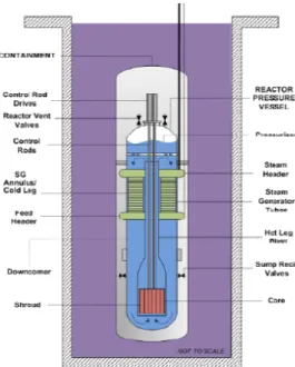
2.1 Nuscale (PWR-Integral)
Figure 3.1.1 Nuscale module layout
NuScale
Power 160MWt 45MWe
Dimension 2.7m Diam x13.7m Height Vessel Thickness 7.6cm
Primary Pressure <12.7MPa Primary Flow 600kg/s Layout 12x in pool
Weight 300 tons
Transportation Barge, truck or train
Fuel Standard LWR fuel in 17 x 17 configuration
Enrichment 4.95% SG Length 22.3m
Secondary Flow 70kg/s Feedwater Temp. 150°C
Rapporto “World status of the SMR projects”
LP1.B4 - 10 - CERSE-POLIMI RL-1351/2011
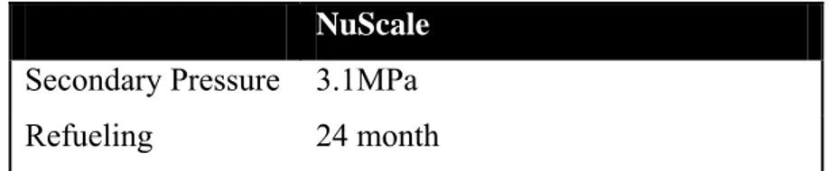
NuScale Secondary Pressure 3.1MPa
Refueling 24 month
A single NuScale module produces 45,000 kilowatts of electricity. Heat is transferred from primary circuit, the core, to the secondary one by steam generators, integrated in the vessel itself. Produced steam is sent to a steam turbine connected by a single shaft to the electrical generator. NuScale power plant will operate at full power for about 95% of the time. This makes it a really reliable generation system.
Fig 3.1.2 NSS and BOP of a Nuscale module
Because of its modular design it is possible to join each NuScale, self contained anyway and independent from the others, in a multi-module configuration. However, all are managed from a single control room.
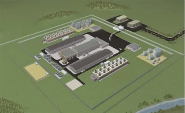
A plan view of a layout made of a 12 module array with a total capacity of 540 MW(e) is shown in Figure 3.1.4. The design layout shows a building which houses the pool containing the modules, a turbine building, and a separate refueling building which contains an area used as the spent fuel storage pool.
Rapporto “World status of the SMR projects”
LP1.B4 - 11 - CERSE-POLIMI RL-1351/2011
Figure 3.1.3 Nuscale 12 unit layout
Figure 3.1.4 Schematic view of 540MW layout
There are multiple barrier between fuel and environment, starting from cladding, to the reactor pressure vessel measures that sits in a containment vessel. This entire module operates inside a pool built below grade. No pumps are needed to move water inside the reactor, because of natural circulation. This enhances safety and cut off the possibility of pump failures.
Secondary circuit is a standard 45MWe cycle, so, after steam passes through the turbines, it is cooled in a condenser and returns to the steam generator inside the reactor. There is the possibility
Rapporto “World status of the SMR projects”
LP1.B4 - 12 - CERSE-POLIMI RL-1351/2011
to use steam, after it passes through the turbines, for low temperature, low pressure applications requiring heated water.
It is possible to use NuScale system only to produce steam, using its 160MW thermal, for industrial applications, such as district heating for communities, large facilities and installations, or to
synthesize fuels.
Enhancing safety means, in a NuScale module, working with passive safety systems using natural circulation for emergency feedwater cooling, decay heat removal, and containment cooling. In this way, primary pipes and pumps are avoided as well as failures associated with pipe breaks and pump failures. This systems also operate without external power and there’s no need for emergency power on site or off site. In case of a simultaneous rupture of any or all of the reactor piping internal the containment vessel is capable of resisting to deriving pressure transient.
For what concerns earthquakes, the pool grants particular resistance to seismic. The possibility of a big radioactive material releasing is very low compared to the large-scale reactors: each 45 MWe NuScale power module uses about 4% of the fuel inventory of a big-size nuclear reactor.
the reduced amount of piping, low pressure and simpler design are a contribution to safety enhancing.
Security must also be stressed in a NuScale plant. The most important features are:
• Lower reactor building profile.
• The reactor and containment vessel are located in a water-filled pool underground creating a low profile and protected target.
• NuScale high pressure containment vessel is capable of seven times the internal pressure of conventional containments.
• Submerging the reactor further reduces post-impact jet fuel fire concerns.
• No external power is needed to cool the core, which limits plant vulnerability and loss of off-site power is not an issue.
The NuScale containment vessel has several characteristics distinguishing it from other existing containment systems designs.
During standard power operation, an insulating vacuum is maintained in the containment providing a big reduction of heat loss from the reactor vessel. Thanks to this solution, the reactor vessel does not need surface insulation.
Furthermore, when safety valves vent steam into containment atmosphere, the deep vacuum improves steam condensation rates. Further, in case of a severe accident, eliminating containment air grants a security margin against the creation of a combustible hydrogen mixture (no need for hydrogen recombiners), and eliminates corrosion and humidity problems inside containment. Plus, thanks to the reduced dimensions, it can sustain a pressure greater than 3.4 MPa (500 psia). In this way, the final pressure in the event of a small LOCA will always be below the containment design pressure.
Every NuScale module has its own set of passive safety systems and it is immersed in a pool that can absorb decay heat after a shutdown for 72 hours granting a bulk fluid temperature of 93°C.
Rapporto “World status of the SMR projects” LP1.B4 - 13 - CERSE-POLIMI RL-1351/2011 Decay heat must reach the pool, so each NuScale is designed with two redundant passive systems providing a path to the containment pool: the Decay Heat Removal System (DHRS) and the Containment Heat Removal System (CHRS). To transfer heat generated to the containment pool, the DHRS uses the two steam generator tube bundles. Before natural circulation starts the feedwater accumulators provide initial water flow. Figure 3.1.4. Schematic CHRS scheme The CHRS, shown in Figure 3.1.4, acts in case the steam generator tube are not available. It works opening the vent valves on the reactor head. Steam of the primary system is vented into the containment and it condenses on the containment surfaces. Recirculation valves are then opened when the liquid level rises above the top of the recirculation valves, to start natural circulation from the sump through the core and out of the reactor vent valves. The effect of these systems combined together eliminate Large Break Loss of Cooling Accident (LOCA) by design. Even in case of design basis small break LOCA, there is no scenario in which the core is exposed, as it will be under water all the time. Thus cooling pathways are always available to remove decay heat.
Rapporto “World status of the SMR projects”
LP1.B4 - 14 - CERSE-POLIMI RL-1351/2011
2.2 mPower (PWR-Integral)
Figure 3.2.1 mPower reactor core
mPower
Power 425MWt 125MWe Dimension 4.5mx22m reactor vessel Reactor Containment 28m Diam x 46m H; 1.5m
thickness; concrete Foundation 47m Reactor Building 85mx73mx15m
Weight 500 tons
Transportation Barge, truck or train
Fuel Standard LWR fuel, 17 x 17 N° Fuel Assemblies 69
Rapporto “World status of the SMR projects”
LP1.B4 - 15 - CERSE-POLIMI RL-1351/2011
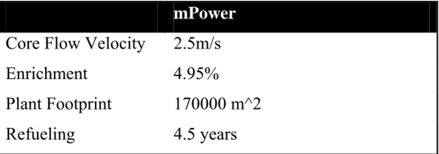
mPower Core Flow Velocity 2.5m/s
Enrichment 4.95% Plant Footprint 170000 m^2
Refueling 4.5 years
Each 125MWe reactor is produced in a factory, cost about half a billion dollars, and could be built and installed, in multiples of two or four reactors, in only three years. mPower initial site designs show that the reactor should be installed in group of two or four modules, for a total of 250-500 MWe of generation capacity with a footprint of 170000 square meters for the twin configuration. mPower is designed with an integral layout, that means the vessel holds all the components of the nuclear steam supply system. Fuel rods are on the bottom of the reactor, to make refueling easier. The reactor provides 425MWt, or 125MWe and it is designed to be air-cooled, for a cycle efficiency of 31%. In case of a water-based heat sink, cycle efficiency increases and power generation reaches 136MWe.
A difference between mPower and conventional PWRs occurs in SG configuration: in conventional PWRs primary coolant flows inside the tubes and secondary coolant flows all around them. In mPower, the primary coolant flows outside while secondary coolant is in the tubes. This is necessary thinking at its layout, and comes from experiences in naval propulsion.
Between SG and the reactor, are the control rod system; there’s one control rod per fuel assembly and there’s no soluble boron to control reactivity, to make the whole system simpler.
Rapporto “World status of the SMR projects”
LP1.B4 - 16 - CERSE-POLIMI RL-1351/2011
The integrated layout makes the safety case simpler as there are no primary loop penetrations, except for a 2in-diameter clean-up valve at the top of the reactor. In this way we find no large piping going put of the primary, so LOCA possibilities are lowered by design. It must be stressed that due to the height of the unit, a design-basis accident would not drain the reactor core. Gravity fed systems are proposed to remove decay heat from the reactor.
The fuel has a single five-year burn, instead of the standard three-burns as it happens in PWRs; at the end of fuel life the entire core is replaced in one load. Refueling would be expected to last about a week. A nearby spent fuel pool can store 12 cores, enough for a 60-year lifetime. During refueling it would also be possible to substitute the steam generator and inspect it while a new steam generator is put in operation, without lose time and money. This could be done alternatively every 5 years.
The project requires the core and reactor containment to be built entirely underground, to enhance security.
Figure 3.2.3 mPower containment
Transportation is a key point: mPower vessel size is the largest unit that can go by rail from the factory, plus the reactor is small enough to be forged in North America, instead of Europe or Japan . almost the whole unit would be assembled in factories, rather than in situ, granting higher standards and low costs; the construction process results more similar to a combined-cycle gas turbine.
Designers plans are to invert the standard nuclear construction process.. the new approach is to build the power plant first and then bring the reactor on site and connect it to the plant. So it’s possible to build modules in parallel with field activity to shorten construction times. On the contrary in a large plant it’s necessary to build the reactor first and then the rest of the power plant.
Rapporto “World status of the SMR projects”
LP1.B4 - 17 - CERSE-POLIMI RL-1351/2011
Different mPower reactors can be joined in a single power station to provide multiples of 125MWe power. Single modules can be twinned to drive a single turbogenerator this process gives the possibility to fit electricity layout on customer needs: 500-750MWe, 125-250MWe etc. It’s possible to go up till 1000MWe or above. The capacity can be added in steps, thanks to the modularity of the base project, rather than all at once, allowing stepwise capital investment
After licensing process, according to estimated time schedule, first startup could be around 2018-2019.
Rapporto “World status of the SMR projects”
LP1.B4 - 18 - CERSE-POLIMI RL-1351/2011
2.3 IRIS (PWR-Integral)
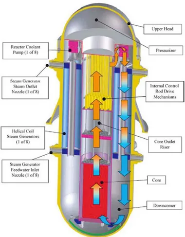
Figure 3.3.1 IRIS core and primary flow path
IRIS Power Reactor Vessel Outlet Condition Coolant Weight 1000MWt 335MWe 6.2m x 22.2m H; 25cm thickness 330°C Light water 1070 ton
Reactor Containment 25m D; 4.4cm thickness; steel Reactor Building 50mD x 39mH
Steam Generator 1149m^2*8 units; 8,5m height Steam Pump 1600 kg, 1800 rpm, 4500 kg/s Steam Flow 502.8kg/s
Rapporto “World status of the SMR projects”
LP1.B4 - 19 - CERSE-POLIMI RL-1351/2011
IRIS Steam Pressure 5.8MPa Condenser Pressure 0.005MPa
Transportation Barge or special truck Fuel Design 17x17 assemblies Enrichment 4.95% Plant Footprint 358080 m^2
Refueling 3-3.5 years
IRIS is a light water reactor with a modular integral primary system configuration with a net electrical output of about 300 MWe/module. Its design is characterized by four milestones: enhanced safety, improved economics, proliferation resistance and waste minimization.
Integral design means that steam generators, pumps, and pressurizer are located inside the reactor vessel. In this way is it possible to reach enhanced safety standard, due to the elimination of external loop piping, the source of accidents involving a large loss of coolant. Thanks to this configuration it is allowed the use of a small, high design pressure, spherical steel containment resulting in a great reduction in the size of the nuclear island. Safety-by-design approach aim to eliminate some accident initiators starting from the very beginning, the design stage, or when elimination is not possible, lowers accident consequences and probability. This enhances defense in depth and lowers core damage frequency for example; it also allows IRIS to claim no need for an emergency response zone. There are also active and passive safety systems.
Rapporto “World status of the SMR projects”
LP1.B4 - 20 - CERSE-POLIMI RL-1351/2011
Among active systems it’s possible to find: stand-by diesel generators, startup feedwater system to fill the SG to remove heat from the core, boron injection systems. Passive systems are simpler and more economic: pressure suppression system, emergency heat removal system (natural circulation+ heat exchanger), automatic depressurization system.
This new safety approach eliminates accidents scenarios like: LOCA, control rod ejection, feed line break, steam line break, SG tube rupture.
The entire reactor is the pressurizer; pressure is maintained using sprayer and the core heat. Each reactor has eight once-through helical steam generators, placed inside the reactor vessel near the walls.
Reactivity coefficients remain negative throughout all reactor life. Burnable poisons are added to the fuel to flatten neutron flux. Reactivity is controlled both with boron and control rods
Shut down maintenance is scheduled every four years because of its simplified design, with less pumps, valves, pipes, and other components. There’s also the possibility to operate maintenance while reactor is operating thanks to, modular, easily replaceable components.
The basic feature of a modular reactor is to match the construction of generating capacity to a utility’s future power requirements. IRIS offers flexibility, with a defined construction time of two to three years. This makes IRIS a good economic option to produce electricity power required, instead to have bigger power plants with the consequent higher investments and difficulty in injecting big electrical power on the grid.
It is also possible to establish a process lead to desalination of water. The development of a region is usually based on two main components: water and energy. An analysis was set up to study the possibility of building three IRIS modules to produce the amount of energy needed plus 7 reactor used for desalination of water in the Sonora region.
A key step in the R&D phase for SMR concepts as well as for IRIS, is the testing phase of the reactor safety features. This effort is currently under way in Italy: the SPES-3 facility will represent a reference facility worldwide for such a new type of reactors.
Rapporto “World status of the SMR projects”
LP1.B4 - 21 - CERSE-POLIMI RL-1351/2011
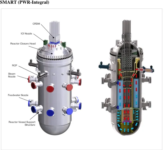
2.4 SMART (PWR-Integral)
Figure 3.4.1. SMART reactor
SMART
Type Integral PWR
Power 330MWt 100MWe Core Dimensions 5.3m D x 15.5m H Desanalination (ton/day) 40,000
Design life 60 years
Assembly type 17x17 square FA Fuel material UO2
Active core length 2.0 m Design pressure 17MPa
Rapporto “World status of the SMR projects”
LP1.B4 - 22 - CERSE-POLIMI RL-1351/2011
SMART Operating pressure 15MPa Design temperature 360 °C Core outlet temp. 323 °C Core inlet temp. 296 °C Minimum flow rate 2090 kg/s
Enrichment Max 5%
Core Damage Frequency 10^-6 N° Steam Generator 8
Stram Generator Inlet 323 °C (30°C superheating)
Refueling 36 months
In 1996 Korea Atomic Energy Research Institute launched a project to develop an SMR based on numerous preceding studies. These studies suggested to focus on an integral pressurized water reactor (PWR) with a thermal power of 330 MWt and electric output of 100 MWe. This reactor is called System-Integrated Modular Advanced Reactor or SMART.
Korea wanted to set nuclear power industry as one of the first economy growth engines. SMART was addressed to developing countries for which small reactors are the best option, either because their power grids need to be geographically scattered or because their power grids are small.
SMRs designs can be inspired easily to new technologies and new concepts, due to their size. Safety can also be highly enhanced by using systems that couldn’t be used in large scale reactor so easily, such as passive safety systems. They can also contrast diseconomies of scale suffered by SMRs reactors by pursuing innovative approaches that lower costs simplifying systems, component modularization, factory fabrication and reduction of the construction time. The SMART reactor is characterized by an enhanced safety standard and the possibility to be used for: electrical power generation, desalination and district heating. One SMART reactor can supply power and water to a city with a population of 100,000.
In the SMART reactor core, steam generators, reactor coolant pumps and a pressurizer are inserted in the pressurized vessel creating an integral layout. This integral design makes it possible to remove the large-size pipe connections going outside the vessel, thus essentially excluding the occurrence of large LOCA accidents. During design basis events the in-vessel pressurizer maintain the system pressure at a constant level.
Rapporto “World status of the SMR projects”
LP1.B4 - 23 - CERSE-POLIMI RL-1351/2011
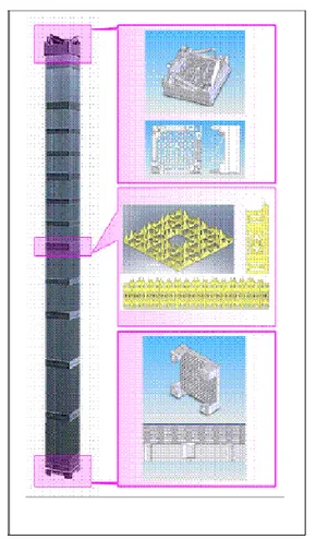
Figure 3.4.2. Typical 17x17 Fuel Assembly Figure 3.4.3. Primary water flow inside the core
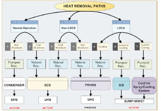
Other important design features in SMART are the simplified and improved safety systems. Passive safety systems such as passive residual heat removal system (PRHRS) are installed. These systems prevent and/or mitigate the effects of accidents such as over-pressurization and excessive heating of the primary system carrying away the core decay heat during an accident without the use of pumps, but only through natural circulation.
In detail, these are the main safety systems in the SMART reactor: • Reactor shutdown system (RSS):
The RSS starts a reliable and rapid shutdown if it spots a deviation out of the permitted range of monitored variable. This systems is made of control rods and their drive mechanism (CRDM). The shutdown signal makes the control rods drop into the reactor core by the use of only gravity force and consequently stops the neutron chain reactions
• Safety injection system (SIS):
The SIS is acts to prevent core damage when a small break LOCA occurs. So its function is to cover the core with a large quantity of primary water. If the pressure drops below 10 MPa the SIS is actuated automatically and injection of water into the reactor coolant system from IRWST starts immediately.
Rapporto “World status of the SMR projects”
LP1.B4 - 24 - CERSE-POLIMI RL-1351/2011
SIS is made of four independent trains: each train has a 100% capacity. The aim of that system is to provide vessel refilling so that the decay heat removal system can work properly also in a long-term scenario following an accident.
• Passive Residual Heat Removal System (PRHRS)
In case of an emergency such as a station black out, the PRHRS removes the core decay heat using natural circulation. Alternatively, PRHRS can be used if a long-term cooling is needed, for example in case of repair or refueling.
The PRHRS is designed with four independent trains with a 50% capacity each. Each train is made of one emergency cool-down tank (containing the water needed for cooling), a heat exchanger and a makeup tank.
A system made this way is able to maintain the core un-damaged for 36 hours without any other external actions by operators. In the case of a standard shutdown, so not in case of emergency, the residual heat is removed through the steam generators setting up a turbine bypass system.
• Shutdown Cooling System (SCS)
The SCS is used in together with the PRHRS to decrease the temperature of the RCS after the shutdown, from the hot shutdown temperature to the refueling one.
Steam generator or PRHRS act during the initial phase of the cool-down process. After the reactor coolant temperature and pressure have been reduced, the SCS, using heat exchangers and pumps, operates from now on to reduce the temperature, finally reaching and maintaining the refueling one.
• Containment Spray System (CSS)
CSS purpose is to reduce containment pressure and temperature due to a main steam line break (MSLB) or LOCA and to clear containment atmosphere from fission products. The CSS uses the in-containment refueling water storage tank (IRWST) and has two independent trains. The CSS provides orated water to the containment atmosphere by the use of sprayers from the upper containment parts.
• Reactor Overpressure Protection System (ROPS)
ROPS function is to reduce the pressure inside the reactor considering design basis accidents. The system is made of two pressurizer safety valves (PSVs), located in the upper part of the reactor. The piping discharging steam of PSVs are linked to the containment atmosphere through the reactor drain tank (RDT). In case primary system pressure increases over the limit, PSVs are opened and the steam is discharged into the RDT.
• Severe Accident Mitigation System (SAMS)
SAMS prevents the molten corium possibly resulting from a severe accident to go out of the containment. Characteristics of the design of cavity and containment and the safety systems together can prevent egress of corium can be avoided due to. In case of a severe accident water from CSS fills the small air gap under the RPV. External cooling is granted by the water in the IRWST preventing an egress of the corium out of the RPV. To prevent hydrogen explosion the containment has some hydrogen.
Rapporto “World status of the SMR projects”
LP1.B4 - 25 - CERSE-POLIMI RL-1351/2011
Figure 3.4.4 Security systems in SMART reactor
A thermal margin of about 15% , accommodating any transient regarding heat flux, is ensured by the low power density design with slightly enriched (<5 w/o) UO2-fueled core. This feature ensures the core thermal reliability under normal operation.
Soluble boron and control rods are the systems used to control reactivity during normal operation. To obtain a radial flat neutron flux burnable poison rods are introduced; this results in the increased thermal margin of the core. Constant average coolant temperature program is adopted in SMART reactors to improve load follow operation performance having stable pressure and water level within the pressurizer.
8 modular type once-through steam generator are designed as helically coiled heat transfer tubes and produce superheated steam at 30 degrees in normal operating conditions.
Among other improved design features is it possible to find the canned motor reactor coolant pump, that has no pump seals, preventing loss of coolant in case of a seal may suffer a failure. System reliability is also enhanced by four channel control rod position indicators.
Rapporto “World status of the SMR projects”
LP1.B4 - 26 - CERSE-POLIMI RL-1351/2011
2.5 KLT-40 (PWR-Loop, Barge)
Figure 3.5.1 KLT-40 schematic view of the reactor
KLT-40
Type PWR Power 150MWt 35/19.4MWe
Weight 21500 ton
Fuel Assembly 121
Vessel Base Material Steel, 15Cr2NiMo, VA-A Primary Pressure 12.7MPa
Rapporto “World status of the SMR projects”
LP1.B4 - 27 - CERSE-POLIMI RL-1351/2011
KLT-40 Core inlet temp. 280 °C Steam Output 240t/h Superheated Steam Pressure 3.72MPa Superheated Steam Temperature at SG Outlet 290°C Feedwater Temperature 170°C
Tube Material Titanium Alloy SG Weight 23 tons
Refueling 3.5 years
Figure 3.5.2 Primary circuit layout
The KLT-40S is a variant of the KLT-40 used to power icebreakers and it is used in the Russian floating nuclear power station.
Rapporto “World status of the SMR projects”
LP1.B4 - 28 - CERSE-POLIMI RL-1351/2011
Floating nuclear power stations are projected by Rosatom self-contained and with low-capacity. The stations are to be mass-built in factories or naval-building facilities and then moved to the destination point in coastal waters near a city, a town or an industrial enterprise. By 2015, at least seven of the vessels are supposed to be built.
This kind of systems are non-self-propelled vessels with a length of 144.4 metres (474 ft), width of 30 metres (98 ft), height of 10 metres (33 ft), and draught of 5.6 metres (18 ft). The vessel has a displacement of 21,500 tonnes and a crew of 69 people.
Figure 3.5.3 Floating plant layout
The core contains uranium dioxide fuel rods with high corrosion resistance cladding made of zirconium alloy; uranium fraction is also increased used a closely packed pattern, providing an high density of fuel compared to the volume core available.
Each reactor has its own containment that is a physical barrier projected to limit the spread of radioactivity and to localize fission products in case of a loss of coolant accident (LOCA), using emergency containment cooling systems.
Some features provide self-defense in the KLT-40: negative reactivity coefficients (fuel and coolant temperature, coolant specific volume, steam density and integral power); high heat capacity of the primary coolant and metal structures (safety margin provided by the design for the depressurization pressure of the primary system under emergency); limited outflow rate in case of a break, due to restriction devices in connection nozzles; once-through steam generators, limiting the rate of heat removal via the secondary circuit during steam line break accident.
Two KLT-40 naval propulsion reactors (modified) together provide up to 70 MW of electricity or 300 MW of heat, enough for a city with a population of 200,000 people. It can also be used for desalination plant producing 240,000 cubic meters of fresh water a day.
It must be pointed that floating plants could be more vulnerable to accidents and terrorism than land-based stations, considering also a history of naval and nuclear accidents in Russia and the former Soviet Union, including the Chernobyl disaster of 1986.
The 2011 Japanese nuclear accidents due provide a sharp contrast to some comparative safety advantages of floating nuclear plants. Land based nuclear facilities are designed to resist to severe ground accelerations. Sea water is needed for cooling, so nuclear power plant usually are located on the coast. Coastal locations tend to be the areas of maximum tsunami damage, requiring protective design against this phenomena.
Rapporto “World status of the SMR projects”
LP1.B4 - 29 - CERSE-POLIMI RL-1351/2011
A floating facility, near a coast but not in shallow water, can avoid the worst problems of earthquakes and tsunamis. In the event of an accident, terrorist attack, or other calamity, it is essential to keep the core cooled, usually by covering it with water. An emergency measure can be to lower the core into the sea. Finally, standard nuclear power plants’ decommissioning can be difficult and expensive.
Safety of the KLT-40 reactor is based on the defense-in-depth principle. This principle set up accident prevention and mitigation procedure and strategies, such as a number of physical barriers preventing diffusion of radiation and radioactive materials into the environment, and a system of technical and organizational procedures to protect barriers and retain their effectiveness, as well as protection of the personnel, population and environment.
There are lots of defense levels of technical and organizational measures under the defense-in-depth principle: prevention of abnormal operation and failure (based on negative reactivity coefficients and high thermal conductivity of the fuel); control of abnormal operation and detection of failure (active systems of control); control of accidents within the design basis (emergency protection rods, passive emergency heat removal system and self-actuating devices in emergency during shutdown); control of severe plant conditions (passive reactor vessel bottom cooling system and passive containment cooling system); mitigation of radiological consequences of significant release of radioactive materials (mainly organizational measures).
At present, fabrication of main equipment for the KLT-40 reactor and turbine-generator sets is near completion.
Rapporto “World status of the SMR projects”
LP1.B4 - 30 - CERSE-POLIMI RL-1351/2011
2.6 PHWR-220
Figure 3.6.1 Schematic plant layout PHWR-220
Power 754MWt 211MWe Active Core Dimensions 4.51m D x 4.95m H
Shell Dimensions 6m D x 5m; 25mm Thickness Design
Pressure/Temperature
.23 MPa/100 °C
Shell Weight 21.3 tons
Efficiency 26.5% Primary/Secondary
Coolant
High/Light Water
Core Damage Frequency 10^-5 Fuel Rods Diameter 15.22 mm Primary Coolant Flow
Rate
Rapporto “World status of the SMR projects”
LP1.B4 - 31 - CERSE-POLIMI RL-1351/2011
PHWR-220 Core outlet temp. 293 °C Core inlet temp. 249 °C Steam Output 2216 kg/s Steam Pressure 4.03 MPa Steam Temperature at SG
Outlet
250°C
Feedwater Temperature 171°C Refueling 2 years Plant life 40 years
Different size of water reactors are included in the Indian Pressurized Heavy Water Reactors consists of unists of 220 MWe, 540 MWe and 700 MWe.
Natural uranium dioxide and heavy water reactor are used in the PHWR-220. The reactor is made of a calandria filled with water and an integral assembly of two end shields. Pressure tubes containing the fuel are made of 306 Zr-2.5%Nb, in a square pattern design of 22.86 cm pitch. At the ending parts of pressure tubes it is possible to find a sort of cap made of AISI 403 modified stainless steel going through the shields and extending into the fueling machinary to facilitate power fueling. The calandria is a horizontal vessel containing the coolant channel, moderator, reactivity control mechanisms. Diameter and length of the main outer shell are 6.05 and 4.16 m. Calandria stands atmospheric pressure, so wall thickness is only 25 mm and made of austenitic stainless steel type 304 L.
Shield is very important, above all, during refueling process providing shielding to limit the dose rate in the fuelling machine vault, protecting the operator. They also have a support function for the fuel channels. A baffle palate separates the space inside the end shield into two. Water fills the front compartment and the rear one is full of carbon steel balls and water.
On-line refueling is an important feature of Indian PHWRs. Pressure tubes must be opened and resealed during reactor operation and the refueling machine must stand the high temperature and high pressure of the primary. A key spot in this process in the fuel handling system. It’s composed by two fuelling machines working in unison During refueling operation , fueling machines are connected on the upstream end and on the downstream side of the pressure tube that needs refueling. In this way the upstream machine loads the new fuel and the downstream one receives the spent fuel assemblies.
The primary heat transport circuit has four coolant pumps with three mechanical seals that, singularly, can sand full system pressure, providing good boundary sealing.
Rapporto “World status of the SMR projects”
LP1.B4 - 32 - CERSE-POLIMI RL-1351/2011
Figure 3.6.2 Schematic of the primary heat transport system PHWR
PHWR-220 is designed with 4 recirculation steam generators, vertical mushroom type, with U-tubes in which flows the primary coolant. Steam generators are located in two concrete zones, on the opposite sides of the reactor. Hot water if the primary circuit flows from the reactor to the inlet of the steam generator; the feedwater flows back to the SG inlet at 171°C. Steam separator are placed in the upper part of the steam generator to separate water from dry steam.
Indian PHWR’s design is projected to reach fundamental safety objectives according to regulatory requirements and standards. Key spots for safety design are the following: defense in depth, physical and functional separation of systems relevant for safety, detailed safety analysis using both deterministic and probabilistic methods, redundancy of safety systems, routine testing.
Secondary containment surrounds the primary one and it’s made of pre-stressed, while the primary one is built using reinforced concrete. The gap between inner and outer containment is maintained at a negative pressure to minimize the possibility of a possible release to the environment during accident conditions. In case of accidents all lines opening to the containment atmosphere are automatically closed; this process is triggered by pressure sensor or activity growth inside the containment. The containment is provided with some systems designed to start after an accident in order to cool down the containment atmosphere, limiting the maximum pressure and to maintain a clear atmosphere inside the containment.
There’s the possibility to increase fuel burn up beyond 15000 MWd/TeU using higher fissile content materials like enriched uranium, instead of natural one, MOX or TOX fuel. This enhancement is under investigation. Actually the maximum burn up that has been studied is 30000 MWd/TeU.
Rapporto “World status of the SMR projects”
LP1.B4 - 33 - CERSE-POLIMI RL-1351/2011
Slightly Enriched Uranium Bundles (SEU), MOX and thorium dioxide bundles and deplete uranium bundles were designed, and successfully irradiated in different PHWR-220. In order to flatten the flux thorium bundles and reprocessed depleted uranium dioxide bundles were in the initial fuel load Then MOX-7 fuel evolved in a 19-element cluster, with inner seven elements made of MOX pellets and outer 12 elements consisting only in natural uranium dioxide pellets.
The SEU bundle design differs from the previous one, in fact it’s composed by a 19-element fuel bundle with a 0.9% enrichment.
Rapporto “World status of the SMR projects”
LP1.B4 - 34 - CERSE-POLIMI RL-1351/2011
2.7 VBER-300 (PWR-loop)
Figure 3.7.1 VBER-300 Plant layout
VBER-300 Power Core Size Core Weight Coolant Coolant temperature 917MWt 335MWe 2.29m D x3.53m H 20.5cm thickness 306.6 tons (1300 working) Light Water 400-503°C Core Damage Frequency <10^-6
Operating Pressure 16.3 MPa Coolant flow rate 4483kg/s Inlet/Outlet Core
Temperature
Rapporto “World status of the SMR projects”
LP1.B4 - 35 - CERSE-POLIMI RL-1351/2011
VBER-300 Steam Flow Rate 472 kg/s Steam Pressure 4.37 MPa Inlet/Outlet SG Temperature 220-305°C Fuel UO2 Enrichment 4.95% U-235 Refueling 72 months Structural Material HT-9 ferritic martensitic steel Efficiency 33%
Plant Design Life 60 years
The VBER-300 reactor is designed to be a power source, ground-based, and nuclear also a cogeneration plant, using its thermal power for desalination purpose. So, considering reactor design and layouts, the most suitable applications are: electrical power generation, seawater desalination and cogeneration of electricity and heat for district heating.
As most of Russian SMRs the VBER-300 RP is the result of the evolution of naval propulsion reactors. Increasing mass increases the thermal power output but the reactor plant layout and main design solutions are kept as similar as possible to those of marine propulsion reactors. The final design is the result of matching knowledge from naval systems and from that granted by the experience on VVER-type reactors operation and successes in the field of nuclear power plant safety.
The vessel consists of a reactor vessel and four steam generators and associated main coolant pumps connected to the reactor vessel by coaxial nozzles. The reactor vessel has a cylindrical body with an elliptical bottom. The modular design reduces reactor unit mass and volume, so that the specific capital investments decrease, and safety is enhanced by the exclusion of main circulation pipelines and possibly associated large and medium break LOCAs.
In the VBER-300 light water acts both as primary coolant and moderator. The hot primary water flows in a once-through steam generator that produces slightly superheated steam and sending it to the turbine it is possible to produce up to 335MWe of power. It is also possible to take off a small amount of steam to heat up the district heating circuit fluid.
Steam generator results in a modular coil-type vertical heat exchanger. Primary water lows inside the tubes, and the secondary outside. The tubes modules are grouped on the feedwater and steam sides into three independent sections.
Main coolant pump consists of an axial flow pump moved by canned electric motor constituting. Other systems enhance pumping efficiency, such as a guide flange, an axial-type console impeller and a guide vane. Guide flange and vane shape the flow at the impeller inlet and push the coolant in the pressure chamber.
In the VBER-300 project reliability and safety of the reactor play an central role, as well as high economic indicators of the fuel cycle that lead to the cassette design of the reactor core, as successfully applied previously in operation of VVER reactors.
Rapporto “World status of the SMR projects”
LP1.B4 - 36 - CERSE-POLIMI RL-1351/2011
Pellets 7.6 mm in diameter are used as fuel. Uranium enrichment is up to 5% (maximum licensed enrichment).
Shroudless fuel assemblies (FA) are used in VBER-300 as in VVER-1000 where they have proved a high load-carrying capacity and high resistance to deformation.
VBER-300 fuel is handled and transported as follows: spent FAs moved from the reactor into the storage pool and then into special container to be transported; to reload the fuel and in-vessel equipment it is used the dry method; a protective tube houses the reloaded FA; a shielded transportation container grants biological protection for the servicing personnel during dry materials transportation.
Figure 3.7.2. General view of the VBER-300
Transportation container is moved by the reactor compartment crane thanks to a double lift system. The fresh fuel storage provides acceptance and storage of fresh fuel, and space for fuel preparation, before it is inserted into the core.
A special railway transportation is set up to deliver fresh fuel to the site, that can accommodate a 20% fuel in excess compared to the quantity needed to load the core. The fresh fuel storage and the reactor compartment are connected with an internal railway.
Dismounting the control rod drive mechanism is necessary before refueling process can begin; once the reactor cover is opened, the top structure is removed.
Rapporto “World status of the SMR projects”
LP1.B4 - 37 - CERSE-POLIMI RL-1351/2011
Figure 3.7.3. Steam generating module (1 ・ tubing, 2 ・ steam generating module)
Refueling is made by the fuel handling machine handling, moving one FA at a time. The fuel handling machine is composed by a refueling tube housing one FA with the coolant (in this way it provides the biological shielding and heat removal).
Refueling process starts unloading spent FA from the reactor, transporting them to the decay storage pool and putting them onto an assigned storage rack shelf. After this is done, the fuel handling machine loads one fresh FA into the reactor and installs it into the assigned core cell. One of the most important side aspects of the refueling process is that in that period of time it is possible to inspect the integrity of fuel elements cladding and of the core itself.
The decay storage pool houses spent fuel for about six years and can accommodate the entire core inventory.
A nuclear power plant must provide personnel and population protection against the consequences of the design basis and severe accidents, so a containment system has been studied. These are the basic features and systems of the VBR-300 containment solution: fuel retention system in the reactor vessel during accidents with severe core damage; passive heat removal system limiting containment pressure in LOCAs; separation of functions granting protection against internal emergency impacts and external impacts both natural or human-caused; iodine and aerosol air
Rapporto “World status of the SMR projects”
LP1.B4 - 38 - CERSE-POLIMI RL-1351/2011
purification system in order to clean air from radioactive leaks during accidents with containment standing a situation of overpressure.
In case of a ground-based nuclear cogeneration plant the containment structure is double, made of of an internal steel shell and an outer concrete shell (non pre-loaded).
The cylindrical steel shell dimensions are 28.0 m in diameter and 34 m high. The concrete shell is made of concrete with external diameter of 34 mm and height of 42.2 m.
Rapporto “World status of the SMR projects”
LP1.B4 - 39 - CERSE-POLIMI RL-1351/2011
2.8 ENHS (LMFBR- PbBi cooled)
Figure 3.8.1. Schematic representation of the ENHS reactor. ENHS Power Core Size Coolant Coolant temperature 125-180MWt 50-75MWe 3.64m x10m 5cm thickness PbBi 400-503°C Coolant flow rate 8320kg/s
Inner/Outer Eff Radius 16.41/111.83cm Fuel Rod Clad Diam 1.56cm
Rapporto “World status of the SMR projects”
LP1.B4 - 40 - CERSE-POLIMI RL-1351/2011
ENHS
Fuel Stainless Clad U-Pu Enrichment 12-13% Pu
Refueling 20 years
Structural Material HT-9 ferritic martensitic steel Efficiency 38.4-40.7%
The ENHS (Encapsulated Nuclear Heat Source) is based on the lead‐bismuth technology developed for Russian most advanced nuclear submarines. The ENHS is factory produced and it’s delivered fueled and sealed. It has to be installed in a reactor pool and it’s able to provide energy for about 22 Equivalent Full Power Years without refueling. At the end of the core life it would be substituted with a replacement “battery" and transported to a center for fuel cycle services. It may be an option for developing countries as well as for industrial countries. This reactor concept was studied by Ehud Greenspan and David Wade, its feasibility has been studied during 1999 through 2002 with the support of the DOE NERI program.
This DOE NERI sponsored project consisted of researchers from four institutions: The University of California at Berkeley (the lead organization), Lawrence Livermore National Laboratory, Argonne National Laboratory and Westinghouse. Three Korean organizations joined the project at the beginning of the second year; they are Korea Atomic Energy Research Institute (KAERI), Korea Advanced Institute for Science and Technology (KAIST) and Seoul National University. The Korean organizations were supported by the Nuclear Energy Research Initiative program of the Korean Ministry of Science and Technology (MOST).
Throughout the project there was useful interaction with CRIEPI, and to a lesser extent, TOSHIBA researchers that were involved in the design of the 4S reactor. In the second part of the project CRIEPI undertook to perform an independent evaluation of the transient behavior and safety characteristics of the ENHS reactor.
Most of the research done for this project and the obtained results are described in more than 40 publications that are openly available. University of Bologna has been involved in some final analysis of the ENHS core design in the years 2005‐2009.
Designers working on that project focus their attention on some characteristics: natural circulation cooling, 20 full power years with no refueling, simplicity in construction operation and maintenance, transportability, autonomous load following capability. Using small steam generators allows the plant to operate with supercritical steam increasing efficiencies up to about 40%. There are no particular decay heat removing systems other than a reactor air cooling system to maintain the vessel at an appropriate temperature. One of the most important feature is the possibility to ship the core “ready to use” and sealed. This is possible thanks to the absence of mechanical connection between reactor and secondary system. This sealed core is another barrier against proliferation. In fact transportation can be easier as the module with solid metal stored in the primary system can be used as shipping cask.
Rapporto “World status of the SMR projects”
LP1.B4 - 41 - CERSE-POLIMI RL-1351/2011
Except for control and safety (7 pieces total) there are no moving components; there are no fuel assemblies as every element is tied up to the grid plate.
ENHS reactor is designed to serve developing countries or to be placed in areas difficult to reach. It can be used to provide electricity, desalinization or district heating.
There’s also the possibility of a different layout using heat pipes. This way lead temperature can be risen to 1040K and the entire module can be reduced in size. This design enhance passive heat removal and mechanical resistance of the core.
Factory fabrication and fuelling of the module makes construction time extremely short, about 2 years; this has a great influence also upon economical aspects.
The basic features of the original reactor concept did not change during the years, but the ENHS module is made more robust and more practical to fabricate. It is designed to have natural circulation of both the primary and secondary coolants. The variant design that uses cover‐gas lift‐pumps for both the primary and the secondary coolants will not be analyzed here. Figure 3.8.2. Schematic representation of the ENHS core The ENHS core, Figure 2, is an annular cylinder made of uniform lattice of fuel rods that are individually tied‐up to the lower grid plate; there are no fuel assemblies. There is are no blanket and no solid reflector assemblies. The core would be supported vertically from the bottom by the lower grid spacer plate. The pins would be held down against upward hydraulic flow and buoyancy forces by tying each pin to its pedestal on the lower grid plate in a way that allows for 2π steradian degree of freedom. The pins float in the coolant like an array of buoys, but are pinned in position at the bottom, and are positioned radially and azimuthally near the mid elevation by the upper grid spacer. The bottom pinning is done in a redundant fashion so
Rapporto “World status of the SMR projects”
LP1.B4 - 42 - CERSE-POLIMI RL-1351/2011
that a single failure will not release a pin. The use of pin pedestals allows to eliminate a bottom grid spacer and to thereby avoid its pressure drop, this is an important consideration for the natural circulation cooling. The coolant enters the lower plenum from the downcomer via large holes in the sides of the core barrel. Then it distributes itself across the core radius, flowing radially between the pedestals, and turns and flows upward through the macro pin lattice. The large coolant gaps of the lattice and the pedestal placement facilitate the radial distribution both in the plenum and throughout the pin lattice.
The Control and Shutdown Systems consist of a single neutron absorber assembly located centrally in the core also referred to as the “Central Safety Assembly” and six segments of an annulus that surrounds the core sometimes referred to as the “peripheral absorbers”. The former is located in the coolant‐filled cavity at the core center; the diameter of this cavity is determined so that the reactivity worth of the safety element will be adequate. The central cavity can also be used for flattening of the radial power distribution across the core. The central absorber has an electromagnetic latch that does not engage until the start‐up temperature of 400◦C is achieved. At this temperature the assembly can be withdrawn. Normal operational shutdowns can be accomplished with the peripheral absorbers. The reactor is brought critical by a hydraulic system that moves the peripheral absorbers up at 1 mm/s to compensate for the negative temperature coefficient of reactivity. At the full power position, the peripheral absorber segments are stopped from further upward movement by mechanical stoppers whose movement is established by high‐reliability gear drives. The height of the peripheral absorbers will be adjusted once a year or two to compensate for a slight drift in reactivity due to fuel burn‐up. During shipping and reactor installation the absorbing elements are securely latched in place. The active element for both central and peripheral absorbers is B4C and tungsten; being heavier than LBE tungsten can scram by gravity.
The ENHS module, Figure 1, is designed to be as simple, robust and prolifera‐ tion resistant as possible. There are no moving components except for the control and safety elements drives. This module will be manufactured and fuelled in the factory and shipped to the site as a weld‐ sealed unit with solidified LBE filling the vessel up to above the fuel rods. A unique feature of LBE, that makes it possible to embed the fuel rods and core structure in solid LBE without damage, is its nearly zero coefficient of volumetric expansion upon phase change. At the end of its core life the module will be removed from the reactor pool and it will be stored on site until the decay heat drops to a level that will permit to solidify the coolant and to convert the module into a shipping cask. A schematic description of the design concept of the ENHS reactor is depicted in Figure 1. The nuclear steam supply system (NSSS) consists of one ENHS module and eight small steam generators. There is no mechanical connection between the module and the steam generators. Both primary and secondary coolants flow by natural circulation. The primary coolant that is heated in the core flows up the riser, turns over into the Intermediate Heat Exchanger (IHX) and flows back into the coolant plenum underneath the core. In a vertical counterflow arrangement the secondary coolant flows from the pool outside of the vessel into the bottom of the IHX and exits back to the pool near the top of the IHX. The IHX consists of rectangular channels that are connected at their top and bottom to a tube sheet. The 4 mm thick rectangular channel walls provide the barrier between the primary and the secondary coolants whereas the inner and outer walls provide the structural support. More conventional IHX made of circular tubes could be used as well. Relative to circular tube IHX the rectangular channel IHX features close to an order of magnitude smaller number of channels and smaller friction losses due to elimination of the grid spacers.