Analysis of Virtual Network
Functions for 5G networks through a
Fault Injection Approach
Politecnico di Milano
Dipartimento di Elettronica, Informazione e Bioingegneria
Candidato: VALERIO FERRETTI, 853651
Thesis Advisor: Elisabetta Di Nitto
Thesis Co-advisor: Bin Xiang
Ringraziamenti
Ringrazio la professoressa Elisabetta Di Nitto per avermi dato la possi-bilità di svolgere questo lavoro di tesi e per avermi seguito in tutte le fasi di ricerca e di stesura. Ringrazio Bin Xiang per avermi aiutato e consigliato durante l’intero periodo di lavoro. Un ringraziamento spe-ciale alla mia famiglia, per avermi sopportato incondizionatamente du-rante gli anni di studio. Ed infine, un ringraziamento a Mercedes del Fresno Navarro, per essermi stata sempre accanto durante tutto il mio percorso universitario, per aver condiviso con me i momenti migliori e per avermi aiutato e sostenuto nei momenti più difficili.
Abstract
The fifth generation (5G) mobile network is on its way to change the future connectivity. Rather than an evolution, 5G networks will be a revolution in the telecommunication world, due to the increasingly high number of requirements and challenges that the next generation mobile network must address. Ultra high speed radio access, greatly enhanced responsiveness and reliability, massive number of new con-nected IoT devices with very different network requirements, are only some the challenges that future networks need to face. The next gen-eration mobile network relies on a number of technologies to achieve such an accomplishment. Virtualization is, rightfully, considered a an enabling technology for the 5G vision as it allows to properly meet many of new, challenging 5G requirements. Instead of leveraging proprietary, monolithic hardware appliances, network functions, that power up to-day telecommunication, will be software implemented and run on top of commodity hardware inside virtual machines. They will be managed by an orchestrator, which will chain them together to form more complex virtual network services (VNS). A lot of effort is already being spent on the virtualization of core mobile network components like the Evolved Packet Core. Virtualization will enable scalability, flexibility when it comes to provide new network services, a significant cost reduction and it will enable network slicing to better be able to meet the greatly vary-ing network requirements that IoT devices expose. This thesis work is focused on analyzing virtual network services (VNS) through a fault injection based approach, which can be defined as the process of stress-ing and injectstress-ing faults to components of a VM, hoststress-ing a virtual net-work function (VNF), and even limiting or disabling some of its func-tionalities in order to test its functioning under challenging conditions,
that mimic real world high pressure scenarios. The Fault Injection Ap-proach allows us to draw conclusions and spot weaknesses of virtual network functions (VNF) in order to provide reports to developers. It also allows us to evaluate how well the orchestrator and the underly-ing platform are able to scale VNFs, to manage their faults, to restore their state before failure. Fault Injection is carried through a fault in-jection tool, developed on purpose using the java language. Such a tool connects through SSH to VMs hosting a VNF and inject a number of dif-ferent faults to test their behaviour under challenging conditions. Tests will be run on two different VNSs: Iperf-VNS and the SIP-VNS.
Estratto
La quinta generazione delle reti mobili è destinata a cambiare drastica-mente la connettività del futuro. Più che un’evoluzione, le nuove reti 5G saranno una rivoluzione nel mondo delle telecomunicazioni, a causa del crescente numero di requisiti e sfide che la prossima generazione di reti mobile dovrà affrontare. Una nuova, superveloce rete wireless di ac-cesso, grandi miglioramenti dell’affidabilità e della latenza, un enorme numero di nuovi dispositivi e sensori con requisiti di rete molto diversi fra loro, sono solo alcune delle sfide che le nuove reti 5G dovranno affrontare nei prossimi anni. Il raggiungimento degli obiettivi fissati sarà possibile grazie all’utilizzo e allo sfruttamento di un gran numero di tecnologie, siano esse evoluzioni di soluzioni tecniche già esistenti o nuove introduzioni nel mondo delle telecomunicazioni. La virtualiz-zazione è, giustamente, considerata una tecnologia chiave per le reti di nuova generazione, in quanto facilita l’adempimento di diversi requisiti fondamentali delle reti 5G. Invece di utilizzare hardware proprietario e monolitico, le funzioni di rete saranno implementate in software ese-guite come macchine virtuali su server general purpose. Un orchestra-tor si occuperà della gestione di ogni singola funzione di rete virtuale (Virtual Network Function, VNF), e le connetterà tra loro per formare più complessi servizi di rete virtuali (Virtual Network Services, VNS). Molto lavoro è già stato dedicato alla virtualizzazione di alcuni com-ponenti fondamentali delle reti mobili come Evolved Packet Core. Tra i vantaggi portati dalla tecnologia di virtualizzazione i più importanti nell’ottica 5G sono sicuramente la scalabilità dei VNSs, una significa-tiva riduzione dei costi, grande flessibilità nell’offrire all’utente nuovi servizi di rete. Il lavoro di tesi in questione si focalizza sull’analisi di VNSs e VNFs tramite un approccio basato sul concetto di fault
injec-tion. Tale approccio può essere definito come il processo tramite cui si stressano vari componenti di una macchine virtuale che ospita una VNF, o si generano artificialmente delle condizioni di errore all’interno della stessa, con l’obiettivo di testarne il comportamento e il funzionamento in condizioni simili a quelle in cui si troverebbe nel mondo reale quando sottoposta a grandi volumi di traffico. L’analisi tramite fault injection consente di ottenere un duplice vantaggio. Da la possibilità di valutare le vulnerabilità e le debolezze dell’implementazione di una VNF e, allo stesso tempo, da la possibilità di valutare quanto efficacemente la pi-attaforma software di gestione dei VNSs è in grado di scalarli, di rea-gire a condizioni di errore che essi generano, di ripristinare il loro stato prima del verificarsi di un errore. In questo lavoro di tesi, l’analisi basata su fault injection è stata condotta tramite un fault injection tool (FIT) scritto nel linguaggio Java. Il FIT si connette tramite il proto-collo SSH alle macchine virtuali che ospitano VNFs, genera diverse condizioni di stress ed errori per poi poter analizzare il comportamento delle stesse e il comportamento complessivo di tutto il VNS. Test di questo tipo sono stati eseguiti su servizi di rete virtuali quali Iperf-VNS e SIP-VNS.
Contents
List of Figures IV
List of Abbreviations VI
1 Introduction 1
1.1 The 5G Vision: Use Cases . . . 2
1.2 The 5G Vision: Requirements . . . 4
1.3 5G Enabling Technologies . . . 7
1.4 Thesis Contribution . . . 9
1.5 Document’s Structure . . . 10
2 State Of The Art 13 2.1 The Mobile Operator Network . . . 13
2.2 The Evolved Packet Core . . . 15
2.3 The Radio Access Network . . . 17
2.4 The role of Virtualization . . . 18
2.5 Summary . . . 23
3 The ETSI Network Function Virtualization MANO Specifi-cation 25 3.1 Introduction to ETSI NFV MANO Specification . . . 26
3.1.1 Core Principles . . . 26
3.1.2 Architectural Framework Functional Blocks . . . 27
3.2 Core Functional Blocks . . . 30
3.2.1 The Network Function Virtualization Orchestrator . 30 3.2.2 The Virtualized Infrastructure Manager . . . 33
3.3 Other Functional Blocks . . . 38
3.4 Data Repositories . . . 39
3.5 Reference Points and Interfaces . . . 41
3.6 Summary . . . 43
4 ETSI NFV-MANO Implementation: Openbaton 45 4.1 Deployment Notes: Resource Utilization . . . 46
4.2 Openbaton Implementation of the ETSI NFV MANO Main Components . . . 47
4.3 Openbaton Services and Monitoring System . . . 54
4.4 Communication Inside the Openbaton: AMPQ and RESTful APIs . . . 62
4.5 VNS Onboarding and Deployment Process . . . 63
4.5.1 Virtual Network Service Onboarding Process . . . . 64
4.5.2 Virtual Network Function Deployment Process . . . 72
4.5.3 Virtual Network Function Lifecycle Stages . . . 75
4.6 Other Solutions for Network Function Virtualization: MCORD 76 4.7 Summary . . . 80
5 The Fault Injection Analysis 82 5.1 Introduction . . . 82
5.2 Fault Injection Analysis Applied to Network Function Vir-tualization . . . 84
5.3 The Fault Injection Tool . . . 87
5.4 The FIT Technical Requirements . . . 90
5.5 The FIT Testing Functionalities . . . 91
5.6 Summary . . . 96
6 Fault Injection Analysis on Iperf-VNS and SIP-VNS 98 6.1 Iperf-VNS and SIP-VNS . . . 98
6.2 Iperf-VNS Fault Injection Analysis . . . 103
6.3 SIP-VNS Fault Injection Analysis . . . 106
6.4 Summary . . . 110
7 Conclusion and Future Work 113
List of Figures
1.1 5G Enabling Technologies. . . 8
2.1 Mobile Network Architecture. . . 14
2.2 Evolved Packet Core. . . 15
2.3 Radio Access Network. . . 18
3.1 ETSI NFV MANO Functional Blocks. . . 29
3.2 ETSI NFV MANO NVFO. . . 31
3.3 ETSI NFV MANO VIM. . . 35
3.4 ETSI NFV MANO VNFM. . . 37
3.5 ETSI NFV MANO MinorComponenets. . . 38
3.6 ETSI NFV MANO DataRepositories. . . 40
3.7 ETSI NFV MANO Interfaces. . . 42
4.1 Openbaton Architecture Overview. . . 48
4.2 Openbaton NFVO. . . 49
4.3 Openbaton VIM. . . 51
4.4 Openbaton VNFM. . . 53
4.5 Openbaton Services and Monitoring System. . . 55
4.6 Openbaton Instanciation Process. . . 73
4.7 VNF_Lifecycle. . . 75
4.8 MCORD-EPC. . . 79
6.1 SIPp Message Flow. . . 102
6.2 Iperf Test Results. . . 104
List of Abbreviations
API: Application Program Interface AS: Access Stratum
ASE: Auto Scaling Engine CAPEX: CAPital EXpenditure CO: Central Office
EM: Element Management
EM: Element Management System EPC: Evolved Packet Core
E2E: End To End
ETSI: European Telecommunication Standard Institute FIA: Fault Injection Analysis
FIT: Fault Injection Tool
FMS: Fault Management System
FOCUS: Fraunhofer Institute for Open Communication Systems HSS: Home Subscriber Server
HTC: Human Type Communication IoT: Internet of Thing
IMSI: International Mobile Subscriber Identity IP: Internet Protocol
LTE: Long Term Evolution
MANO: MANagement and Orchestration MME: Mobile Management Unit
MNO: Mobile Network Operator MTC: Machine Type Communication NAS: Non Access Stratum
NF: Network Function
NFV: Network Function Virtualization
NFVI: Network Function Virtualization Infrastracture
NFVI-PoP: Network Function Virtualization Infrastracture Point of Presence NFVO: Network Function Virtualization Orchestrator
NGMN: Next Generation Mobile Network NGN: Next Generation Network
NS: Network Service
NSE: Network Slicing Engine OPEX: Operational EXpenditure OSS: Operation Support System
PCRF: Policy Control and Charging Rule Function PDN: Packet Data Network
P-Gateway: Packet Data Network Gateway PNF: Physical Network Function
QoS: Quality of Service RAN: Radio Access Network
SDN: Software Defined Networking S-Gateway: Serving Gateway
SLA: Service Level Agreement TU: Technische Universität UE: User Equipment
VDU: Virtual Deployment Unit
VIM: Virtualized Infrastructure Manager VLD: Virtual Link Descriptor
VLR: Virtual Link Record VM: Virtual Machine
VNF: Virtual Network Function
VNFC: Virtual Network Function Component VNFD: Virtual Network Function Descriptor VNFR: Virtual Network Function Record VNS: Virtual Network Service
VNSD: Virtual Network Service Descriptor VNSR: Virtual Network Service Record
VNFFG: Virtual Network Function Forwarding Graph
VNFFGD: Virtual Network Function Forwarding Graph Descriptor VNFFGR: Virtual Network Function Forwarding Graph Record VNFM: Virtual Network Function Manager
Chapter 1
Introduction
In 2014, the Next Generation Mobile Network (NGMN) alliance decided to focus their future activities on defining the end-to-end requirements for the fifth generation mobile network (5G). The latter is considered the evolution, or the next iteration, of 4G Long Term Evolution (LTE) mobile networks. A global team developed the NGMN 5G White Paper [2] (published in March 2015) which delivered consolidated operator requirements that would support the standardization and development of 5G. The 5G network will enable significantly greater mobile speeds and real-time connectivity for mission-critical and potentially life-saving devices and applications with ultra low latency requirements. 5G will also provide truly ubiquitous connectivity in the most challenging and remote areas of the world and will connect billions of Internet of Things (IoT) devices with a variety of speeds and data volume requirements. 5G is an ambitious goal and work on key technologies to enable it has already begun. In much the same way that 4G LTE was rolled out in 2008, but it achieved its objectives years later with 4G LTE Advanced standard, 5G will be a steady evolution that begins with commercial availability expected in 2020. A number of different technologies are essential for achieving 5G objectives. Some of them are already part of the 4G standard and will need to be evolved and improved, others will be introduced for the first time in the telecommunication world. The next three sections will respectively introduce 5G use cases, main requirements and enabling technologies.
1.1
The 5G Vision: Use Cases
The NGMN alliance has developed twenty five use cases for 5G, which have been gathered into eight different categories. Rather than a ex-haustive list of all possible scenarios, they are used as representative samples in order to extract the 5G requirements. The following list quickly summarizes the main NGMN use case families to show the im-portance of mobile connectivity in the fully connected, future society. More information about 5G Use Cases can be found in the NGMN 5G White Paper [2].
1. Broadband Access in Dense Areas: This category of use case includes all those scenarios where it is necessary to provide broad-band access to users in densely populated areas like centers of big city or multy-storey buildings. Communications are expected to be pervasive and part of everyday life. Augmented reality, multi-user interaction, three dimensional services will be among the ser-vices which play an increasingly significant role in the 2020+ time frame.
2. Broadband Access Everywhere: This family of use cases in-cludes all scenarios where it is necessary to grant connectivity in urban, suburban, rural and, in general, scarcely populated ar-eas. Though it is not possible to guarantee the same latencies and bandwidths, it is aim of 5G to provide a consistent user experi-ence.
3. Higher User Mobility: The fifth generation (5G) of mobile net-work will need to address a growing demand of connectivity in vehicles, train or even airplanes. Though some of scenarios are already supported by current networks, others, like connectivity in aircrafts, autonomous driving, safety and vehicle diagnostic, are new use cases which requires proper technological solutions. 4. Massive Internet Of Things: by 2020, Gartner [13] forecasts
that there will be around 20 billion connected devices in the In-ternet of Things (IoT). Scalability is an extremely important
re-quirement for the new 5G standard. The upcoming IoT era chal-lenges network operator not only because of the number of new connected devices but also and above all for their different charac-teristics. These devices will have widely varying network require-ments, from environmental sensors for agricultural applications installed in remote areas that might send a few bits of data every few days or weeks, to extremely high-precision, low-latency de-vices in nano-biotechnology, autonomous cars, and mission-critical industrial environments that rely on real-time communication for potentially lifesaving functions. 5G networks will need to handle this great variety of devices and network requirements appropri-ately.
5. Extreme Real-Time Communications: This family of gathered all scenarios where real time communication is crucial. This kind of use cases pose a widely varying set of requirements. They may extremely high throughputs, sub-millisecond latencies, high relia-bility or availarelia-bility.
6. Ultra-Reliable Communications: Specific classes of applica-tions that will leverage the 5G network will need extremely reli-able man to machine connections. Examples of such applications are automated traffic control and driving. These new technologies will mitigate the risk of road accident, improve the traffic effi-ciency and even support the mobility of emergency vehicles. Such scenarios may require low end to end latency or improved band-width to support vehicle to vehicle or vehicle to infrastructure communication.5G should provide also high reliability, availabil-ity and enhanced scalabilavailabil-ity in order to support these use cases. 7. Lifeline Communication: Current mobile networks have improved
public safety and emergency services. This trend will keep on in the following years: 5G will need to provide robust communica-tions even in case of natural disaster like tsunami, hurricanes or earthquakes supporting several types of communications, like in-stant messages, voice or localization signals. Efficient networking
and low power consumption of user devices are key factors in or-der to support such communications for several days.
8. Broadcast Like Services: This set of use cases includes all sce-narios in which efficient broadcast communication will be needed. These services may distribute content as done today (typically only downlink), but also provide a feedback channel (uplink) for interactive services or acknowledgement information. Both, real-time or non-real real-time services should be possible.
1.2
The 5G Vision: Requirements
The 5G requirements are derived out of NGMN’s vision of the poten-tial use cases and listed in the NGMN 5G White Paper document [2]. Anyway, such use cases demand very diverse and sometimes extreme requirements. It is anticipated that a single solution to satisfy all the extreme requirements at the same time may lead to over-specification and high costs. Nevertheless, several use case families are anticipated to be active concurrently in the same operator network, thus requiring a high degree of flexibility and scalability of the 5G network. Since each use case family poses different challenges in terms of requirements to be met, diverse sets of requirements are provided: one for each use case family. Of course, they are formulated in such a way that the most challenging use case in each category is satisfied. Additionally, a diverse set of requirements is specified for particular situations like extremely crowded areas or high speed mobility conditions (trains and airplanes). Specifying the requirements’ values set for each use case category is out of the scope of this text. I will, instead, mention require-ments that characterize extreme use cases as they properly highlight the technological challenges that 5G needs to face.
• User Experience Data Rates: Data rate requirements are ex-pressed in terms of user experienced data rate, measured in bit/s at the application layer. In the following I will include for sake of brevity only down link speeds. The required user experienced
data rate should be available in at least 95% of the locations (in-cluding at the cell-edge) for at least 95% of the time within the considered environment. Use case specific user experienced data rates up to 1 Gbps should be supported in some specific environ-ments, like indoor offices, while at least 50 Mbps shall be available everywhere. Though, the NGMN White Paper specifically mention 1 Gbps as the user experience maximum data rate, several more recent documents report speeds that raise up 10 Gbps or even 20 Gpbs.
• E2E Latency: The E2E latency measures the duration between the transmission of a small data packet from the application layer at the source node and the successful reception at the application layer at the destination node plus the equivalent time needed to carry the response back. The 5G system should be able to pro-vide 10 ms E2E latency for even not latency sensitive use cases and 1 ms E2E latency for the use cases which require extremely low latency. Note these latency targets assume the application layer processing time is negligible and that both source and tar-get nodes are located inside the 5G network.
• Mobility: Mobility refers to the system’s ability to provide seam-less service experience to users that are moving. In addition to mobile users, the identified 5G use cases show that 5G networks will have to support an increasingly large segment of static and nomadic users/devices. 5G solutions therefore should not assume mobility support for all devices and services but rather provide mobility on demand only to those devices and services that need it. In other words, mobility on-demand should be supported, rang-ing from very high mobility, such as high-speed trains/airplanes, to low mobility or stationary devices such as sensors or smart me-ters. For each use case the 5G White Paper specify a speed in-terval within which the use case requirements should be guaran-teed. Speed is measured as the relative speed between the user and the network edge, at which consistent user experience should be ensured. The mobility extreme cases are indoor or static de-vices end airplane connectivity. The former should be guaranteed
1Gbps bandwidth and 10ms latency, while airplane connectivity only guarantees 15Mbps speeds.
• Connection Density and Traffic Density: Connection Density and Traffic Density regard respectively the number of active con-nections per square kilometers and the amount of traffic exchanged by all devices per square kilometer over the 5G network. The first is measured as thousands of connections per square kilometer, the second one is the product between required user experience data rate and connection density. Since Traffic Density can be sim-ply calculated, I will report only extreme values for Connection Density metric. They range from few hundred connections per squared kilometers for broadband access in rural areas to several hundred thousands connections for broadband access in dense ar-eas. Such datas considered the presence of only one operator. • Availability: Availability is a probabilistic measure of the length
of time a system or network is functioning. 5G should enable 99.999% network availability, including robustness against climatic events and guaranteed services at low energy consumption for critical infrastructures (e.g., hospitals, network management). • Reliability: The reliability of a communication is characterized by
its reliability rate, defined as follows: the amount of sent packets successfully delivered to the destination within the time constraint required by the targeted service, divided by the total number of sent packets. Note that the reliability rate is evaluated only when the network is available. The reliability rate depends on the ser-vice and use case. The 5G technology should allow high reliability rates of 99.999%, or higher for the use cases that demand it, in particular those under the ultra-high reliability and ultra-low la-tency use cases category. For use cases for which reliability may be less an issue, e.g. some non-delay critical MTC use cases, the reliability rate may be 99% or even lower depending on the asso-ciated trade-off needs.
5G requirements. Refer to the NGMN 5G White Paper [2] for a much more in depth list of them.
1.3
5G Enabling Technologies
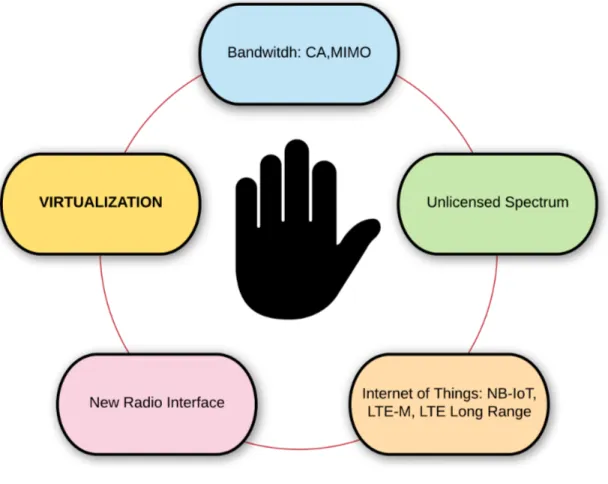
Once the 5G requirements are properly stated it becomes clear that 5G’s goals and objectives are ambitious and they will be reached along time through an evolutive process. This evolution relies on a number of different technologies that are considered real 5G enablers. Some of them have already been employed in the 4G standard and will need to be refined and improved. Others are new technologies that have never been used in the telecommunication world before. In this paragraph we list some of the most important ones which can be summarized in 5 big sets as shown by the Figure 1.1 in the following page:
1. Network bandwidth: speeds of up to 20 Gbps will be achieved using a combination of innovations such as Carrier Aggregation (CA), massive Multiple Input Multiple Output (MIMO).
2. Unlicensed spectrum: Mobile Network Operators (MNOs) are increasingly using unlicensed spectrum in the 2.4 and 5 Gigahertz (GHz) frequency bands. 5G networks will need to tap into the vast amount of spectrum available in these unlicensed bands to offload traffic in heavily congested areas and provide connectivity for bil-lions of IoT devices. Advancements in Wi-Fi, LTE in Unlicensed spectrum (LTE-U), among others, provide better quality and reg-ulated access to unlicensed spectrum.
3. Internet of Things (IoT): IoT devices pose a diverse set of re-quirements and challenges for 5G networks. It’s only fair that IoT should likewise pose a diverse set of solutions as well. Some of them are NarrowBand IoT (NB-IoT), LTE Category M1 (LTE-M) and Long Range (LoRa).
4. New Radio (NR): although the other 5G innovations introduced in this section all have strong starting points in LTE Advanced Pro,
Figure 1.1: 5G Enabling Technologies.
5G NR is a true 5G native technology that has yet to be standard-ized. 5G NR addresses the need for a new radio access technology that will enable access speeds up to 20 Gbps.
5. Virtualization: network functions virtualization (NFV) enables the massive scale and rapid elasticity that MNOs will require in their 5G networks. Virtualization enables a virtual evolved packet core (vEPC), centralized radio access network (C-RAN), mobile edge computing and network slicing.
Virtualization is one of the most important 5G enabling technology and it is where software engineering comes into play to shape the next
generation networks. Today’s telecom networks are primarily built us-ing specialized, often proprietary, equipments meanus-ing that, technol-ogy used is owned by specific corporations or companies. These types of equipments are typically monolithic in design; that is, they consist of hardware, software, and associated management systems that offer little or no flexibility at all. Virtualizing the mobile operator network means to get rid of proprietary hardware to run network functions on top of commodity servers inside virtual machines. These new, virtual-ized network functions are called Virtual Network Functions (VNF) and they are chained together by an Orchestrator to form Virtual Network Services (VNS). Such an approach brings into the telecommunication world the advantages offered by cloud technologies: scalability, flexi-bility and a significant cost reduction.
1.4
Thesis Contribution
This thesis work is focused on the application of virtualization to mo-bile networks and, in particular, to the analysis of the behavior of Vir-tual Network Services (VNSs) and VirVir-tual Network Functions (VNFs) when undergoing heavy workloads or when suffering faults injected on purpose to mimic real world scenarios. This kind of analysis, called Fault Injection Analysis, is particularly important because it allows to spot vulnerabilities and weaknesses in the implementation of virtual network functions whose failure in a real world scenario would be con-sidered catastrophic. It also allows to evaluate how effectively the Or-chestrator is able to deal with stressed or faulty VNFs: how efficiently it is able to scale them, to restore their state before a failure or to re-deploy unrecoverable VNFs or VNSs. In a nutshell, the Fault Injection Analysis allows to assess how much network functions and services ac-tually benefit of the advantages that virtualization should bring. The Fault Injection Analysis is carried out through a tool developed on pur-pose that SSH into VM hosting a VNF. It, then, run some Linux com-mand on the target VM to inject faults or emulate heavy workloads, in order to test and evaluate the subsequent VNF behavior. Throughout this thesis work I have used the Openbaton as Network Function
Vir-tualization (NFV) based platform to run VNFs and VNSs. I chose it as it is a close and faithful implementation of the European Telecommuni-cation Standard Institute (ETSI) NFV Management and Orchestration (MANO) specification, written to define a widely shared, free and ven-dor independent standard upon which build and implement NFV based networks. The VNSs I will deploy and test are the Iperf-VNS and SIP-VNS whose purpose and functioning will be detailed with great care in following chapters.
1.5
Document’s Structure
This first chapter was a brief introduction to 5G requirements and en-abling technologies. Though it is far from complete, it depicts the big-ger framework where this thesis work is located and it better details the focus of this work and the importance of Fault Injection Analysis in the upcoming process of network virtualization. The second chap-ter is about the state of the art of current mobile networks. It briefly details how mobile networks work, it lists their main drawbacks and it explains with more care what advantages virtualization will bring to mobile networks in order to meet some of the 5G requirements. The third chapter is focused on the ETSI NFV MANO (European Telecom-munication Standard Institute Network Function Virtualization Man-agement and Orchestration) specification which defines a standard for the implementation of VNF based platforms. The fourth chapter deals with the Openbaton framework. Openbaton is the NFV based platform I used to onboard, deploy, run and test VNFs and VNSs, as it is a close and faithful implementation of the ETSI NFV MANO specification. It will introduce to Openbaton implementation choices that are not man-dated by the ETSI standard and it will be focused on VNF onboarding and deployment process. The fifth chapter gives a more clear definition and details about the Fault Injection Approach and present the Fault In-jection Tool (FIT). The sixth chapter deals with the fault inIn-jection based analysis on the Iperf-VNS and SIP-VNS deployed on top of the Open-baton platform. It will list results of the analysis, main weaknesses of VNFs and VNSs and it will evaluate Openbaton capabilities when it
comes to manage faulty network functions. The last chapter summa-rizes the analysis carried out and it reports necessary future work and developments.
Chapter 2
State Of The Art
2.1
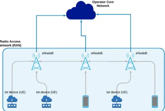
The Mobile Operator Network
A mobile network operator (MNO) is a provider of wireless telecommu-nications services that owns or controls all the elements necessary to sell and deliver services to end users like radio spectrum allocation, wireless network infrastructure, backhaul infrastructure and billing. From a high level point of view it is composed by the Radio Access Net-work (RAN) and the Evolved Packet Core (EPC). The first one connects wirelessly a User Equipment (UE) to an antenna, called evolved NodeB (eNodeB), which is the point of access for the user to the operator net-work. The EPC is a chain of network services running in a Central Office (CO) owned by the telecommunication provider that processes user traffic coming from eNodeBs. Each CO is a node in the operator network. Based on the service required by the user, traffic may be redi-rected from one CO to another or may be routed from the Mobile Op-erator Network (MNO) to the Packet Data Network (PDN) which is the IP network. User traffic is organized in bearers: IP packet flows typi-cally associated with a Quality of Service (QoS). Multiple bearers can be established for a user in order to provide different QoS streams or con-nectivity to different PDNs. For example, a user might be engaged in a VoIP (Voice over IP) call while at the same time performing web brows-ing or FTP download. A VoIP bearer would provide the necessary QoS for the voice call, while a best-effort bearer would be suitable for the
web browsing or FTP session. While the Radio Access Network may be undergo some changes in passage between 4G and 5G networks, EPC main blocks will not change dramatically from a functional point of view. Nonetheless EPC, and partially the RAN, will undergo an important and critical process of virtualization. The following brief description of RAN and EPC refers to the 4G standard, previous iteration of 5G as, from a functional point of view, their behavior will not change dramatically. Moreover, I am interested in specifying the high level role that RAN and EPC play inside the operator network, rather than their implemen-tation details. More information about Mobile Operator Network can found inside the Alcatel-Lucent White Paper "The LTE Network Archi-tecture" [3]. The Figure 2.1, in the following page, briefly summarizes the simplified Mobile Operator Network architecture described so far:
Figure 2.1: Mobile Network Architecture.
con-nectivity between user equipment (UE) and the packet data network (PDN), without any disruption to the end users’ applications during mo-bility. Additionally, the operator may provide also services to the end user that run inside its own network without the need of redirecting traffic to Packet Data Network (PDN).
In the next two subsections I am going to better explain what are the main functional elements that compose the Evolved Packet Core and the Radio Access Network. This description is far from exhaus-tive and it is introduced here with the only aim of getting a general and basic understanding of how mobile operator network works. Later on I will talk about their current implementation limitations and how virtualization can help overcome such limitations and easy up the 5G journey.
2.2
The Evolved Packet Core
The main functional components of Evolved Packet Core are depicted in the Figure 2.2 and explained in more details later on. More information about the EPC can found inside the Alcatel-Lucent White Paper "The LTE Network Architecture" [3].
1. PCRF (Policy Control and Charging Rules Function): the PCRF is the component that support data flow detection, policy enforce-ment and flow-based charging. It is able to manage network and subscriber policy in real time, to efficiently route and prioritize network traffic, and to apply complex rules for billing that may depend not only on the amount of data exchanged by a user but also by the type of traffic he is generating and by his particular subscriptions.
2. HSS (Home Subscriber Server): the HSS is mainly in charge of maintaining user related information to make them available to other components of the network when they need them. Some of the most important information it stores are the following:
• Informations related to user identification and address. This includes the International Mobile Subscriber Identity (IMSI), which unambiguously identifies a subscriber to the network, or the Mobile Subscriber ISD Number. Simply put, the latter is the common telephone number and it maps a sim card to a subscriber.
• Information related to the user subscription states and re-lated Quality of Service agreements.
• Information related to the security of the communication be-tween the end user and the operator network like user iden-tity keys for mutual network-terminal authentication.
3. PDN-GW (Packet Data Network Gateway): the PDN-GW is the ter-mination point of the operator network, meaning that it is the con-nection point between the operator network and the Packet Data Network. As such it allocates addressing information for the UE and it is in charge of firewalling and filtering functions. For exam-ple it performs packet filtering and Deep Packet Inspection before letting packets out in the Internet.
4. S-GW (Serving Gateway): the S-GW is the entry point that sep-arates the Radio Access Network with core operator network. In addition the Serving Gateway collects informations useful for
billing, like the amount of the data received and sent by the sub-scriber, or information useful for lawful telephony interception. 5. MME (Mobility Management Entity): the MME is the unit in charge
of managing the end user terminal to network session and all con-trol plane functions associated to subscribers. The most important of its functions is the user to network connection handling. This refers to all the signaling procedures used to maintain the user connected to the operator network even when it moves from one eNodeB to another. It is also in charge of securing the communi-cation by appropriately negotiating with the end terminal cipher-ing algorithms. Last but not least, the MME is also in charge of keeping track of user position and retaining information about him when, after a long time of inactivity, the UE goes into the IDLE state.
2.3
The Radio Access Network
The access network of 4G LTE simply consists of a flat network of eN-odeBs where no centralized controller exists. eNeN-odeBs connects wire-lessly to UE and are connected both to other eNodeBs and with the operator core network. Detailed information about the RAN can found inside the Alcatel-Lucent White Paper "The LTE Network Architecture" [3]. The Figure 2.3 summarizes the topology of the access network and its relation with the operator core network.
The RAN is responsible for all radio-related functions (all residing inside the eNodeB), which can be summarized briefly as:
1. Radio Resource Management: this includes the optimization of radio resources taking into consideration the existing QoS agree-ments with different Ue equipagree-ments.
2. Header Compression: this helps to ensure efficient use of the ra-dio interface by compressing the IP packet headers that could otherwise represent a significant overhead, especially for small packets such as VoIP.
Figure 2.3: Radio Access Network.
3. Encryption of data transmitted wirelessly
4. Connection between UE and the core operator network
2.4
The role of Virtualization
Today’s telecom networks are primarily built using specialized, often proprietary, equipments meaning that technology used is own by spe-cific corporations or companies. Some examples of typical telecom equipments are routers, switches, base stations, firewalls and the entire Mobile Packet Core. These types of equipment are typically monolithic in design; that is, they consist of hardware, software, and associated management systems that offer little or no flexibility at all. This ap-proach introduces a number problems and inabilities that make it hard to meet the 5G requirement:
1. High CAPEX and OPEX: the acronym CAPEX stands for “Capital Expenditure” and it refers to the amount of money that companies are forced to spend to buy, maintain or improve existing assets like, in our case hardware. On the other hand OPEX stands for “Operational Expenditure” and it regards the amount of money spent on regular basis for running a product, business or sys-tem. The monolithic approach that characterizes mobile networks leads to both high CAPEX and OPEX as operators are often forced to keep on buying expensive proprietary hardware to ensure com-patibility with existing assets. At the same time such highly spe-cialized machines require highly spespe-cialized maintenance and per-sonnel which leads to an increase of OPEX.
2. Scalability: the approach adopted so far does not help when it comes to scale services offered to users. Mobile networks are de-signed to be able to process user traffic in the worst condition possible to make sure that any failure due to a high workload is unlikely to occur. Data center management instead gives the pos-sibility adapt resource utilization to the current needs of users: it allows to scale up services when the demand is high and save re-sources and power when the workload decreases. This is a huge advantage that operator networks are missing and it makes them unable to effectively respond to the forecasted increase of con-nected devices.
3. Flexibility: the approach adopted so far by Network Operator does not enable great flexibility either. Flexibility is, instead, particu-larly important in the 5G scenarios for, mainly, two reasons. Flex-ibility is important when it comes to rapidly deploy new network services to be offered to the end user. On the other hand, 5G is characterized by the necessity to host a great variety of use cases, whose network requirements vary greatly and which will be, in many instances, active simultaneously on the same network. Each of such use cases needs to be treated accordingly to its re-quirements and this implies a great flexibility of the network in-frastructure. The operator needs to be able to allocate network resources in different network slices, each of which satisfies the
demands of a different set of use cases. Consider for example the two following scenarios:
• Remote control of a robot to manage a storage of industrial products. It is possible to remotely drive it and make it move objects inside the storage.
• Connected environmental sensors for agricultural applications that register PH and soil nutrients level and send them to the owner.
In the first scenario network latency is crucial as a too high delay in communication may lead to damages of the robot itself and the object it is moving. It is reasonable to assume that also bandwidth may be stressed as the operator must be able to see effects of the operations he commands and where the robot is located. In the second scenario low latency is not a requirement and high band-width is not useful at all. The agricultural sensor will just send few bytes per hour and it will focused on low power consumption. Each of these scenarios requires a different configuration of the requirements and parameters in the network, potentially includ-ing several different components of the EPC. In essence, each use case requires its own network slice.
It is clear that the current implementation of mobile networks makes it very hard to meet some of the most important 5G requirements. The forecasted massive number of new connected devices requires the abil-ity of scale existing network capacabil-ity in a substantial way. The very na-ture of these new connected IoT devices, whose network requirements vary greatly from one another, requires great agility and flexibility.
The nature and entity of limitations that affect mobile network is, instead, the strength point of cloud data center. Cloud data center man-agers own a huge set of computing, memory, storage and networking resources and they offer them to their customers on demand. Their clients are able to access a potentially unlimited amount of resources without the need of actually buying them. Resources are offered as a service and they can be allocated or released to match current market
demands. This allows both cloud data center owner and their customer to optimize resource utilization, closely matching the current market needs. It also allows cloud data center clients, which offer applica-tions and services to the end users, to avoid buying hardware of any kind,and to be able to quickly provide new services and scale them. A bright example of such an approach is Netflix who lavarges the re-sources offered by Amazon to provide a video streaming service to its final users. This great flexibility is allowed by the virtualization technol-ogy. Computing resources are provided inside virtual machines whose associated resources are highly customizable. The number of cores, the amount and kind memory, storage and networking resources attached to an instance can be customized very easily based on requirements. Scaling is also much easier as the number of virtual machines instan-tiated to a specific customer can increase or decrease automatically based on resource utilization. Everything is provided as a service and this approach leads to great benefits to both the cloud provider and its customers who run application targeted to the end user.
Reminding how bold 5G requirements are it becomes clear that vir-tualization is an enabling technology for the next generation mobile net-work. The application of virtualization technology to mobile networks leads to the concept of Network Function Virtualization (NFV). In the previous subsections I have shown how the core of mobile network is made up of a chain of network functions, each of which processes user traffic differently. The aim of NFV is to get rid of proprietary hard-ware to run network functions on commodity servers on top of virtual machines. Each virtualized network function is called Virtual
Net-work Function (VNF) in opposition to traditional netNet-work functions
called Physical Network Function (PNF) as they are strictly bound to a specific proprietary hardware or, even hardware implemented. A network service composed by a chain of virtual network functions is called Virtual Network Service (VNS). The process of virtualization will re-architect operator central offices, which are nodes of the core network, as data center allowing them to gain the same advantages. The infrastructure where VNFs, VNSs and all components necessary to their management and orchestration run, is called Network Function
one or more NFVI Point of Presence (NFVI-PoP). The NFVI-PoPs are local infrastructure element that offers resources for VNFs to run. This includes compute resources, like servers or any kind of device able to perform some computation, network resources, like bandwidth, net-work, subnetnet-work, IP addresses that generally need to be organized, configured and allocated to VNFs, storage resources, like databases and volumes. Ideally virtualization should affect a great number of dif-ferent mobile network components, from the EPC to RAN and external services. Evolved Packet Core is an excellent candidate for virtualiza-tion as it is made of a customizable chain of network funcvirtualiza-tions that just process user data. The virtualization of the radio access network is a bit more problematic as it requires to separate out processing elements into components called Baseband Units (BBU) and the radio itself. The components that will probably get the most out of virtualization are the external network services that the operator provides to the end user and that are not part of the core operator network. This thesis work is focused on the virtualization and testing of VNSs through a java tool designed to stress hardware components and inject faults to simulate real world, high workload conditions. In particular I will focus my at-tention on the virtualization and testing of the Iperf-VNS and SIP-VNS. Iperf is a network service whose aim is to measure network bandwidth between an Iperf-Client and an Iperf-Server. SIP is, instead, an applica-tion protocol to establish, maintain and terminate connecapplica-tions between two or more participants for the exchange of multimedia data like video conferences, voip calls or even instant messaging. Last but not least, virtualization will help to gain the flexibility needed to host the 5G wide set of use cases, with greatly varying requirements, on the same net-work. Virtualization makes it possible to customize the EPC service chain, depending on the use case (or tenant) that needs to be faced, allowing speed, availability, capacity, and coverage to be allocated in logical slices. Studies are being conducted in order to fully and truly enable the concept of network slicing.
2.5
Summary
In this chapter I have quickly summarized how the mobile operator net-work net-works, what are its main components and what their role is. After that I have examined the approach adopted so far to implement core and external network services and I have pointed out how this approach is not able to effectively face the challenges that the next generation mobile network will pose. After that I have explained why and how virtualization technology applied to mobile networks can help to meet many 5G requirements and why it is considered an enabling technology. In the next chapter I will focus on the Network Function Virtualization Management and Orchestration (NFV MANO) standard published by the European Telecommunication Standard Institute (ETSI). Its aim is to define a widely shared, free and vendor-independent specification upon which build NFV based networks.
Chapter 3
The ETSI Network Function
Virtualization MANO
Specification
The previous chapter was focused on the operator network and network function virtualization. It pointed out what advantages virtualization will bring in operator networks and why virtualization is considered an enabling technology for the 5G vision. Virtualization will enable a high level of scalability, great flexibility and agility when creating new network services, and it will allow operators to divide networks in logical slices with different associated resources to better match users’ requirement and service level agreement.
This chapter will focus on the European Telecommunication Stan-dard Institute (ETSI) NFV MANO specification. The acronym stands for Network Function Virtualization Management and Orchestration and its goal is to define a widely shared, free and vendor independent stan-dard upon which build and implement NFV based networks. I will ex-plain in more depth what main components the standard comprises, their behaviour and how they relate with each other.
3.1
Introduction to ETSI NFV MANO
Speci-fication
The ETSI NFV MANO specification defines components and operations to provision, configure and manage the entire lifecycle of virtual net-work functions. The specification also provides guidelines to manage the network infrastructure that connects them and chain them together in order to form virtual network services. It does not specify any imple-mentation detail: each component can be implemented freely as long as it matches the interfaces and provides the operations defined by the standard. In addition, since backward compatibility will always be fun-damental for operator networks, the specification needs to ensure that its implementation will be compatible and able to cooperate with exist-ing systems and network infrastructures.
3.1.1
Core Principles
Even though the ETSI specification does not put any kind of constrain on its implementation, it still recommends the adherence to a set of core principle regarding components’ behaviour and how they relate to each other.
• All functional blocks providing management and orchestration func-tionalities should not expose any hierarchical organization. They should be horizontally equivalent with no primacy of one over the other.
• The NFV MANO specification should expose resources and ser-vices provided by the underlying hardware infrastructure in a vir-tualized way to VNF and VNS it manages. The latters should be virtualization agnostic. In addition the NFV MANO components should provide and enforce resource usage policies.
• The NFV MANO should expose a great level of flexibility when it comes to define the architecture of a specific implementation. It should be possible to implement the whole specification as a monolithic system or a distributed system where compute nodes
are spread in different physical locations provided that relation-ships between its components are kept unmodified.
• To make the most of virtualization the framework should be com-pletely software implemented. Hardware resources where the system and VNF run on, should be commodity servers. Neither special purpose hardware nor hardware implemented components should be accepted (unless really necessary).
• The system should allow complete automation in real time. It should automatically react to events such as VNFs entering new lifecycle stages or faults of any kind without human intervention and in real time.
• The framework should provide the capability of scaling across dif-ferent NFV infrastructures in difdif-ferent physical locations. Scal-ability of VNF by spinning up new virtual machines running on the same physical server is not enough. The system should allow to scale VNFs, VNSs and allocate new instances of them also on hardware resources in different physical locations keeping their relation and functions intact.
• Each component of the system should not make any assumption on the implementation of any other component that it communicates with. It should provide standard interfaces to manage the com-munication with others and expose its functionalities. This allows, for example, to use different programming languages for different components or to provide modified or custom implementations of them if they do not satisfy some user’s requirements.
3.1.2
Architectural Framework Functional Blocks
The NFV MANO specification defines several functional blocks with well defined capabilities and roles. It defines their behaviour and the interfaces that allows each one of them to communicate with the other. The Figure 3.1 next page, shows the most important components and their relationships. Arrows represent reference point and interfaces be-tween components: gray arrows are main ETSI NFV MANO reference
points, yellow ones are execution reference points and the light blue ones are generically classified as other reference point by the stan-dard. The next paragraph will detail their role and how they interact to be able to manage and orchestrate VNFs and VNSs.
3.2
Core Functional Blocks
The NFV MANO architectural framework consists of three core func-tional blocks plus a set of others with minor importance. As I antici-pated before in the platform basic principles subsection, even though we can identify the core components of the system there are no hierar-chical relationships between them nor any primacy of one over others. The core components are just the ones that implement the most rele-vant functionalities of the platform. The three core functional blocks are the following:
• Virtualized Infrastructure Manager (VIM) • NFV Orchestrator (NFVO)
• VNF Manager (VNFM)
The standard also defines a set of repositories to store information about registered VNFs and VNSs and running instances of them. Such information are of course essential for the functioning of the core com-ponents of the system. In the following paragraphs I am going to detail first the role and behaviour of core components. I will then move my attention on minor components and data repositories.
3.2.1
The Network Function Virtualization
Orches-trator
The Network Function Virtualization Orchestration (NFVO) may be con-sidered the most important and central component of the whole speci-fication. It carries out a great number of fundamental operations in-side the system exploiting the functionalities offered by many other components like the Virtualized Infrastructure Manager (VIM) and Vir-tual Network Function Manager (VNFM). The Figure 3.2 highlights the NFVO inside the ETSI NFV MANO framework:
Figure 3.2: ETSI NFV MANO NVFO.
Its two main functional roles are Resource Orchestration and Net-work Service Orchestration.
Resource Orchestration is carried out through functions that man-age the release and allocation of resources provided by the Network Function Virtualization Infrastructure (NFVI) like computing, storage, memory and network resources. To properly carry out resource orches-tration the NFVO communicates with Virtual Infrastructure Manager (VIM). The latter is the functional blocks whose role is to manage re-sources provided by a NFVI Point of Presence (NFVI-PoP). It provides to NFVO computing, storage, memory and network resources as a service in a virtualized fashion.
Network Service Orchestration is carried out by providing a set of functions to handle the onboarding, instantiation, scaling, updating and
termination of VNSs and any operation on their VNF Forwarding Graph. Such functions allow the NFVO to coordinate group of VNFs instances together to provide Network Services that implement more complex functions than the ones a single VNF can provide. It handles joint cre-ation, deployment, configuration and termination of VNFs chained in a VNS and the network that connects them. To properly manage VNFs and their lifecycle, the NFVO exploits functionalities offered by the Vir-tual Network Function Manager (VNFM) which directly takes care of deploying, updating, modifying and scaling VNFs associated to it. In the following paragraph I am going to specify with greater detail the functionalities that resource and network service orchestration com-prise.
Resource Orchestration:
The NFVO uses its Resource Orchestration functionalities to abstract access to resources provided by the NFVI. In order to do that it coop-erates with the Virtual Infrastructure Manager that provides resources requested by VNFO as a service and in a virtualized manner. The most common VIM is Openstack but the specification, as already said, does not mandate any implementation detail. The following summarizes the most important features that Resource Orchestration comprises:
• Distribution, reservation and allocation of computing, memory, storage and network resources to VNFs and VNSs. Such resources are either retrieved from from a repository of already known re-sources or queried from a VIM as needed. The NFVO also takes care of resolving the location of the VIM. The VIM manages a sin-gle VNFI-PoP that may be the same server on which the system run or it may be another data center in another physical location. In such case VNFs and VNFO run on different machines. More than one NFVI-PoP with their respective VIM may be register to the NFVO and used as computing node for VNFs and VNSs. • Validation and authorization of resource requests issued by Virtual
• Collection of information about resource usage by single or multi-ple VNFs.
Network Service Orchestration:
The following summarizes the most important features that Network Service Orchestration comprises:
• Upload, management and deletion of VNF and VNS deployment templates. Those are some kind of files that encode information about how to deploy a single VNF or how to configure the deploy-ment of several VNFs to instantiate a running VNS. The NFVO verifies the integrity, authenticity and consistency of deployment templates.
• Storage of software images on top of which VNF should run, inside some NFVI-PoP with the help of the VIM. Such software images are specified inside deployment templates.
• Deployment and termination of VNSs and all of their VNFs. It manages the VNF Forwarding Graph that define the topology of the service and dependencies among VNFs. It relies on the VNFM to properly manage deployment, termination and lifecycle of VNFs. • Automated management of VNS instances. Through a trigger
based mechanism the NFVO can execute actions on VNSs like, for example, scaling them, when same conditions are met or same events fire. Actions to be carried out and triggers to be set are somehow specified in the deployment templates. Again, when it comes to execute such actions on each VNF, it exploits VNFM ca-pabilities.
3.2.2
The Virtualized Infrastructure Manager
The Virtualized Infrastructure Manager (VIM) is the NFV MANO func-tional block whose goal is to manage physical computing, memory, stor-age and network resources associated to a NFVI-PoP and provide them to VNFs in a virtualized manner. Each NFVI-PoP needs to be managed
by its own VIM. Remind that with the term NFVI I mean the set of all hardware and software resources available and it may be made of one or several NFVI-PoP spread in different location. The NFVI-PoP is a lo-cal infrastructure element that offers computing, memory, storage and network resources for VNFs to run. The Figure 3.3 highlights the VIM inside the ETSI NFV MANO framework:
Figure 3.3: ETSI NFV MANO VIM.
The following points summarizes the main functionalities that the VIM provides and how it relates and communicates with the other com-ponents of the ETSI NFV MANO.
• It provides computing, memory, storage and network virtual sources and manages their association to NFVI-PoP physical re-sources.
• It implements the VNF Forwarding Graph that defines the topol-ogy of a VNS by creating and maintaining virtual links, network, subnetworks and virtual ports that allow the connection between different VNFs inside the same VNS. All links and dependencies between VNFs are read from the deployment template by the NFVO. The latter instructs the VIM about what virtual resources it
should allocate to match the VNF dependencies and VNS topology read inside its deployment template.
• It keeps in the persistent memory all the software images on top of which VNF should run. The specific association between VNF and software image is defined inside the deployment template. • It controls traffic running inside virtual links and enforces security
policies contained inside specific user defined Security Groups. • It keeps and manages repositories containing information about
software and hardware resources provided by the VNFI-PoP. It also takes care of automatically discovering and registering avail-able resources in a VNFI-PoP.
• Collection of performance and fault information from physical or virtualized resources, like hypervisors and virtual machines and their forwarding to other functional blocks.
One of the most common Virtualized Infrastructure Managers is Openstack and many implementations of the ETSI VNF MANO speci-fication like Openbaton or MCORD use it as VIM. Openstack is a fully open, vendor independent platform for the management of a data cen-ter. It can be considered a cloud operative system and it provides all the functionalities reported above.
3.2.3
The Virtual Network Function Manager
The Virtual Network Function Manager (VNFM) is the component in the system whose goal is to manage VNF instances and their lifecycle. Each VNF must be associated to only one VNFM but many VNFMs may coexist in the same system. Each VNFM must support the requirements of each VNF associated to it but many implementations of the ETSI NFV MANO, like Openbaton, just employ one generic VNFM suitable for all VNFs. The Figure 3.4 highlights the VNFM inside the ETSI NFVO MANO framework:
Figure 3.4: ETSI NFV MANO VNFM.
Like all other elements inside the specification the VNFM exposes a set of functionalities to the external components through interfaces. Its main functionalities are the following:
• VNF instantiation and configuration using VNF deployment tem-plates and infos received from NFVO.
• Checking feasibility of a VNF instantiation. For example, it checks that the available resources match or exceed the resources re-quired by the VNF and specified in the deployment template. • Update the software contained in a VNF instance.
• Handle instance scaling.
• Collect NFVI performance measurement results, faults and events correlated with its VNF instances.
3.3
Other Functional Blocks
The functional blocks described in this subsection are not considered strictly part of NFV-MANO, but are described because they exchange information with NFV-MANO functional blocks. Such components are the OSS/BSS and the EMS. The Figure 3.5 highlights them inside the ETSI NFV MANO specification.
The Element Management System is responsible for FCAPS man-agement functionality for a VNF where FCAPS stands for Fault, Config-uration, Accounting, Performance and Security.
The Operations Support System/Business Support System (OSS/BSS) is the combination of the operator’s other operations and business sup-port functions that are not otherwise explicitly captured in ETSI NFV MANO architectural framework, but are expected to have information exchanges with functional blocks in the NFV-MANO architectural frame-work. OSS/BSS functions may provide management and orchestration of legacy systems and may have full end to end visibility of services provided by legacy network functions in an operator’s network.
3.4
Data Repositories
Data associated with orchestration and management operations is kept in several repositories. Such very important repositories are highlighted in the Figure 3.6:
The VNS Catalogue is the repository of all of the on-boarded Net-work Services. It icontains VNS deployment templates and it support their creation, deletion and management via interface operations ex-posed by the NFVO. A VNS deployment templates or Network Service Descriptor (NSD) is a document that that identifies a Virtual Network Service and provide information about how to deploy it. It contains the specification of all Virtual Network Links and the specification of the VNF Forwarding Graph that constitute the service. Such information are contained in a Virtual Link Descriptor (VLD) and a VNF Forward-ing Graph Descriptor (VNFFGD). These are either tags in NSD or files referenced inside NSD. The VNFFGD is a deployment template which describes a topology of the Network Service or a portion of the Network Service, by referencing VNFs and PNFs and Virtual Links that connect them. A VLD is a deployment template which describes the resource requirements that are needed for creating a link between VNFs inside a VNS.
The VNF Catalogue is the repository of all of the on-boarded VNF Packages. A VNF package is a file that contains all information
nec-Figure 3.6: ETSI NFV MANO DataRepositories.
essary to deploy a VNF, be it standalone or deployed in the context of a VNS. It contains a VNF Descriptor (VNFD) file, a Metadata file and the software images on top of which the VNF will run. It supports their creation, deletion and management through interface operations ex-posed by NFVO. Both NFVO and VNFM can query the VNF Catalogue for finding and retrieving a VNFD, to carry out different operations (e.g. validation, checking instantiation feasibility ecc. . . ).
The Instances Repository holds information of all VNF instances and Network Service instances. Each VNF instance is represented by a VNF record, and each NS instance is represented by a VNS record. Those records are updated during the lifecycle of the respective in-stances, reflecting changes resulting from execution of VNS lifecycle management operations and/or VNF lifecycle management operations.
The above description of the most important repositories of the sys-tem is far from complete. A more in depth view of repositories and files storing VNF and VNS information can be found in the ETSI VNF MANO document from section 6.2 to section 6.8. Each of these sections carefully explains all optional and mandatory fields that can or must be included into NSD, VNFD, VLD, VNFFG.
3.5
Reference Points and Interfaces
This subsection describes the interfaces that the most relevant compo-nents of the ETSI specification provide to communicate with one an-other and with external functional blocks. It allow us to get a more clear understanding about the relationships and communications be-tween the core components of the specification. The Figure 3.7 reposts the ETSI NFV MANO architecture and highlights the interfaces exposed by each core component:
• Os-Nfvo is a reference point between OSS/BSS and NFVO. It al-lows NSD and VNF Package management, Network Service In-stance lifecycle management, policy management and enforce-ment for Network Service instances, VNF instances and NFVI re-sources. It also allows accounting, resource usage monitoring and performance measurement regarding Network Service instances, VNF instances to OSS/BSS (for example number of VMs used by a certain VNF instance). For VNF lifecycle management, the NFV Orchestrator identifies the VNF Manager and forwards requests to it via the Or-Vnfm interface.
• Ve-Vnfm-Em and Ve-Vnfm-Vnf are two interfaces that respectively connect the EM and VNFs to the VNFM. These interfaces expose to EM and VNF all the operations regarding VNF lifecycle man-agement which is the very goal of the VNFM.
• Nf-Vi is the reference point between VIM and the NFVI. It allows the VIM to manage all physical resource to satisfy requests com-ing from the NFVO and the VNFM. For example it allows the VIM
Figure 3.7: ETSI NFV MANO Interfaces.
to allocate, update, migrate, terminate VMs and create, configure and remove connections between them.
• Or-Vnfm is the reference point between NFVO and VNFM. It al-lows the NFVO to validate and authorize resource requests com-ing form VNFM and it provides the NFVO all functionalities about VNF lifecycle exposed by VNFM.
• Or-Vi is the reference point used for exchanges between the NFV Orchestrator and the VIM. It allows the orchestrator to communi-cate with the VIM to satisfy all resource requests it has validated and authorized. It also allows the NFVO to store the software images on top of which VNFs should run.