Alma Mater Studiorum - Università di Bologna
SCUOLA DI SCIENZE
Dipartimento di Chimica Industriale “Toso Montanari”
Corso di Laurea Magistrale in
Chimica Industriale
Classe LM-71 - Scienze e Tecnologie della Chimica Industriale
“Synthesis in millireactor system and
stability of intermediates for the
functionalization of imidazole”
Tesi di laurea sperimentale
CANDIDATO
Francesco Perugini
RELATORE
Prof. Marco Giorgetti
CORRELATORE
Prof. Hans-René Bjørsvik
Sessione III
___________________________________________________________________________________________________________
Index
1. Abstract 3
2. Introduction 4
2.1 The role of functionalized imidazoles in medicinal chemistry 4
2.2 Scope of the present research 4
2.3 The iodinatin g agent: N,N'-diiodo-5,5-dimethylhydantoin (DIH) 6
2.4 The reaction mechanism of the iodinating process 7
2.5 The selective deiodination reaction 9
2.6 The microreactor technology 10
2.7 The Multijet Oscillating Disc Millireactor (MJOD Reactor)
12
2.8 The stability of N,N'-Diiodo-5,5-dimethylhydantoin in solution 16
2.9 The stability of p-toluenesulfonyl chloride in solution 17
3. Experimental section 18
3.1 Methods 18
3.2 Synthesis of 4(5)-Iodoimidazolium chloride by iodination reaction 20
3.3 Synthesis of 4-Iodoimidazole by selective deiodination reaction 20
3.4 Synthesis of 4,5-Diiodo-1 H -imidazole by diiodination reaction 21
3.5 Synthesis of N-tosyl-4-iodoimidazole 21
3.6 Analyses to determine the quality of the DIH 21
3.7 Solubility tests for the DIH in different solvents 22
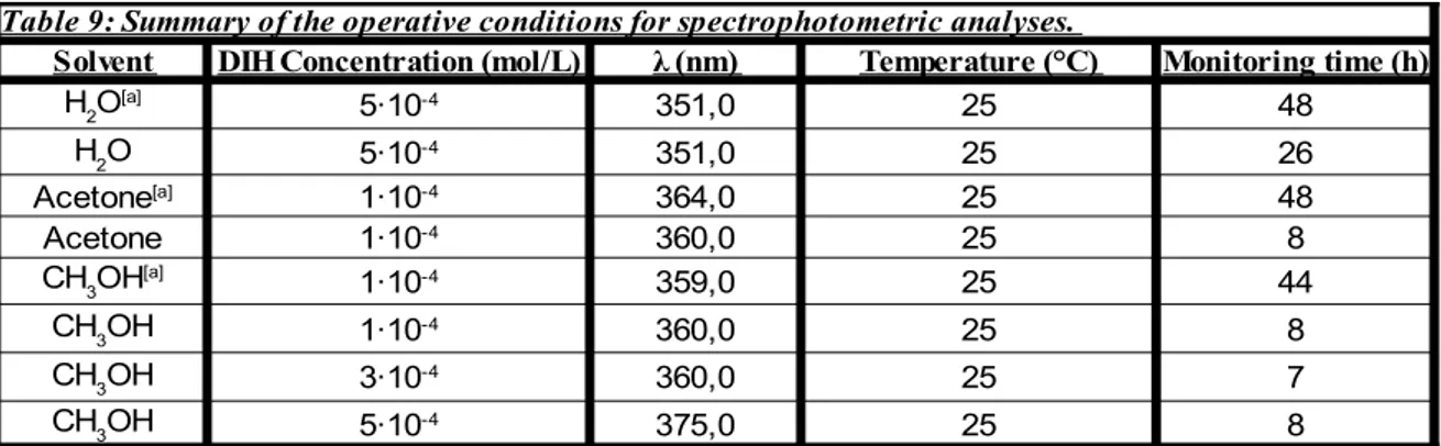
3.8 Spectrophotometric analysis of DIH solutions 23
3.9 HPLC analysis of DIH solutions 23
4. Results e Discussion 27
4.1 S ynthesis of 4 (5)-Iodoimidazolium chloride 27
4.2 S ynthesis of 4,5-Diiodo-1H-imidazole in batch 29
4.3 Synthesis of N-tosyl-4,5-iodoimidazole 32
4.4 Synthesis of 4-Iodoimidazole by selective deiodination 32
4.6 Quality control of the DIH 37
4.7 Results of the solubility tests for the DIH in different solvents 39
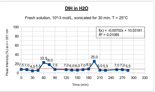
4.8 Spectrophotometric analysis of a DIH solution in water 40
4.9 Spectrophotometric analysis of a DIH solution in acetone 43
4.10 Spectrophotometric analysis of a DIH solution in methanol 45
4.11 Considerations about the spectrophotometric analysis 48
4.12 Spectrophotometric and HPLC analysis of DMH solutions in methanol 49
4.13 HPLC analysis of a DIH solution in methanol 52
4.14 HPLC analysis in methanol – effect of the temperature 62
4.15 HPLC analysis of a DIH solution in water 68
4.16 Spectrophotometric analysis of p-toluenesulfonyl chloride solutions 71
5. Conclusions 74
6. References 75
1.
Abstract
This Master thesis presents the results obtained in the curricular traineeship, carried out within the laboratories of the Department of Chemistry of the University of Bergen, during the Erasmus period, and within the Department of Industrial Chemistry of the University of Bologna. The project followed in Bergen concerned the synthesis of key intermediates used for the functionalization of the backbone of imidazole, using N,N'-diiodo-5,5-dimethylhydantoin (“DIH”) as an iodinating agent, and employing an innovative kind of chemical reactor: the “Multijet Oscillating Disc Millireactor” (MJOD Reactor). Afterwards, the work performed in Bologna consisted in verifying the stability in solution of the above mentioned N,N'-diiodo-5,5-dimethylhydantoin utilising spectrophotometric techniques and High Performance Liquid Chromatography analyses (HPLC).
In questa tesi di laurea magistrale si presentano i risultati ottenuti nel tirocinio curricolare, effettuato nei laboratori del Dipartimento di Chimica dell'Università di Bergen, durante il periodo Erasmus, e all'interno del Dipartimento di Chimica Industriale dell'Università di Bologna. Il progetto seguito a Bergen ha riguardato la sintesi di intermedi chiave utilizzati per la funzionalizzazione del “backbone” dell'imidazolo (i carboni C4 e C5), utilizzando N,N'-diiodo-5,5-dimetilidantoina ("DIH") come agente iodinante, e impiegando un innovativo tipo di reattore chimico: il "Multijet Oscillating Disc MilliReactor" (Reattore MJOD). Successivamente, il lavoro svolto a Bologna è consistito nel verificare la stabilità in soluzione della suddetta N,N'-diiodo-5,5-dimetilidantoina utilizzando tecniche spettrofotometriche ed analisi con cromatografia liquida ad alte prestazioni (HPLC).
2. Introduction
2.1 The role of functionalized imidazoles in medicinal chemistry
During the last years, the research of chemical synthesis explored in different ways the functionalization of imidazoles, due to the high importance of functionalized imidazoles in the field of medicinal chemistry. Imidazoles are a well known class of heterocycles: they include several substances that were studied because of their relevant chemical and biological interest. It is also known that they are part of a great number of very significant biomolecules, for instance: the important amino acid “histidine”, some other related compounds as biotin, and the imidazole alkaloids too.
Since imidazole drugs have several applications in different areas of clinical medicine, it is clear that the insertion of the imidazole nucleus is a very important synthetic strategy in the discovery of new effective drugs. More specifically, the imidazoles are also known for being antifungal azole derivatives that have a large range of significant activities, both in vivo and in vitro. Therefore, these molecules are currently used as strategic tools in many pharmacological studies. Because of their remarkable therapeutic properties, imidazole related drugs gave reasons to the medicinal chemists to develop and test a considerable number of new molecules, and some of these have shown interesting chemotherapeutic properties[1].
Furthermore, functionalized imidazoles are useful precursors for N-heterocyclic carbenes ligands not only in organocatalysis, but also in homogeneous transition metal catalysis[2].
It was reported in previous studies that N-heterocyclic carbenes can be compared with phosphines and cyclopentadienyls because of their capability of bonding and reactivity[3].
For all these reasons, achieving improvements in the synthesis of this kind of molecules results particularly interesting. It is of primary importance to research and develop novel procedures for the functionalization of the imidazole that can be reproduceble, selective and possibly “green”, both for future industrial applications and for further academic research. It is particolarly important to discover efficient synthetic strategies that permit unsymmetrical substitution on the C-backbone of the imidazole skeleton.
2.2 Scope of the present research
reaction from bench scale to a bigger scale (procedure of “number-up”, in a scale-up perspective), utilising a particular kind of reactor: the “Multijet Oscillating Disc Millireactor (MJOD)”[4]. Both this specific type of reactor and the considered reaction
were previously developed in the laboratories of the Department of Chemistry of the University of Bergen from the research team directed from professor Hans-René Bjørsvik, through an extensive period of dedicated studies and researches[5]. The
reactions that were investigated are represented in the following image, which shows synthetically the pathways that were taken in consideration in order to get to the molecules of interest: imidazoles substituted with iodine on the C-backbone (C4 and C5). In the picture:
A): di-iodination reaction[5];
B): selective de-iodination reaction[6];
C): mono-iodination reaction[5].
This reactions lead either to 4,5-Diiodo-1H-imidazole or to 4(5)-Diiodo-1H-imidazole. Then, it is possible to perform another reaction with these molecules and p-toluenesulfonyl chloride in order to obtain, respectively, N-tosyl-4,5-diiodoimidazole or N-tosyl-4(5)-iodoimidazole, which would be the products of major interest, in this case.
The reason why these two chemical species would be of so great importance is because there is currently a collaboration between the mentioned Department of Chemistry and the Hospital of Bergen, which is interested in these molecules for their potential applications as “tumour marking compounds”. Nowadays there is a significative attention for further development in this area of medicinal chemistry, and this project takes its part in it.
2.3 The iodinatin
g agent: N,N'-diiodo-5,5-dimethylhydantoin (DIH)
The team of Bjørsvik firstly developed a process for being able to produce mono- and di-iodinated imidazoles using N,N'-Diiodo-5,5-dimethylhydantoin (DIH, C5H6I2N2O2, CAS: 2232-12-4) as iodinating agent[5]. DIH at room temperature is a light brown
powder, which is stable when kept dry at relatively low temperature (ambient temperature or below) and, since it possesses a high content of iodine, it has a light iodine odor. DIH was prepared for the first time by Orazi and his collegues in 1965 by reacting iodine monochloride (ICl) under basic conditions with 5,5-dimethylhydantoin (DMH, C5H8N2O2)[7]. In their work, Orazi reported that the DIH showed "general
applicability for nuclear iodination of homo- and heteroaromatic compounds activated by electrondonating substituents". His research team was also able to prove that the iodination of amino and acetylamino aromatic substrates happens via the intermediate formation of N-iodo derivatives, and this was demonstrade by isolation of 2-(iodoamin0)-4,6dimethylpyrimidine and 2,4-dimethyl-6-(N-iodo-N-acetylamino)-pyrimidine.
- Picture 2: Molecular structure of N,N'-diiodo-5,5-dimethylhydantoin (DIH)
DIH manifests a reactivity comparable to that of molecular iodine, but it is far more simple to handle because it is a solid reagent, as said, and it does not sublimate as iodine does. It is worth of metioned that DIH possesses the same selectivity as N-iodosuccinimide (NIS) and equal, or even better, halogenating capability. Orazi observed that DIH can react with enol acetates derived from both saturated and unsaturated
ketones, like N-iodosuccinimide does, giving α-iodo ketones in satisfactory yields in the process[7]. DIH can be more economical in comparison to NIS, thanks to its two N–I
bonds, and it has been used as an oxidizing agent or as an iodizing agent in several production processes in different fields: (agricultural, pharmaceutical, food industries, and so on). It is quite easy to find examples in the scientific literature that can testify
this[8][9][10]. For all these reasons, DIH was taken in consideration as potential iodinating
reagent in the previous project of Bjørsvik's group of research. Thanks to the Multijet Oscillating Disc Reactor developed in their laboratories, team Bjørsvik managed to produce a large quantity of DIH, which was used in the experiments and tests that were performed in this project.
2.4 The reaction mechanism of the iodinating process
Bjørsvik and his colleagues reported in their paper[5] that the iodination reaction can be
performed following two different synthetic routes that give, respectively, the mono-iodinated or the di-mono-iodinated imidazole (the specific procedures to do these reactions are reported at paragraph 3.2 and 3.4)[5].
- Picture 3: the mono-iodination and the di-iodination reactions
Orazi and his collegues7] discussed for the first time a possible radical mechanism for
iodination using DIH as iodinating agent but, since they observed that the DIH did not have a role in the iodination of toluene (utilising benzoyl peroxide as radical initiator),
this appeared in turn to be improbable. Then, they made deeper researches, after which they ended up proposing a mechanism that involved the production of an electrophilic I+.
This specie was thought to be the iodinating agent, at that time. After some years, Chaikovskii and his collegues[11] found out that the DIH is able to succesfully iodinate,
aromatic amines, phenyl ethers and alkylbenzenes in organic solvents. They also discovered that the reactivity of electrophilic iodine is controlled by the acidity of the medium where the reaction takes place, since a superelectrophilic iodine is generated via dissolution of DIH in sulfuric acid. Then, this iodine reacts with electron-deficient arenes leading to formation of the respective iodo derivatives, at 0 to 20°C, giving interesting yields in the process. Basically, when DIH is treated with concentrated H2SO4, both of its
two N-I bonds are broken and the iodine atoms are removed from DIH. This experimental observation induced Chaikovskii to propose the formation of an iodine hydrogen sulphate (HOSO2OI) as the molecula to conduct the pre-iodination in the
reaction. Some DFT calculations were also executed, and the results gave reasons to suppose that the homolytic disassociation of iodine hydrogen sulphate was more probable, if compared to a heterolytic bond dissociation. Afterwards, Bjørsvik and Sandtorv[5] decided to explore more in depth some mechanistic aspects, taking in
consideration the di-iodination of imidazole as a model reaction in their experiments. From their experiments, it emerged that the first step of the reaction mechanism involves the protonation of DIH, performed by a strong acid (HB). The following step depends on the quantity of the mentioned strong acid.
Fundamentally, there are two main possibilities:
If we are under conditions of a relevant excess of the strong acid HB, then the DIH becomes protonated and it reacts further to give the active iodinating specie [HBI+] B. This specie is very reactive and it has a strong electrophilic character, and it can iodinate even highly deactivated aromatic rings.
Instead, In the other case, if we are working just with catalytic quantities of the acid HB, then the protonated DIH undergoes N-I cleavage and produces the iodonium species “BI”, which is significantly less reactive and less electrophilic than [HBI+] B.
- Picture 4: Reaction mechanism of the iodination reaction
2.5 The selective deiodination reaction
In another previous study, Bjørsvik and Sandtorv projected, developed and optimized a three-way switchable Pd-catalysed process that can effect transformations on the carbon atoms of the imidazole backbone (C4 and C5)[6]. This process is microwave assisted and
it provides a hydrodehalogenation or a selective arylation of the imidazole backbone. The hydrodehalogenation and a cross-coupling reactions were conducted one after another with good results in “the third switch position” that realizes an assisted tandem reaction sequence, giving 4(5)-aryl-1H-imidazole as a final product. The “arylation switch position”, instead, was optimized to synthetise the 4,5-diaryl-1H-imidazole. Finally, the “hydrodehalogenation switch position” was utilised to produce the 4(5)-iodo-1H-imidazole. This last reaction, in particular, is the one that interests us the most in this case: it was tried in order to look for alternative ways to produce 4(5)-iodo-1H-imidazole by deiodination of the 4,5-iodo-1H-imidazole previously synthetised via di-iodination reaction with DIH, as discussed in the former paragraph.
- Picture 5: The Pd-catalysed selective deiodination reaction
2.6 The microreactor technology
During the last years, there has been a substantial demand for synthetic processes to be as “environment-friendly” as possible, especially in the fields of pharmaceutical chemistry and fine chemistry. This implies finding synthetic routes that are able to provide the target molecules with the highest possible yield and selectivity, while at the same time producing the least wastes and minimizing the use of hazardous or toxing reagents and solvents. The significative progress in the synthetic processes, with and without catalysis, is also testified by the development of a new type of technology: the so called "flow chemistry" in the form of "microreactors", which were designed and presented in the scientific community as optimal and advantageous tools to perform various kinds of sythesis, for the production of pharmaceutical ingredient and fine chemicals[12].
Microreactors give the possibility to conduct organic synthesis in a continuous flow, which is a valuable alternative to the "classical" batch system. Naturally, when we talk about "batch", we usually refer to the laboratory flask on a laboratory scale and to the stirred tank reactor (STR) on an industrial scale (both for pilot reactors and for full scale plants). The microreactor technology is caracterised by excellent mass- and heat-transfer properties, if compared to the common batch, and therefore it is easy to understand why, nowadays, several kinds of microreactors are commercially sold from various companies[13]. The miniaturisation of the equipments is revolutionising chemical
synthesis, generally producing with higher yield and purity and in a shorter time. The progressive expansion of this kind of technology is also leading to a new way of conceive the implementation of synthetic processes from the laboratory scale to a pilot plant and, at the end, to an industrial production on a larger scale. Generally, a process of organic synthesis that is completely developed can be transferred from the laboratory directly to the production scale thanks to the concept of "number-up" (instead of "sizing-up") during a scale-up procedure. Currently, two different types of microreactors have been designed
and developed: the "micro-structured reactors" and the "chip-based microreactors". The formers are commonly employed in organic process chemistry, instead the latters are tipically utilized for academic research purposes[14]. Concerning the structure of
microreactors, they are generally made of miniaturized channels incorporated in a flat surface, which can be made of different materials such as: glass[15], silicon[16], stainless
steel[17], or also some kind of polymers (like polydimethylsiloxane, for instance)[18]. One
of the most common material used to construct various equipment for chemistry purposes is glass, because of its high resistance against different acids, bases, solvents and numerous reagents. Silicon is another option: it is more used in those reactions that must be performed at high (or low) temperatures[16], because of its good heat-transfer capacity
and thermal conductivity; and it manifests similar properties to those of glass when it is in its oxidized form, which may also be exploitable to our advantage. The most commonly used material for building microreactors though is still Stainless steel, especially in the area of process chemistry where it is employed in pilot plant. It is also utilised in fine chemical industry, where usually a battery of microreactors work in parallel at the same time. Microreactors made of polymers also exist and they have been used to conduct reactions at atmospheric pressure in aqueous medium[19], but they
generally tend to have lesser performance because of the lower tolerance against the majority of the solvents and reagents. Microreactors, and flow systems in general, have proven their uselfulness in many different areas of the organic process research, as it is attested by several examples in the scientific literature[20-22]. However, it is also true that
microreactor systems possess some important limitations when it comes about performing synthetic reactions, namely:
it may happen that solid particles can obstruct the network of the thin channels of the microreactor during the course of liquid-solid reactions;
when a solid catalyst is necessary, then it must be present as cartridges inserted inside the reactor, included in the microreactor and immobilized by grafting on the channel walls, or located in poles of very small dimentions in the reactor channels which may be tricky to do[23-25];
if there are any solubility problems, then the undissolved solid particles may cause clogging of the reactor channels;
reduced capacity of production;
it is complicated to perform telescoped processes, where two or more reaction are done in sequence into the same reactor body;
it is challenging to conduct multi-phasic reactions (liquid, liquid-solid, or gas-liquid-solid);
some processes need long reaction times (and long residence time in the reactor, as consequence).
In the scientific literature there are examples of gas-liquid two phase reactions that were conducted using microreactors, such as halogenations by elemental fluorine and chlorine
gas[26,27], and also some cases of liquid-gas-solid multiphase reactions[28,29], but to do them
utilising microreactor systems has been proved to be a complicated operation. Moreover, concerning multistep syntheses using microreactors, some examples have been reported , but they are still few[30,31]. Nowadays, some other systems to conduct continuous flow
organic syntheses exist, but they are still of limited number. Both the standard tubular (plug) flow reactors and the oscillatory flow mixing reactor[32] currently have heavy
disadvantages, when compared to a microreactor. This is due to the fact that a tubular reactor usually requires a high length-to-diameter ratio in order to perform reactions that are caracterized by a long residence time, and they are rather difficult to control properly. On the other hand, this is not a problem for an oscillatory flow mixing reactor, but the "contact area versus reactor volume" ratio is not optimal enough if compared with a microreactor. It must be pointed out that this is a parameter of critical importance when it comes to keep a precise control on the reaction temperature and on the heat that is generated in an exothermic reaction (since the selectivity of the reaction itself is related to it).
2.7 The Multijet Oscillating Disc Millireactor (MJOD Reactor)
In the last years, Bjørsvik's research team projected and developed several different approaches for performing organic reactions in a continuous flow reactor system. This paragraph presents an outlook about this specific kind of approach, as studied and described by Bjørsvik himself and his colleagues[4], which keeps the advantages of
microreactor systems (the good mass-transfer and heat-transfer properties) while at the same time not suffering for their most common disadvantages. Nowadays, the
microreactor technology is already well established in the scientific community. This technology is usually characterised by mixing the reagents in channels of micrometric dimensions. Instead, the approach for continuous flow processing is executed in multimillimeter-sized channels, hence using a “millireactor system”. In this particular system, the reagents and the catalysts (if any) undergo a mechanical mixing that generates an optimal heat and mass transfer. The flow reactor system was designed and built up in order to do continuous flow organic synthesis on a milli-scale, utilising the so called “Multi-jet Oscillating Disc Reactor” (MJOD reactor).
This reactor possesses four different parts: 1. the section(s) to feed the reagents;
2. the section(s) of the reactor and of the heat exchanger; 3. the outlet and pressure regulator section;
4. the oscillator.
- Picture 6: Synthetic scheme of the “ Multijet Oscillating Disc (MJOD) Reactor”
It is possible to connect these segments in multiple ways in order to customize the reagent inlet patterns and the reactor length as necessary, thanks to the fact that each reactor section has a set of male and female joints. In particular, the male joint of each unit is provided with four reagent inlet channels (the input channel is made to connect standard flangeless nut and ferrule to the reactor body). Furthermore, each section is also
connected to a standard size flange (o.d. 40 mm). The different reactor elements are connected to each other by several flange swing clamps. These are standard swing clamps (o.d. 50 mm) for flange fittings, as used for vacuum lines and fittings for oil vacuum pumps. Moreover, the reactor includes some external supporting units too, which are:
pumps to feed the reagent with reservoirs;
heating and cooling machine(s), which are provided with a circulator pump to allow the flow of any heating (or cooling) fluid. This fluid circulates through the heat exchanger cap that enfolds the whole reactor tube;
a direct current power supply (U = 0 – 24 V), so that it is possible to controll the frequency of the oscillator (by monitoring the number of revolutions and the rotation of the electrical motor,).
The MJOD unit is located inside the reactor tube, which consists in the perforated discs (the multijet discs) that are integrated on the oscillator piston shaft with some space between each other, always providing a standardized volume of 0.6 mL in this way. Each section of the reactor is also provided with a male and female joint pair. These joints are what make the MJOD system assemblable in various ways, in order to be customized for the particular necessities of the specific reaction. This configuration consents to set up the residence time inside the reactor both with the pump rate and by varying the length the reactor body. It is also possible to keep a precise control on the temperature of the reaction mixture and to adjust the mass-throughput when collecting the product. Both the reactor and the heat-transfer chamber are made of stainless steel tubes. The reactor tube (o.d. 12 mm, i.d. 10 mm) is surrounded by a second larger tube (o.d. 37 mm, i.d. 33 mm), made of stainless steel, and the space that is created in between is used to let the cooling fluid (water) circulate in order to keep the temperature under control. The inlets and outlets can be disposed at different levels of the length of the reactor, as required for the specific experiment, thus allowing the heat-transfer fluid to flow in and out at different points of the reactor itself. More specifically, the tube of the MJOD reactor is surrounded by an insulating coat, and the cooling, or heating, fluid (water, in this case) is let to flow inside it, by means of a pump. This cooling/heating coat can be divided different sections. Therefore, it is practically possible to divide the body of the reactor in more different "temperature zones". For instance, this is a necessary feature if one desires to
perform a "telescoped multistep synthesis" (i.e. synthetic processes that are composed of several reactions), since different reaction temperatures are required in the process. Thanks to the DC power supply, the reactor tube has an adjustable frequency (0.5 Hz) and amplitude (0.25 mm), which helps to achieve an optimal mixing, and an oscillator that moves the multijet disk unit back and forth longitudinally. The MJOD unit is basically a piston engine with multiple piston heads (the equally spacied four-jet discs) disposed on one piston shaft. The reagents are feeded to the reactor tube by the pumps, as previously mentioned. By means of the pressure generated by the pumps, the reagents will flow through the holes (the jets) of the discs that are located on the piston of the MJOD unit, with a high rate. There is a technical problem that must be avoided, though: the alternating pressure produced by the oscillating piston shaft could potentially provoke a “back kick” of the reaction mixture into the reagent feeding tubes (and into the pumps, as a conseguence). This issue is easily bypassed by supplying the reagent inlet lines with "one-way valves". When the reaction mixture passes through the disc holes and arrives into an area of a larger cross section (like the reactor cavity), then the flow rate decreases, which produces vortexes and very turbulent movements that make the mixing of the reagents so optimal. Furthermore, the mixing inside the reactor is improved even more by the movement of the discs fixed on the oscillating piston. The oscillator is made of two parts: the engine unit and the agitation. The agitation unit consists of a piston shaft with numerous perforated piston heads equally spaced in the length of the piston itself. The piston length is egual to the reactor length plus the distance between the end of the reactor tube and the joining point on the cam wheel of the electrical motor. The piston heads are perforated ring-formed discs (o.d. = 10 mm, L = 4 mm) made of Teflon (PTFE), chosen for its well know high chemical resistance. Each one of these discs has four jets with a diameter in the range d = 1.00-1.30 mm. The piston shaft with its discs fits very closely to the reactor tube walls. With this configuration, there is a thin annular cavity between the inner surface of the rector tube, two discs, and the piston. This cavity is what generates the internal surface of the reaction cavity. In general, the number of reaction cavities can be modified as necessary, and specifically in this project the piston shaft supported 60 equally spaced discs (10 mm o.d. with 4 x 1.25 mm diameter jets). The 59 cavities that are located between the discs, along with the reaction cavities, provided a total volume of ≈38 mL. Also the length of the reactor tube can be varied as
desired, but it was observed that one meter of length from the first feeding point to the product outlet point is usually the best option for several kinds of reactions and processes. Therefore, this was the tube length that has been used for all of the performed experiments. Since many different set-ups can be arranged with the MJOD reactor, it has been tested by performing various reactions that are currently in use both on research and on industrial level (using both batch and microreactor protocols), in particular: the Nef reaction, sodiumborohydride reduction , the Haloform reaction, the Paal-Knorr pyrrole synthesis, nucleophilic aromatic substitution, O-allylation, N-acylation, the Suzuki cross-coupling reaction and the Hofmann rearrangement. For instance, using the MJOD reactor while performing the Paal-Knorr reaction resulted in a 2837 mmol/h production of 2-(2,5-dimethylpyrrol-1-yl)ethanol, starting from 51,4 mL of a β-aminoethanol solution (851 mmol) and 100 mL of a acetonylacetone solution (852 mmol)[4]. In following
projects, the MJOD reactor was also succesfully used to conduct other reactions: organocatalyzed epoxidation of alkenes[33], synthesis of phenylboronic acids at cryogenic
temperatures[34], and lithiation/borylation reactions[35], giving satisfactory results in all the
cases. Currently, moreover, there are more studies and project designs that are under progress concerning the MJOD system. These researches are founding evidences that this kind of reactor may be suitable to conduct gas- liquid reactions with molecular oxygen as oxidant agent, different metallorganic reactions that need low reaction temperature metallorganic reactions that need low reaction temperature, telescoped reactions, olefin metathesis reactions, and also other different reactions that require a protecting atmosphere with an inert gas, such as nitrogen or argon.
2.8 The stability of
N,N'-Diiodo-5,5-dimethylhydantoin in solution
Since it was previously known that DIH could present some form of instability in a solution, it would be necessary to develop and implement a quantitative analytical method, based on HPLC analysis, to observe the stability of DIH in different solvents. At the best of our knowledge, although some former reserches were know to employ HPLC techniques to analize and separate different kinds of hydantoins, no specific study concerning the DIH was done until now[36-38]. Therefore, in order to draft an analytical
protocol as previously mentioned, some preliminary analyses are necessary. More specifically, since the HPLC instrument uses a spectrophotometric detector which works
in the UV-Visible range of wavelength, it is first needed to verify where does the DIH absorbs in that range. Since the DIH solutions are coloured, it is easy to suppose that it should give some absorption in the visible range. In the scientific literature there are no data whatsoever concerning UV-Vis spectra for DIH, and this is the reason why some preliminary tests are required. At the same time, monitoring the variations of absorbance with time, it is possible to perform a qualitative observation of the stability of DIH in solution, using water, acetone and methanol as solvents.
2.9 The stability of
p-toluenesulfonyl chloride in solution
As seen in the previous Picture 1, p-toluenesulfonyl chloride (tosyl chloride) is the reagent that has to be employed in the final steps of the synthetic procedure, in order to obtain N-tosyl-4,5-diiodoimidazole and N-tosyl-4(5)-iodoimidazole. Because of its importance in this synthetic route, it was decided to test its stability in solution in an analogous way as done for the DIH. For tosyl chloride, however, no HPLC resulted necessary: its stability was verified just using spectrophotometric methods. The details concerning the spectrophotometric analyses are reported in the following paragraph 3.6
- Picture 7: Synthesis of N-tosyl-4,5-diiodoimidazole and N-tosyl-4-iodoimidazole. “R” represents a tosyl group (CH3C4H6SO2).
3. Experimental section
3.1 Methods
The MJOD reactor has a total volume of 65 mL and it was provided with two “QG low speed – low flows” pumps by Fluid Metric Incorporated (60 Hz, shaded 2 pole, enclosed ventilated, thermally protected, pump drive “QG20”, piston code “Q1”). The pumps were set in order to have the reservoirs with reagents completely depleted at the same time. The engine was set up so that the oscillations of the piston shaft increased proportionally to the applied voltage, as shown in the following picture.
Water was used as cooling fluid, which circulated through a set of tubes. In order to keep the water at 0°C its main reservoir has been filled with ice.
Control 1H NMR spectra were obtained on a NMR spectrometer, which operated at 400
Mhz/52 MM (Bruker). Chemical shifts were referenced to the deuterated solvent (D2O or
CDCl3).
Control GC analyses were performed on a capillary gas chromatograph “GC 800 Series” (Fisons Instruments), equipped with a fused silica column (l 25 m, 0.20 mm i.d., 0.33 mm film thickness) at a helium pressure of 200 kPa, split less/split injector and flame ionization detector. Mass spectra were obtained on a GC-MS instrument, using a gas chromatograph equipped with fused silica column (l 30 m, 0.25 mm i.d., 0.25 mm film thickness) and helium as carrier gas.
Control FT-IR spectra were recorded on a "Nicolet 380 FT-IR" instrument (Thermo Electron Corporation).
The routine pH tests were performed using a B27 pH Lab instrument (“Metrohm”), equipped with a 3 M KCl glass electrode, which has been calibrated with two buffer solutions (pH 4 and 7).
The UV-Vis spectra were obtained using the following instruments:
Double beam spectrophotometer: “Cary 1E UV/Vis Spectrophotometer” (Varian), which can record spectra in the wavelength region λ = 190 – 900 nm, equipped with a “Cary WinUV” program;
Single beam spectrophotometer: “Jenway 6405 UV-Vis Spectrophotometer” (Barloworld Scientific), which can record spectra in the wavelength region λ = 320 – 1100 nm;
The microwave reactor was a “Initiator” equipment (Biotage®).
The instrument utilised for the ultrasonic bath was a “Transsonic 700/H” (Tamro) machine.
The rotavapor machine was a “Rotavapor R-3” (Buchi Switzerland) with a vacuum controller V-850 and a vacuum pump V-700.
Operations of purification were performed using an Autoflash “Reveleris® X2 Flash Chromatography System”, equipped with two UV detectors (set up at λ=254 nm and
λ=280 nm) and one ELSD detectors (threshold detection: 6mV), using a “Grace ResolvTM” column (silica, 4 g/5 mL), isopropanol as carrier and hexane/ethyl acetate as
eluents, with a flow rate of 36 mL/min.
All the chemicals were used as received, except N,N'-diiodo-5,5-dimethylhydantoin (DIH) that was previously produced with the MJOD reactor during a foregoing project, as previously mentioned.
All of the data analysis were performed using the software “OpenOffice Calc”.
3.2 Synthesis of
4(5)-Iodoimidazolium chloride by iodination reaction
A round-bottom flask was filled with water (50 mL) and immersed in an ice-bath. Imidazole (0.388 g, 5.70 mmol) and KI (12 g, 72 mmol) were transferred to the flask and the mixture was stirred until the solids were dissolved. NaOH (3.7M, 50 mL) was then added. Sulphuric acid (5 mL) was added to N,N’-diiodo-5,5-dimethylhydantoin (0.519 g, 1.4 mmol) in a separate flask and manually stirred in a vigorous way. The resulting dark and viscous mixture was slowly added drop-wise with a Pasteur pipette to the imidazole solution over 10 min of time.After the addition, the reaction mixture was neutralized with acetic acid (pH~6). A saturated solution of K2SO3 (1 mL) was added and finally the solution was saturated with
NaCl. During all these steps, the mixture needs to be kept in the ice bathThe clear solution was extracted with ether (3x40 mL) and the combined, organic phases were again extracted with 10% HCl (3x10 mL). The aqueous solution was evaporated with a rotavapor to about half the volume and the white precipitation filtered off. Yellow crystals of the title compound were crystallized from the aqueous hydrochloric acid solution.
3.3 Synthesis of 4
-Iodoimidazole by selective deiodination reaction
4,5-diiodo-1H-imidazole (0.34 mmol), XPhos (0.15 mol%), phenylboronic acid (3.0 equiv.), K2HPO4 (2.0 equiv.) and TBAB (0.025 mmol) were transferred to a micro-wave
reactor tube equipped with a magnetic stirring bar. The vial was sealed and carefully flushed with argon. Methanol/water (4:1) (5mL) was added to the tube and a fresh solution of Pd(OAc)2 in methanol was prepared. To the vial, Pd(OAc)2 solution was
added (0.15 mol%) by means of syringe. The vial was then submerged into the micro-wave cavity and heated to 120oC for 75 minutes.
3.4 Synthesis of
4,5-Diiodo-1
H
-imidazole by diiodination reaction
Imidazole (0.076 g, 1.1 mmol) and N,N’-diiodo-5,5-dimethylhydantoin (0.345 g, 0.91 mmol) were transferred to a round-bottom flask immersed in an icebath. Water (2 mL) was added and the heterogeneous mixture was stirred during the drop-wise addition of sulphuric acid (1 mL) over 1 min. After the addition, NaOH (3.9M, 15 mL) was added. The resulting milky solution was then neutralized (pH~6) with acetic acid which resulted in precipitation of the product. The crystals were filtered, washed multiple times with cold water and saturated K2SO3 solution (3x3 mL) and allowed to air-dry to constant
weight to give the product as creamy crystals. Traces of 4-(5)-iodo-1H-imidazole were also observed in the isolated product.
3.5 Synthesis of
N-tosyl-4-Iodoimidazole
4(5)-diiodo-1H-imidazole (5.46 g, 28.2 mmol) and p-toluenesulfonyl chloride (5,38 g, 28,2 mmol) were transferred to a Schlenk tube under argon atmosphere. Then dry THF (40 mL) was added to dissolve the solids. After that, NEt3 (4.0 mL, 28.2 mmol) was
added drop-wise, using a syringe. It is important that the reaction is conducted under completely dry conditions, therefore it is necessary to preventively dry all the equipment (Schlenk tubes, magnetic stirring bar, etcetera) with a heat gun before proceeding. The reaction mixture was stirred for 24h at ambient temperature while keeping the argon atmosphere. This procedure has been employed to try to synthesize N-tosyl-4,5-diiodoimidazole starting from 4,5-diiodo-1H-imidazole.
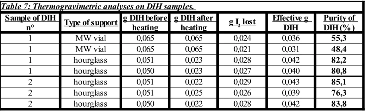
3.6 Analyses to determine the quality of the DIH
To estimate the quality and the purity of the DIH two different kind of analyses were performed: FT-IR analyses and thermogravimetric analyses. Regarding the recording of the FT-IR spectra, the only required precaution is to preventively dry the DIH sample, since otherwise the water band could cover part of the spectrum. Therefore, the DIH samples were left to dry under vacuum for 2 days before recording the FT-IR spectra. Concerning the thermogravimetric tests, during these experiments a know amount of
DIH was deposited on an appropriate support which was slowly heated from the bottom with a heat gun (see the following Picture 9), until fumes of iodine were released. This phenomenon is usually accompanied also by the solid turning of a darker colour.
- Picture 9: Disposition of the equipment during the thermogravimetric analyses.
Weighting the support before and after the heating allows to find out the quantity of lost iodine, and thus the DIH quantity. In this way, it is easy to obtain an estimation of the DIH purity.
3.7 Solubility tests for the DIH in different solvents
It is useful to know the DIH solubility in the solvents that are supposed to be used in the spectrophotometric analyses and HPLC tests, before actually performing them. Since at the best of our knowledge no specific data about can be found in the scientific literature, we had to try to obtain at least an estimation of its solubility by ourselves.
These preliminary experiments consisted in weighting a known amount of DIH in a flask and progressively adding the chosen solvent, one millilitre at time using a calibrated pipette, until the solid was completely dissolved at room temperature. In order to generate an optimal mixing, a vigorous magnetic stirring was also applied to the solutions. Experiments were made using distilled water, acetone and methanol as solvents, and the obtained results are reported in the following paragraph 4.3.
3.8 S
pectrophotometric analysis of DIH solutions
Every DIH solution was sonicated for 30 minutes in an ultrasonic bath, in order to provide a better dissolution of the solid in the three different solvents (distilled water, acetone and methanol). The complete spectra of DIH were further obtained using a double beam spectrophotometer. This operation also allowed us to find out the wavelength where the DIH has its maximum peak of absorption (λmax), in every solvent.
The solution stability tests has been performed utilising both a single- and a double-beam UV-Vis spectrophotometer.
All the spectrophotometric analysis were conducted using sealed quartz cuvettes, in order to prevent any evaporation of the solvent. During the analysis with the single beam spectrophotometer, the cuvette containing the blank (the pure solvent) was put inside the spectrophotometer first, in order to register the baseline of the blank itself, and only after this registration the cuvette containing the DIH solution was put in the spectrophotometer to read the absorbance value at the λmax. Instead, when operating with the double beam
spectrophotometer, the two cuvettes could be placed inside the instrument at the same time while registering the continuous spectrum of the solution.
This procedure has been repeated at specific time intervals and, when the two cuvettes were not been analysed, they were placed closed in a dark place, far from any source of heat or light. This precaution is necessary in order to prevent some kind of undesired degradation of the DIH between one analysis and the following. This same operative methodology was also applied to the spectrophotometric analysis of p-toluenesulfonyl chloride. For the tosyl chloride, acetone and dry THF were employed as solvents.
3.9 HPLC analysis of DIH solutions
As for the spectrophotometric analysis, also for these experiments every DIH solution that was used has been sonicated for 30 minutes, for the same reasons mentioned above. The HPLC (High Performance Liquid Chromatography) system that has been used, connected with the thermostatation equipment, is represented in the following image. In the picture, from the left to the right, we can see:
1. The thermostating bath, which uses distilled water as heat exchange fluid and an alcohol thermometer to monitor the temperature;
spectrophotometric detector (with an adjustable spectrophotometric range), a 50 μL calibrated loop, and the column;
3. the recorder (Amersham Pharmacia Biotech, REC 1111).
- Picture 10: The thermostated HPLC system.
The column that has been employed was a Discovery® C18 (504971), 25cm x 4,6 mm, 5
μm of diameter for the silica particles (Supelco). The eluent flow in the HPLC system was always kept at 1,0 mL/min, and the eluent was let to run in the column for at least 15 minutes before doing any kind of test, in order to appropriately condition the column itself. We employed UPP H2O and "Hipersolv Chromanorm" CH3OH (HPLC gradient
grade, CAS 67-56-1, VWR International) as eluents. Morever, as previously mentioned for the spectrophotometric analyses, also for these experiments every DIH solution has been preventively sonicated for 30 minutes in an ultrasonic bath. This is particularly important to prevent any clogging during the injection of the solution inside the system, due to particulate that could be present in the solution.
The injections were executed with a plastic syringe (5 mL "Fortuna®" syringes) provided with a “Hamilton” needle. The syringe has to be connected to a filter (“Econofilter”, Agilent Technologies) too, which is located between the syringe and the needle. This filter helps to further prevent any remaining particulate (or suspension) to clog the system. It is also necessary to sonicate the eluent as well to degas it, for at least 5 minutes, and this is necessary to avoid that air bubbles may get stuck inside the loop, thus provoking a sudden obstruction of the calibrated loop. In fact, when we degas the eluent, usually some gas bubble are released, and after that this phenomenon is observed the
eluent is generally ready to be employed.
Concerning the analyses: the volume of DIH solution that was injected in the HPLC system at every analysis was 0,1 mL, and these injection were executed at specific time intervals (one every 15 minutes). It is worthy to mention, though, that any injection should be avoided before that the pressure of the HPLC has not been completely stabilized, otherwise this could result in unattainable data. Another important detail is the fact that no air bubble should be present inside the syringe before the first injection, for all the above mentioned reasons. This is avoided simply by filling the syringe with the solution and then “spilling” some of the liquid outside, and in this way the air bubbles that may be present will be easily ejected.
One must also be sure to reset the baseline of the recorder before every injection, to prevent any drift of the baseline itself. Moreover, in order to reduce the interferences as much as possible, two operations can be done. First of all, one has to appropriately clean the syringe with the eluent (methanol, UPP water, or else), before and after every injection. Secondly, after the first injection, the syringe will be left inside the HPLC injector, to avoid air to get in.
Having said that, the HPLC pump is able to handle a pressure between 0 and 200 atm, and it is constantly monitored by the internal software of the system. With this equipment, the analyses were made at increasing temperatures (25°, 30°, 35°C), in order to study the effect of the temperature on the degradation process of the DIH (if any). The following picture shows the employed C18 column when put under thermostatation. The heat exchanging fluid is water that continuously circulates in the glass cylinder that contains the column itself, through two plastic tubes. The whole system is sustained by metallic arm connected to a support.
The next picture shows the C18 HPLC column that has been utilised for the vast majority of the experiments. During the tests performed in water, where the analyses were more complicated to perform, we also try to use a different C18 column, which was a “Kinetex 5u C18 100A", 250 x 4,60 mm, 643153-12, purchased by "Phenomenex". The results did not improve while using this column though, and therefore after some trials it was discarded, since probably it was not what created the encountered issues (see the following paragraph 4.15).
- Picture 11: The C18 HPLC column ( Discovery® ) under thermostatation.
The experimental results obtained both with the spectrophotometric and HPLC analyses are reported in the following paragraph, with some considerations regarding their interpretation.
4. Results e Discussion
4.1 Synthesis of 4
(5)-Iodoimidazolium chloride
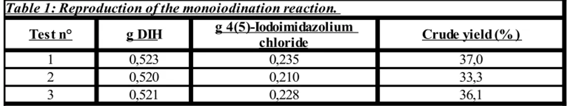
Table 1 reports the results, in terms of crude yield, of some experiments performed to produce 4(5)-iodoimidazolium chloride, via the procedure reported at the previous paragraph 3.2. In fact, the iodination reaction was performed several times in order to test its reproducibility and to see if it has passages that may be difficult to reproduce on a bigger scale, using the MJOD reactor.
The nature of the product was verified recording the FT-IR and GC-MS spectra. In particular, while doing the infrared spectra, it is important that the solid is as dry as possible, otherwise the large band of the water will cover a considerable part of the spectrum. Hence, before doing the FT-IR spectra is usually useful to dry the product with a flow of N2. Having said that, the obtained yields were not satisfactory, considering that
the article that contained the procedure[5] reported a yield equal to 81%. While
performing the reactions, it became clear that the two most critical steps of this synthetic path were: the mixing of the DIH with concentrated sulphuric acid; and the separation of the product (which involves some steps of extraction, filtration and crystallisation). Indeed, if the manual mixing is not appropriate, then the DIH does not become activated and the already mentioned super-elecrophilic iodinating agent [HBI+] B- is not formed in
a sufficient quantity, thus resulting in a lower yield (or, even worse, the reaction does not start at all). In addiction, the removal of the aqueous fractions (most of the times performed with a rotavapor), may be very slow, due to the large amount of water, which in turn slows the entire process. To remove the last portions of water, moreover, it can be also helpful to use a high vacuum pump (and this is always necessary if one wants to prepare a sample to run on a GC-MS machine, since it can not allow any water inside). Concerning the filtrations, both the conventional vacuum pump and the ”water vacuum
Table 1: Reproduction of the monoiodination reaction.
Test n° g DIH Crude yield (% )
1 0,523 0,235 37,0
2 0,520 0,210 33,3
3 0,521 0,228 36,1
g 4(5)-Iodoimidazolium chloride
pump” are suitable for this separation. In any case, though, this could be a stage where part of the product is lost, and handle the instruments with extreme care becomes critical. In particular, it is better to avoid to filtrate utilising a funnel with glass filter, since the product tends to remain stuck on its surface and it gets very difficult to remove it. The classic paper filter is more appropriate for this operation.
Trying to remove all the solvent by evaporation gave a dense and viscous oil, of a yellow/orange colour, as result. The reason is easy to understand, considering that the mono-iodoimidazole is not volatile because it forms hydrogen bonds between its own molecules. Regarding the crystallisation, some trials were made using an ice bath with salt (NH4Cl). Naturally, if it is used a salt which is not a powder, like CaCl2, one must
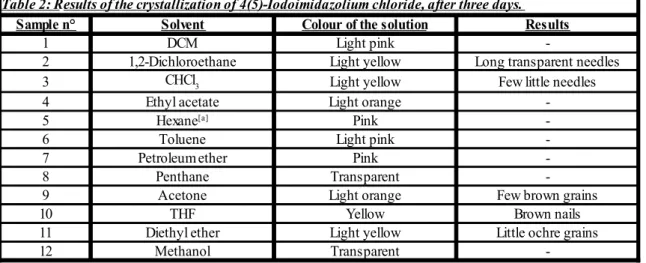
grind the salt in advance in order to make it a powder and thus providing a better contact between the ice and the salt itself. However, this kind of approach did not give good results. Therefore, several re-crystallization trials were conducted in order to look for a suitable solvent to further purify the 4(5)-iodoimidazole from the remaining salt (CH3COONa, which is present as a consequence of the neutralisation of NaOH with
acetic acid). This new set of experiments gave the results reported in the following Table 2:
[a] The hexane is a mixture of isomers, boiling point: 68-70°C.
The most interesting observations were obtained employing 1,2-dichloroethane, THF and chloroform. In general, it seems like chlorinated solvents can provide better results. Performing GC-MS analyses confirmed the presence of the desired product. Anyway,
Sample n° Solvent Colour of the solution Results
1 DCM Light pink
-2 1,2-Dichloroethane Light yellow Long transparent needles
3 Light yellow Few little needles
4 Ethyl acetate Light orange
-5 Pink
-6 Toluene Light pink
-7 Petroleum ether Pink
-8 Penthane Transparent
-9 Acetone Light orange Few brown grains
10 THF Yellow Brown nails
11 Diethyl ether Light yellow Little ochre grains
12 Methanol Transparent
-Table 2: Results of the crystallization of 4(5)-Iodoimidazolium chloride, after three days.
CHCl3
after considering different possibilities regarding the separation stage of this synthetic route, it was decided to switch to the di-iodination reaction, basically because it required less tricky passages to obtain the final product (4,5-diiodoimidazole).
4.2 Synthesis of 4,5-Diiodo-1H-imidazole in batch
The di-iodination reaction was performed several times, in different batches, in order to see how reproducible it was and to find out eventual difficulties that could be detrimental for the process while using the MJOD reactor. In the following Table 1, the crude yields were calculated considering the DIH as being the limiting reagent in the adopted conditions. The presence of the desired product in the solid that was produced was verified with GC-MS tests.
The reason why the yields, apparently, are higher than 100% is because one fact has to be considered: the followed procedure[5] required a separation phase in order to get the
product, which consisted in washing multiple times the obtained solid with water and a saturated solution of K2SO3 (to remove the remaining iodine). This stage often caused the
deposition of K2SO3 itself on the solid containing the product, thus making higher the
yields. Therefore, more washing with distilled water were necessary. Hence, after a new series of washes with distilled water, the masses of recovered product were as reported in the following Table 2:
Table 3: Yields of different batches performed to produce 4,5-Diiodoimidazole.
Batch n° g DIH g 4,5-Diiodoimidazole obtained Crude Yield (% )
1 0,345 0,907 312,3
2 0,353 0,472 158,8
3 0,345 0,514 177,0
4 0,345 0,322 110,9
5 0,348 0,231 78,8
Batch n° g DIH g 4,5-Diiodoimidazole obtained Crude Yield (%)
1 0,345 0,082 28,23
2 0,353 0,079 26,58
3 0,345 0,091 31,33
4 0,345 0,037 12,74
5 0,348 0,062 21,16
Table 4: Yields of different batches performed to produce 4,5-Diiodoimidazole (after a new series of washes).
The low yields achieved this time are mainly due to the fact that there were problems in the stage of recovering the product. The actual masses of 4,5-diiodoimidazole were probably higher, but since, as mentioned, repeated washings with H2O were required, this
usually produced a loss of product. In fact, in the following experiments, the washing with K2SO3 were generally removed from the procedure for this reason. This was one of
the first issues that we had to deal with in the first troubleshooting phase.
We also performed a scale-up attempt on batch scale, multiplying the quantities of all reagents by ten times. Being aware of the technical issues encountered in the foregoing experiments, this time the washing of the final product was done mainly with water and eventually just with smaller quantities of K2SO3 solution. This resulted in an increase of
the yield, as reported in the next Table 3. Naturally, due to the bigger quantity of solid involved in this experiment, also a greater volume of water has been necessary in order wash the product in the best way possible. Therefore, 5x10 mL of water were employed, instead of 3x3 mL.
The purity of the obtained product was checked through 1H-NMR analyses. These spectra
showed that the purity of the 4,5-diiodoimidazole was on average ≈80%, and that the remaining 20% was actually 4(5)-iodoimidazole. This is expected, since it was previously reported in the article that contained the procedure that this phenomenon could happen. Hence, in this experiment, the actual yield would be 68.7%, which is still a result that is closer to the ones reported in the scientific literature[5]
It was also done an attempt to separate the 4,5-diiodoimidazole from the 4(5)-iodoimidazole and thus improving its purity. It was used an automatic chromatographic system (“autoflash”), with the equipment previously mentioned at paragraph 3.1, imposing a solvent gradient that went from 20%-80% ethyl acetate/hexane eluent to a 90%-10% mixture of the mentioned solvents. Unluckily, though, it emerged that the retention times of the two compounds were too close to allow a proper separation and a purification with this system.
More experiments were made with these reaction in order to evidence more eventual
Table 5: Diiodination reaction, x10 scale-up.
g imidazole g DIH g KI g 4,5-Diiodoimidazole obtained Crude Yield (% )
issues that could potentially complicate transferring this synthetic path on the MJOD reactor. In fact, it is also necessary to consider other factors, to avoid conditions that may negatively affect the course of the reaction, and the yield as consequence. It emerged that the pH is another key factor. After adding the NaOH 3,9 M the pH of the solution is naturally very high and it is necessary to lower it by adding an aliquot of acetic acid. Otherwise, if the pH is above 10, it is not possible to have the precipitation of 4,5-diiodoimidazole. It is worth to underline that, due to the viscosity of the reaction mixture, it is complicated (if not impossible) to check the pH using common pH paper (“Panpeha” paper), and a pH-meter is usually required. Usually, a dark, viscous and slurrish reaction mixture is observed at the equivalent point between H2SO4 and NaOH. To try to
overcome this issue, it becomes fundamental to maintain the best possible mixing. Otherwise, the high viscosity could create some pH gradients in the volume of the solution, thus complicating the reach of a suitable equivalent point. To improve the mixing, it is also helpful to operate using an “egg-shaped” magnetic stirring bar rather than a cylindric one. At higher pH (9-10), the solution becomes yellowish and almost transparent and it is possible to see crystals of product. Moreover, if the pH increases too fast, the 4,5-diiodoimidazole does not precipitate. This explains the necessity of monitoring the acidity level during the reaction.
The last major parameter to keep under observation is the temperature: theoretically, the di-iodination should take place at 0°C, and the reaction mixture would need to be kept in an ice bath for all the steps before the filtration stage. However, it was observed that if the temperature drops too quickly or if the baloon containing the reaction mixture is kept at low temperatures for too long, a considerable gelification of the mixture itself occours, which makes impossible to proceed any further due to his high viscosity (it is not possible even to titrate). It is in this kind of situation that measuring the pH become almost impracticable, since the mixture is so “gellish” and viscous that it remains attached to the surface of the pH-meter glass electrode, which as consequence senses pH always lower and lower as the seconds pass.
This tendency to give gelification apparently increases when smaller volumes of solvent are used, probably due to the increase of viscosity. This phenomenon is probably due to the presence of CH3COONa in solution, after the neutralization of NaOH with acetic
reaction on the MJOD reactor.
4.3 Synthesis of N-tosyl-4,5-diiodoimidazole
The procedures reported at paragraph 3.5 was utilised to try to produce N-tosyl-4,5-diiodoimidazole, starting from 4,5-diiodoimidazole (previously made) as substrate instead of 4(5)-iodoimidazole. Because, this reaction has never been performed in this way, two attempts were done at the same time, but the results were different to the ones expected. In fact, after the recrystallisation step with DCM, some GC-MS analyses were executed in order to verify the nature of the product. In the recorded GC-MS spectra, though, it was not possible to find any peak corresponding to the expected molecular mass of the final product (MM=470,017 g/mol), and probably the reaction did not even started.
In subsequent TLC analysis, using a 20:80 ethyl acetate/hexane solution as eluent (λ=254 nm), showed that the two reaction mixtures did not contain traces of N-tosyl-4,5-diiodoimidazole. Therefore, assuming that all the different phases of the procedure were reproduced correctly, the experimental observation suggests to make changes to the operative conditions while using 4,5-diiodoimidazole, rather than 4(5)-iodoimidazole. To find them out, however, would require a separated study, and at this stage of the project it was decided rather to focus all the effort on the production of 4,5-diiodoimidazole with the MJOD reactor.
4.4 Synthesis of 4-Iodoimidazole by selective deiodination
The procedure reported at paragraph 3.3 was used to try to reproduce the selective deiodination reaction, thus producing 4-iodoimidazole. This reaction was performed three times, but some difficulties were encountered to reproduce the expected results reaction in an fast and efficient way. More specifically:
in the first experiment, all the reagents were employed as prescribed by the procedure, with no modifications;
acid (Ph-B(OH)2), no other changes were made;
in the third one, all the reagents were utilised except phenylboronic acid and potassium hydrogen phosphate (K2HPO4), with no other changes.
Besides this, the rest of the procedure was conducted as prescribed. Concerning the execution of the reaction, it is worth to mention that, in order to provide a better dissolution of the catalyst (Pd(OAc)2), it is helpful to use an ultrasonic bath and sonicate
the palladium solution in methanol for few minutes.
After performing the reactions with the microwave reactor, GC-MS analyses were made to look for the presence of the product, but it wasn't find any. It was firstly supposed that the product needed to be purified better, so that it could have been possible to see its presence via GC-MS. Hence, a new work-up procedure was elaborated to reach this goal. This work-up involved:
1. extraction with 10% HCl (20 mL); 2. extraction with diethyl ether (20 mL); 3. neutralization with NaOH (3M);
4. filtration of the solid, washing it with distilled water, and let it air dry.
After performing this procedure, though, new GC-MS analyses were performed, but again no trace of the expected product was found. In any case, after this last series of experiments, it was decided to fully concentrate all the efforts on the reaction of di-iodination, since it is the one with the procedure that involves less passages and is therefore simpler to transfer on the MJOD reactor.
4.5 Synthesis of 4,5-Diiodo-1H-imidazole using the MJOD reactor
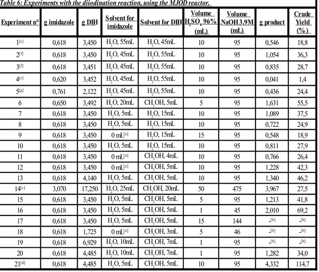
When we tried to transfer the reaction of di-iodination from batch scale to the flow reactor, different configurations of the instruments were possible. Different trials were made in order to find out the one which was more appropriate for our experiments. The first configuration that was employed consists of putting imidazole with water in the first reservoir, while having the DIH with water and sulphuric acid in the second one, as is presented in the following Picture 11:
- Picture 11: First configuration of the MJOD reactor.
This configuration turned out not to be optimal, though. In fact, when the DIH is put in contact with the sulphuric acid, it quickly starts to release the iodine, which is easy to spot since the solution manifests a characteristic purple colour. Since the sulphuric acid is the catalyst that activated the DIH, it is important to not let it have any contact with the DIH itself before that the reagent solutions are pumped inside the reactor. If DIH is mixed with H2SO4 before the feeding, then it releases all the iodine too early, giving a
quite viscous slurry which is difficult to pump inside the reactor. It is important that the contact between the two reagents and H2SO4 takes place only inside the body of the
MJOD and not before. Otherwise, the yield decreases significantly and the results are lower than usual (see the following Table 6 for further details). Therefore, it was decided to switch the configuration of the reactor. The imidazole was put with water and H2SO4 in
the first reservoir, and instead the DIH with only water in the second one, as Picture 12 shows. This new configuration has been maintained for several experiments, in order to prevent an undesired decomposition of the DIH. In particular, the water was added to the DIH reservoir only when needed, thus immediately before the feeding. Even if this prevented the degradation phenomenon, another technical problem had to be solved. In fact, some experiments had to be aborted because of considerable clogging issues with the feeding pumps that made impossible to proceed further.
- Picture 12: Second configuration of the MJOD reactor.
Basically, the DIH is not just a powder, but it can be also a granular substance. Hence, if it is not properly dissolved in the solution, the bigger grains can get stuck in the feeding pumps and in the feeding tubes. When this happens, the pumps have to be thoroughly washed to make them operative again. After observing this, a new modification to the process was made (see Picture 13).